💬 Easy/Newbie PCB for MySensors
-
@sundberg84
Thanks for the explanation!
I think I've got it now.
Will test and get back with the results when I've gotten my hands on some more solder wire!@BastienVH
Replying to myself to follow up on my assembly-issues.
I have been able to get the board to work.
I don't have my 0.1µF caps yet, so I just put a little blob of solder in the holes so the current could run through.
Now I've got myself 2 working board. I just have to find a good way to attach my PIR, dallas temp, ... to them.Thanks for the work and help!
-
I'am now finnish with my first rev7 node.
It is a Arduino 5V with DHT-22 and a HC-SR501 sensor.
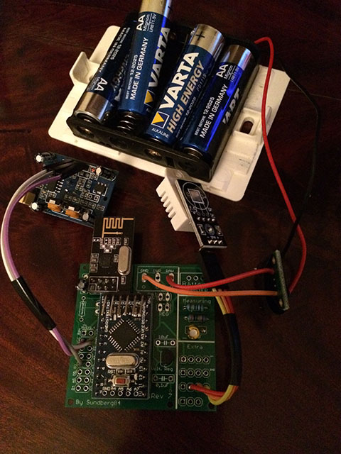
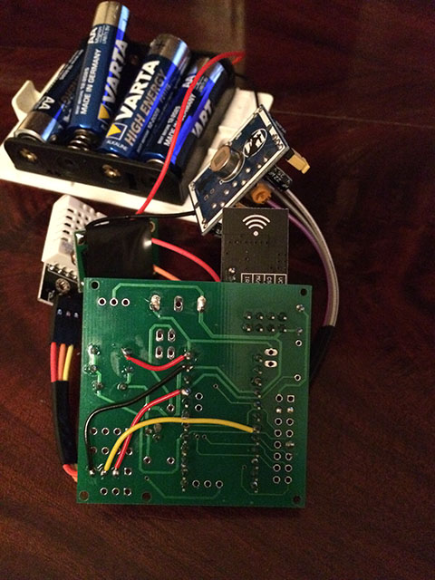
Good work @sundberg84 for the PCB
-
@BastienVH Good to hear - its not essential to have to 0.1uF cap on the voltage retulator, it will work without but its good to keep noice out.
@ErrK Nice, I see you run through RAW pin and using the internal voltage regulator on the arduino - I have not tested that much, does it work ok?Controller: Proxmox VM - Home Assistant
MySensors GW: Arduino Uno - W5100 Ethernet, Gw Shield Nrf24l01+ 2,4Ghz
MySensors GW: Arduino Uno - Gw Shield RFM69, 433mhz
RFLink GW - Arduino Mega + RFLink Shield, 433mhz -
@BastienVH Good to hear - its not essential to have to 0.1uF cap on the voltage retulator, it will work without but its good to keep noice out.
@ErrK Nice, I see you run through RAW pin and using the internal voltage regulator on the arduino - I have not tested that much, does it work ok?@sundberg84
When I get the caps, I'll place them on the board.
I did notice alot of noise when I was reading battery state on a breadboard in an earlier build, so I will get that sorted.
Only problem is I can't find them locally, so have to get them from China.
Will take a while... -
@BastienVH Good to hear - its not essential to have to 0.1uF cap on the voltage retulator, it will work without but its good to keep noice out.
@ErrK Nice, I see you run through RAW pin and using the internal voltage regulator on the arduino - I have not tested that much, does it work ok?@sundberg84 yes it's working good. But the problem is that it's eating up the batteries :)
It was up for only 15days.I will now test with a arduino that i have removed the led and volt regulator.
-
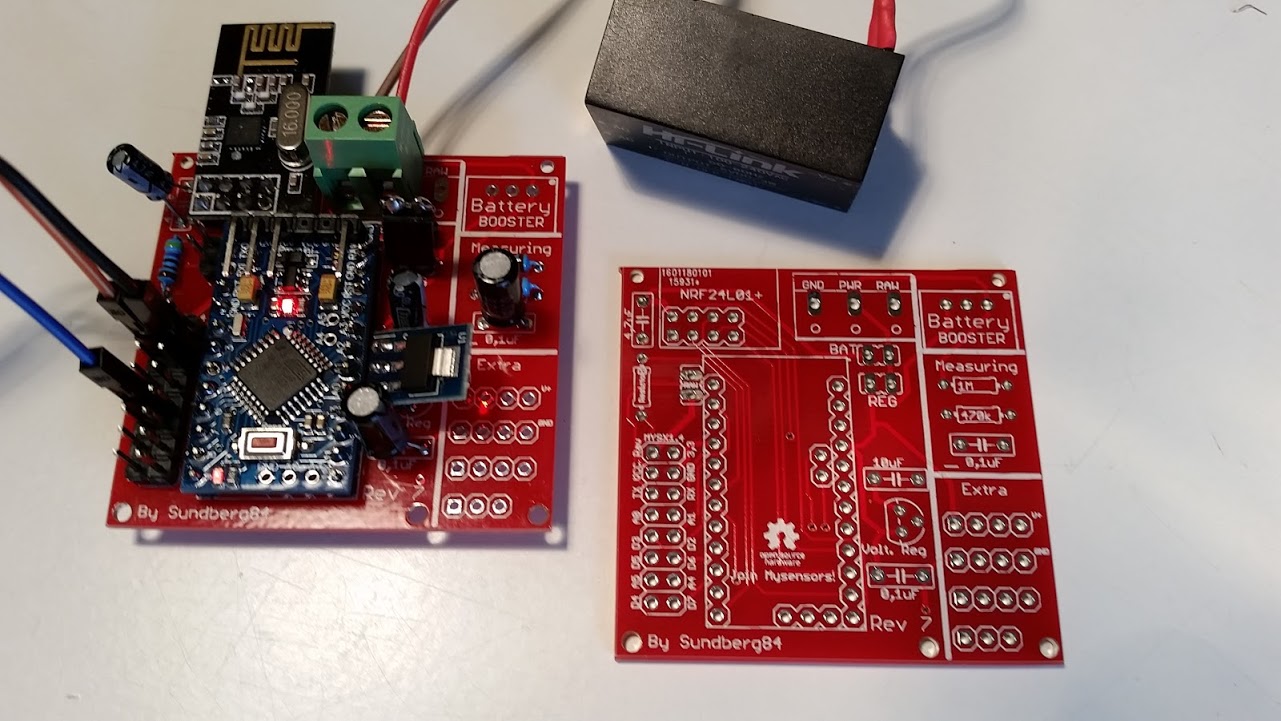
Sounds good @ErrK - dont forget to power it through REG and not RAW on the PCB and add a jumper on REG since it wont work if you use the same setup as in the images and remove voltage regulator.
Controller: Proxmox VM - Home Assistant
MySensors GW: Arduino Uno - W5100 Ethernet, Gw Shield Nrf24l01+ 2,4Ghz
MySensors GW: Arduino Uno - Gw Shield RFM69, 433mhz
RFLink GW - Arduino Mega + RFLink Shield, 433mhz -
Sounds good @ErrK - dont forget to power it through REG and not RAW on the PCB and add a jumper on REG since it wont work if you use the same setup as in the images and remove voltage regulator.
Thank you @sundberg84. I will think of that.
-
@Barna - I just wanted to make it smaller, with the radio not sticking out so much.
I ordered them a while ago, so if they made it out of china before their new year I think it will be tested soon. -
Nice. @dark-nico
The main concern is the new placement of caps and voltage divider - I hope they fit in between the radio and screw terminal. Should not be a problem - but you know, always nice to see it IRL. Might be good to solder them first before radio, arduino and screw terminal. -
Ok, I'll do that.
My main problem is that I haven't received both my booster and my 5->3.3 reg. :disappointed:
So I can test Batt version by bypassing the booster, but it will not tell us if the reg placement is ok.
I'll dig in my "donor harware" if I can find a reg. -
@dark-nico - You know its easy to cut the PCB to make it smaller? Using it as 5v you can remove the right battery part:
Either cut with a knife and brake:
https://www.youtube.com/watch?v=SiC-_g3iNb8Or sometimes i just use a saw (before components are added) - might not be recommended ;)
Controller: Proxmox VM - Home Assistant
MySensors GW: Arduino Uno - W5100 Ethernet, Gw Shield Nrf24l01+ 2,4Ghz
MySensors GW: Arduino Uno - Gw Shield RFM69, 433mhz
RFLink GW - Arduino Mega + RFLink Shield, 433mhz -
@dark-nico - You know its easy to cut the PCB to make it smaller? Using it as 5v you can remove the right battery part:
Either cut with a knife and brake:
https://www.youtube.com/watch?v=SiC-_g3iNb8Or sometimes i just use a saw (before components are added) - might not be recommended ;)
@sundberg84 - Yes I know that I can cut that part, but I think this one will be my test board with all this option, including the battery parts.
However I'll keep the video method in mind, I was thinking about using a dremel, but, it seems cleaner. -
@dark-nico Ok, have not tested adding both Bat and reg/5v posibilities at the same time. Might be that 5v travels backwards towards the booster... try it out, but as I said, not tested.
-
@sundberg84 : I have also received the rev 7 from DirtyPCB and learned how to solder. Very nice and flexible design !
Perfect for a Newbie :). Thnaks a lot for sharing -
Hi!
No problems! Makes me glad to see i made something usefull for others :)
Interesting setup you got the with the HLK as power :+1: -
-
@dakipro If you "download all project files" @ https://www.openhardware.io/you will get all files (Eagles, Gerber (run with Iteads CAM job) and other stuff).

