Skip to content
  • MySensors
  • OpenHardware.io
  • Categories
  • Recent
  • Tags
  • Popular
Skins
  • Light
  • Brite
  • Cerulean
  • Cosmo
  • Flatly
  • Journal
  • Litera
  • Lumen
  • Lux
  • Materia
  • Minty
  • Morph
  • Pulse
  • Sandstone
  • Simplex
  • Sketchy
  • Spacelab
  • United
  • Yeti
  • Zephyr
  • Dark
  • Cyborg
  • Darkly
  • Quartz
  • Slate
  • Solar
  • Superhero
  • Vapor

  • Default (No Skin)
  • No Skin
Collapse
Brand Logo
  1. Home
  2. OpenHardware.io
  3. 💬 Easy/Newbie PCB for MySensors

💬 Easy/Newbie PCB for MySensors

Scheduled Pinned Locked Moved OpenHardware.io
mysensorsbatteryeasynewbiepcbmysx
716 Posts 111 Posters 306.0k Views 93 Watching
  • Oldest to Newest
  • Newest to Oldest
  • Most Votes
Reply
  • Reply as topic
Log in to reply
This topic has been deleted. Only users with topic management privileges can see it.
  • gohanG Offline
    gohanG Offline
    gohan
    Mod
    wrote on last edited by
    #565

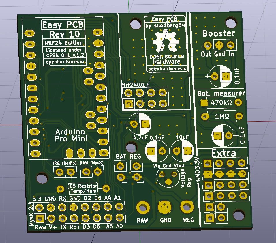
    how about swapping the Extra and Booster section? It makes it cleaner to connect the extra pins to the pro mini.

    dbemowskD 1 Reply Last reply
    0
    • sundberg84S sundberg84

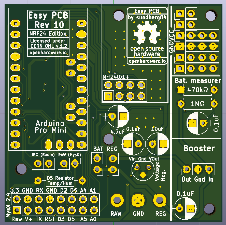
      @dbemowsk what I'm worried about is the booster so close to the radio. What do you think @dbemowsk @scalz @Nca78 ?

      alt text

      scalzS Offline
      scalzS Offline
      scalz
      Hardware Contributor
      wrote on last edited by
      #566

      @sundberg84 i think you already know the answer 😉 (not great regarding emi radiation for example,especially with cheap regulators and inductors.., one downside of relying on external parts,modules but i know your point it's for noobs..)
      I seem to see another thing for your nrf ant, not sure if your nrf 24 goes outside the pcb,if it doesn't then this means you have gnd pour under the ant, not great too in this case

      1 Reply Last reply
      0
      • gohanG gohan

        how about swapping the Extra and Booster section? It makes it cleaner to connect the extra pins to the pro mini.

        dbemowskD Offline
        dbemowskD Offline
        dbemowsk
        wrote on last edited by
        #567

        @gohan & @sundberg84 For that matter, what about just swapping the Bat.measurer and the booster. You are going to get interference with the inductor being directly next to the antenna.

        Vera Plus running UI7 with MySensors, Sonoffs and 1-Wire devices
        Visit my website for more Bits, Bytes and Ramblings from me: http://dan.bemowski.info/

        1 Reply Last reply
        0
        • sundberg84S Offline
          sundberg84S Offline
          sundberg84
          Hardware Contributor
          wrote on last edited by sundberg84
          #568

          Thanks guys! (@scalz @gohan @dbemowsk !)
          I think I will relocate the booster... should have thought about that before.
          The NRF antenna goes outside the PCB just like rev 9 so no ground plain for the antenna in normal cases. I might revert it back to allow the PCB to be in range for all directions. Good point.

          I will start with to swap extra and booster to get as much space in between the antenna and inductor.

          Controller: Proxmox VM - Home Assistant
          MySensors GW: Arduino Uno - W5100 Ethernet, Gw Shield Nrf24l01+ 2,4Ghz
          MySensors GW: Arduino Uno - Gw Shield RFM69, 433mhz
          RFLink GW - Arduino Mega + RFLink Shield, 433mhz

          1 Reply Last reply
          2
          • sundberg84S Offline
            sundberg84S Offline
            sundberg84
            Hardware Contributor
            wrote on last edited by
            #569

            Something like this...

            0_1521917114887_7092eb47-33ac-4a9c-baf9-c3fd3cd5c658-image.png

            Controller: Proxmox VM - Home Assistant
            MySensors GW: Arduino Uno - W5100 Ethernet, Gw Shield Nrf24l01+ 2,4Ghz
            MySensors GW: Arduino Uno - Gw Shield RFM69, 433mhz
            RFLink GW - Arduino Mega + RFLink Shield, 433mhz

            1 Reply Last reply
            1
            • dbemowskD Offline
              dbemowskD Offline
              dbemowsk
              wrote on last edited by
              #570

              Would something like this be possible? It would give users that little bit of extra room in the proto area.
              0_1521918858785_911e7f1a-5943-4a40-a49c-e99853681070-image.png

              Vera Plus running UI7 with MySensors, Sonoffs and 1-Wire devices
              Visit my website for more Bits, Bytes and Ramblings from me: http://dan.bemowski.info/

              1 Reply Last reply
              2
              • sundberg84S Offline
                sundberg84S Offline
                sundberg84
                Hardware Contributor
                wrote on last edited by
                #571

                Hi all!

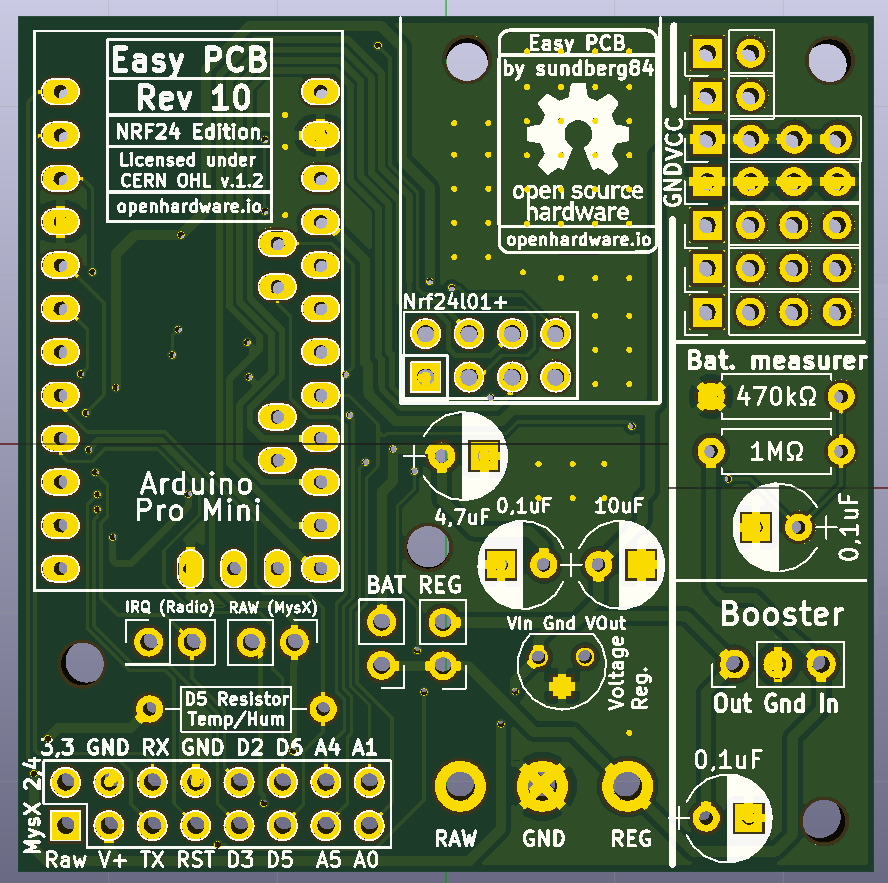
                This has now been update to Rev 10.
                New revision has been sent to PCB manufacturer but It will take some days for them to update their Gerber. (When you order, make sure it says M.Rev 6!
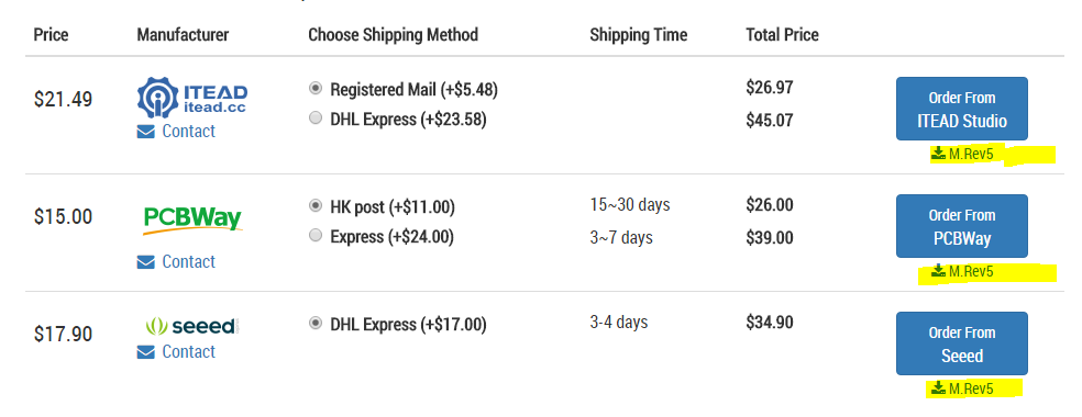
                0_1528107591933_8daa3f55-a3e9-456a-86fe-cbb70d43c8fd-image.png

                Openhardware page has been updated, let me know if you find anything strange.

                RFM69 version will be updated soon as well.

                Controller: Proxmox VM - Home Assistant
                MySensors GW: Arduino Uno - W5100 Ethernet, Gw Shield Nrf24l01+ 2,4Ghz
                MySensors GW: Arduino Uno - Gw Shield RFM69, 433mhz
                RFLink GW - Arduino Mega + RFLink Shield, 433mhz

                1 Reply Last reply
                4
                • A Offline
                  A Offline
                  APL2017
                  wrote on last edited by
                  #572

                  Can you please share design of version 9 of the Easy PCB NRF24 edition. I bought 10 pieces a while ago but just decided to use couple. Thank you.

                  sundberg84S 1 Reply Last reply
                  0
                  • A APL2017

                    Can you please share design of version 9 of the Easy PCB NRF24 edition. I bought 10 pieces a while ago but just decided to use couple. Thank you.

                    sundberg84S Offline
                    sundberg84S Offline
                    sundberg84
                    Hardware Contributor
                    wrote on last edited by sundberg84
                    #573

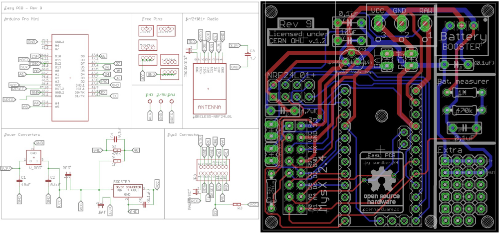
                    @apl2017 what kind of info are you looking for ? Schematics ?
                    0_1528351654852_Rev9 Schem.jpg

                    Controller: Proxmox VM - Home Assistant
                    MySensors GW: Arduino Uno - W5100 Ethernet, Gw Shield Nrf24l01+ 2,4Ghz
                    MySensors GW: Arduino Uno - Gw Shield RFM69, 433mhz
                    RFLink GW - Arduino Mega + RFLink Shield, 433mhz

                    1 Reply Last reply
                    0
                    • A Offline
                      A Offline
                      APL2017
                      wrote on last edited by
                      #574

                      Just schematic and board layout, exactly what you placed, if possible in a bit better resolution. Thanks a lot!

                      sundberg84S 1 Reply Last reply
                      0
                      • A APL2017

                        Just schematic and board layout, exactly what you placed, if possible in a bit better resolution. Thanks a lot!

                        sundberg84S Offline
                        sundberg84S Offline
                        sundberg84
                        Hardware Contributor
                        wrote on last edited by
                        #575

                        @apl2017 traveling for my work until next week but will post then.

                        Controller: Proxmox VM - Home Assistant
                        MySensors GW: Arduino Uno - W5100 Ethernet, Gw Shield Nrf24l01+ 2,4Ghz
                        MySensors GW: Arduino Uno - Gw Shield RFM69, 433mhz
                        RFLink GW - Arduino Mega + RFLink Shield, 433mhz

                        1 Reply Last reply
                        0
                        • M Offline
                          M Offline
                          Mister_ik
                          wrote on last edited by
                          #576

                          @sundberg84 I just finished my first battery sensor node based on the Easy PCB Rev 9. I have two questions i hope you can help me with:

                          The first is about the battery measurement. Because i didn't have a 0.1 uf lying around i used an 0.2 uf capacitor. I am using the following script to measure the battery.

                          //=========================
                          // BATTERY VOLTAGE DIVIDER SETUP
                          // 1M, 470K divider across battery and using internal ADC ref of 1.1V
                          // Sense point is bypassed with 0.1 uF cap to reduce noise at that point
                          // ((1e6+470e3)/470e3)*1.1 = Vmax = 3.44 Volts
                          // 3.44/1023 = Volts per bit = 0.003363075
                          #define VBAT_PER_BITS 0.003363075  
                          #define VMIN 1.9                                  //  Vmin (radio Min Volt)=1.9V (564v)
                          #define VMAX 3.0                                  //  Vmax = (2xAA bat)=3.0V (892v)
                          int batteryPcnt = 0;                              // Calc value for battery %
                          int batLoop = 0;                                  // Loop to help calc average
                          int batArray[3];                                  // Array to store value for average calc.
                          int BATTERY_SENSE_PIN = A0;                       // select the input pin for the battery sense point
                          //=========================   
                          
                          
                             // Calculate the battery in %
                             float Vbat  = sensorValue * VBAT_PER_BITS;
                             int batteryPcnt = static_cast<int>(((Vbat-VMIN)/(VMAX-VMIN))*100.);
                             Serial.print("Battery percent: "); Serial.print(batteryPcnt); Serial.println(" %");  
                          

                          Do i need to change anything in the formula? Because i getting reading around the 130%

                          Requesting temperature...DONE
                          Temperatuur : 26.62 Degrees C
                          11935 TSF:MSG:SEND,25-25-0-0,s=5,c=1,t=0,pt=7,l=5,sg=0,ft=0,st=OK:26.6
                          Battery percent: 131 %
                          Battery Voltage: 3.35 V
                          Sleep...
                          12945 MCO:SLP:MS=900000,SMS=0,I1=0,M1=1,I2=254,M2=1
                          12955 TSF:TDI:TSL


                          If i use the following method:

                          //----
                             // 1M, 470K divider across battery and using internal ADC ref of 1.1V
                             // Sense point is bypassed with 0.1 uF cap to reduce noise at that point
                             // ((1e6+470e3)/470e3)*1.1 = Vmax = 3.44 Volts
                             // 3.44/1023 = Volts per bit = 0.003363075
                             float batteryV  = sensorValue * 0.003363075;
                             int batteryPcntNEW = sensorValue / 10;
                          
                             Serial.print("Battery percent: ");
                             Serial.print(batteryPcntNEW);
                             Serial.println(" %");
                          //----
                          

                          I am getting: (this is expected, because batteries are new)

                          Battery percent: 99 %
                          Sleep...
                          12945 MCO:SLP:MS=900000,SMS=0,I1=0,M1=1,I2=254,M2=1
                          12955 TSF:TDI:TSL


                          My second question is about casing: any tips on which case to use which fit your board and a battery pack? and is as small as possible? Do you perhaps have links of your favourite (Chinese) sellers?

                          Nca78N sundberg84S 2 Replies Last reply
                          0
                          • M Mister_ik

                            @sundberg84 I just finished my first battery sensor node based on the Easy PCB Rev 9. I have two questions i hope you can help me with:

                            The first is about the battery measurement. Because i didn't have a 0.1 uf lying around i used an 0.2 uf capacitor. I am using the following script to measure the battery.

                            //=========================
                            // BATTERY VOLTAGE DIVIDER SETUP
                            // 1M, 470K divider across battery and using internal ADC ref of 1.1V
                            // Sense point is bypassed with 0.1 uF cap to reduce noise at that point
                            // ((1e6+470e3)/470e3)*1.1 = Vmax = 3.44 Volts
                            // 3.44/1023 = Volts per bit = 0.003363075
                            #define VBAT_PER_BITS 0.003363075  
                            #define VMIN 1.9                                  //  Vmin (radio Min Volt)=1.9V (564v)
                            #define VMAX 3.0                                  //  Vmax = (2xAA bat)=3.0V (892v)
                            int batteryPcnt = 0;                              // Calc value for battery %
                            int batLoop = 0;                                  // Loop to help calc average
                            int batArray[3];                                  // Array to store value for average calc.
                            int BATTERY_SENSE_PIN = A0;                       // select the input pin for the battery sense point
                            //=========================   
                            
                            
                               // Calculate the battery in %
                               float Vbat  = sensorValue * VBAT_PER_BITS;
                               int batteryPcnt = static_cast<int>(((Vbat-VMIN)/(VMAX-VMIN))*100.);
                               Serial.print("Battery percent: "); Serial.print(batteryPcnt); Serial.println(" %");  
                            

                            Do i need to change anything in the formula? Because i getting reading around the 130%

                            Requesting temperature...DONE
                            Temperatuur : 26.62 Degrees C
                            11935 TSF:MSG:SEND,25-25-0-0,s=5,c=1,t=0,pt=7,l=5,sg=0,ft=0,st=OK:26.6
                            Battery percent: 131 %
                            Battery Voltage: 3.35 V
                            Sleep...
                            12945 MCO:SLP:MS=900000,SMS=0,I1=0,M1=1,I2=254,M2=1
                            12955 TSF:TDI:TSL


                            If i use the following method:

                            //----
                               // 1M, 470K divider across battery and using internal ADC ref of 1.1V
                               // Sense point is bypassed with 0.1 uF cap to reduce noise at that point
                               // ((1e6+470e3)/470e3)*1.1 = Vmax = 3.44 Volts
                               // 3.44/1023 = Volts per bit = 0.003363075
                               float batteryV  = sensorValue * 0.003363075;
                               int batteryPcntNEW = sensorValue / 10;
                            
                               Serial.print("Battery percent: ");
                               Serial.print(batteryPcntNEW);
                               Serial.println(" %");
                            //----
                            

                            I am getting: (this is expected, because batteries are new)

                            Battery percent: 99 %
                            Sleep...
                            12945 MCO:SLP:MS=900000,SMS=0,I1=0,M1=1,I2=254,M2=1
                            12955 TSF:TDI:TSL


                            My second question is about casing: any tips on which case to use which fit your board and a battery pack? and is as small as possible? Do you perhaps have links of your favourite (Chinese) sellers?

                            Nca78N Offline
                            Nca78N Offline
                            Nca78
                            Hardware Contributor
                            wrote on last edited by
                            #577

                            @mister_ik said in 💬 Easy/Newbie PCB for MySensors:

                            @sundberg84 I just finished my first battery sensor node based on the Easy PCB Rev 9. I have two questions i hope you can help me with:

                            The first is about the battery measurement. Because i didn't have a 0.1 uf lying around i used an 0.2 uf capacitor. I am using the following script to measure the battery.

                            Do i need to change anything in the formula? Because i getting reading around the 130%

                            Hello, this is normal as your maximum voltage is set at 3V, while initial voltage of an alkaline AA/AAA cell can be a bit over 1.6V. But voltage will quickly drop toward 1.5V (much faster than remaining capacity), so the best instead of changing the maximum voltage is to check the value of batteryPcnt and if it's over 100, just set it to 100.
                            Make sure the VBAT_PER_BITS makes you read a voltage that matches the voltage you read with your multimeter, else fix it. Each Atmega is different so you need to calibrate each board.

                            For the capacitor it's not a problem, it's just made to stabilize the voltage as it's very sensible to electrical noise. Twice the value will be good enough for this job :)

                            1 Reply Last reply
                            0
                            • M Mister_ik

                              @sundberg84 I just finished my first battery sensor node based on the Easy PCB Rev 9. I have two questions i hope you can help me with:

                              The first is about the battery measurement. Because i didn't have a 0.1 uf lying around i used an 0.2 uf capacitor. I am using the following script to measure the battery.

                              //=========================
                              // BATTERY VOLTAGE DIVIDER SETUP
                              // 1M, 470K divider across battery and using internal ADC ref of 1.1V
                              // Sense point is bypassed with 0.1 uF cap to reduce noise at that point
                              // ((1e6+470e3)/470e3)*1.1 = Vmax = 3.44 Volts
                              // 3.44/1023 = Volts per bit = 0.003363075
                              #define VBAT_PER_BITS 0.003363075  
                              #define VMIN 1.9                                  //  Vmin (radio Min Volt)=1.9V (564v)
                              #define VMAX 3.0                                  //  Vmax = (2xAA bat)=3.0V (892v)
                              int batteryPcnt = 0;                              // Calc value for battery %
                              int batLoop = 0;                                  // Loop to help calc average
                              int batArray[3];                                  // Array to store value for average calc.
                              int BATTERY_SENSE_PIN = A0;                       // select the input pin for the battery sense point
                              //=========================   
                              
                              
                                 // Calculate the battery in %
                                 float Vbat  = sensorValue * VBAT_PER_BITS;
                                 int batteryPcnt = static_cast<int>(((Vbat-VMIN)/(VMAX-VMIN))*100.);
                                 Serial.print("Battery percent: "); Serial.print(batteryPcnt); Serial.println(" %");  
                              

                              Do i need to change anything in the formula? Because i getting reading around the 130%

                              Requesting temperature...DONE
                              Temperatuur : 26.62 Degrees C
                              11935 TSF:MSG:SEND,25-25-0-0,s=5,c=1,t=0,pt=7,l=5,sg=0,ft=0,st=OK:26.6
                              Battery percent: 131 %
                              Battery Voltage: 3.35 V
                              Sleep...
                              12945 MCO:SLP:MS=900000,SMS=0,I1=0,M1=1,I2=254,M2=1
                              12955 TSF:TDI:TSL


                              If i use the following method:

                              //----
                                 // 1M, 470K divider across battery and using internal ADC ref of 1.1V
                                 // Sense point is bypassed with 0.1 uF cap to reduce noise at that point
                                 // ((1e6+470e3)/470e3)*1.1 = Vmax = 3.44 Volts
                                 // 3.44/1023 = Volts per bit = 0.003363075
                                 float batteryV  = sensorValue * 0.003363075;
                                 int batteryPcntNEW = sensorValue / 10;
                              
                                 Serial.print("Battery percent: ");
                                 Serial.print(batteryPcntNEW);
                                 Serial.println(" %");
                              //----
                              

                              I am getting: (this is expected, because batteries are new)

                              Battery percent: 99 %
                              Sleep...
                              12945 MCO:SLP:MS=900000,SMS=0,I1=0,M1=1,I2=254,M2=1
                              12955 TSF:TDI:TSL


                              My second question is about casing: any tips on which case to use which fit your board and a battery pack? and is as small as possible? Do you perhaps have links of your favourite (Chinese) sellers?

                              sundberg84S Offline
                              sundberg84S Offline
                              sundberg84
                              Hardware Contributor
                              wrote on last edited by sundberg84
                              #578

                              @Nca78 thanks for the help/answer. 😀 About the case I'm using some plastic electronic cases from my hardware shop but @ openhardware you will find some links to 3d projects.

                              Let us know @Mister_ik if you need anything else.

                              Controller: Proxmox VM - Home Assistant
                              MySensors GW: Arduino Uno - W5100 Ethernet, Gw Shield Nrf24l01+ 2,4Ghz
                              MySensors GW: Arduino Uno - Gw Shield RFM69, 433mhz
                              RFLink GW - Arduino Mega + RFLink Shield, 433mhz

                              1 Reply Last reply
                              0
                              • M Offline
                                M Offline
                                mickecarlsson
                                wrote on last edited by
                                #579

                                No sign of the new revision yet:

                                0_1528708713299_3aff98ea-8698-4521-8901-7093de8edb7e-image.png

                                sundberg84S 1 Reply Last reply
                                0
                                • M mickecarlsson

                                  No sign of the new revision yet:

                                  0_1528708713299_3aff98ea-8698-4521-8901-7093de8edb7e-image.png

                                  sundberg84S Offline
                                  sundberg84S Offline
                                  sundberg84
                                  Hardware Contributor
                                  wrote on last edited by
                                  #580

                                  @mickecarlsson - not on the RFM69 version, no. PCBway has updated the NRF24 version so a good sign.
                                  Something went wrong with the update of the RFM69 version so I had to activate it 21hours ago:

                                  0_1528709688387_8c18a333-5e8f-4f63-8fd5-be26c87c4b18-image.png

                                  Lets hope PCBway picks this up today.

                                  Controller: Proxmox VM - Home Assistant
                                  MySensors GW: Arduino Uno - W5100 Ethernet, Gw Shield Nrf24l01+ 2,4Ghz
                                  MySensors GW: Arduino Uno - Gw Shield RFM69, 433mhz
                                  RFLink GW - Arduino Mega + RFLink Shield, 433mhz

                                  M 1 Reply Last reply
                                  0
                                  • sundberg84S sundberg84

                                    @mickecarlsson - not on the RFM69 version, no. PCBway has updated the NRF24 version so a good sign.
                                    Something went wrong with the update of the RFM69 version so I had to activate it 21hours ago:

                                    0_1528709688387_8c18a333-5e8f-4f63-8fd5-be26c87c4b18-image.png

                                    Lets hope PCBway picks this up today.

                                    M Offline
                                    M Offline
                                    mickecarlsson
                                    wrote on last edited by
                                    #581

                                    @sundberg84
                                    OK, good news. I will check it tomorrow and hopefully order a batch (or two).

                                    1 Reply Last reply
                                    0
                                    • M Offline
                                      M Offline
                                      mickecarlsson
                                      wrote on last edited by
                                      #582

                                      Still no rev 6 on itead or pcbway for rfm69 version :-(

                                      sundberg84S 1 Reply Last reply
                                      0
                                      • M mickecarlsson

                                        Still no rev 6 on itead or pcbway for rfm69 version :-(

                                        sundberg84S Offline
                                        sundberg84S Offline
                                        sundberg84
                                        Hardware Contributor
                                        wrote on last edited by
                                        #583

                                        @mickecarlsson no something went wrong so Rev 5 is ok to order! This is easy rev 10!

                                        Controller: Proxmox VM - Home Assistant
                                        MySensors GW: Arduino Uno - W5100 Ethernet, Gw Shield Nrf24l01+ 2,4Ghz
                                        MySensors GW: Arduino Uno - Gw Shield RFM69, 433mhz
                                        RFLink GW - Arduino Mega + RFLink Shield, 433mhz

                                        1 Reply Last reply
                                        0
                                        • ร Offline
                                          ร Offline
                                          รอเรือ
                                          wrote on last edited by รอเรือ
                                          #584

                                          Hello @sundberg84

                                          What if feeding a Pro Mini 3.3V (EasyPCB Nrf24l01+ edition rev 10) with regulated power on RAW. (I have 5 VDC). I guess I can feed the radio via the VCC terminal instead of using an external voltage regulator. Can the EasyPCB be used in such a setup?

                                          Edit: To answer my own question. I should RTFM :facepunch:

                                          It states clearly that:

                                          "(If you are using regulated 3.3v, use 5v instructions but skip the voltage regulator and bypass this with a jumper between Vin and Vout"

                                          Thanks anyway!

                                          franz-unixF 1 Reply Last reply
                                          2
                                          Reply
                                          • Reply as topic
                                          Log in to reply
                                          • Oldest to Newest
                                          • Newest to Oldest
                                          • Most Votes


                                          7

                                          Online

                                          11.7k

                                          Users

                                          11.2k

                                          Topics

                                          113.0k

                                          Posts


                                          Copyright 2019 TBD   |   Forum Guidelines   |   Privacy Policy   |   Terms of Service
                                          • Login

                                          • Don't have an account? Register

                                          • Login or register to search.
                                          • First post
                                            Last post
                                          0
                                          • MySensors
                                          • OpenHardware.io
                                          • Categories
                                          • Recent
                                          • Tags
                                          • Popular