💬 Easy/Newbie PCB for MySensors


  • No sign of the new revision yet:

    0_1528708713299_3aff98ea-8698-4521-8901-7093de8edb7e-image.png


  • Hardware Contributor

    @mickecarlsson - not on the RFM69 version, no. PCBway has updated the NRF24 version so a good sign.
    Something went wrong with the update of the RFM69 version so I had to activate it 21hours ago:

    0_1528709688387_8c18a333-5e8f-4f63-8fd5-be26c87c4b18-image.png

    Lets hope PCBway picks this up today.


  • @sundberg84
    OK, good news. I will check it tomorrow and hopefully order a batch (or two).


  • Still no rev 6 on itead or pcbway for rfm69 version 😞


  • Hardware Contributor

    @mickecarlsson no something went wrong so Rev 5 is ok to order! This is easy rev 10!


  • Hello @sundberg84

    What if feeding a Pro Mini 3.3V (EasyPCB Nrf24l01+ edition rev 10) with regulated power on RAW. (I have 5 VDC). I guess I can feed the radio via the VCC terminal instead of using an external voltage regulator. Can the EasyPCB be used in such a setup?

    Edit: To answer my own question. I should RTFM 👊

    It states clearly that:

    "(If you are using regulated 3.3v, use 5v instructions but skip the voltage regulator and bypass this with a jumper between Vin and Vout"

    Thanks anyway!


  • This post is deleted!


  • @รอเร-อ I have a similar need, but not exactly the same.
    My power route is:
    18650 Lipo (2.7 - 4.2 V) -> TP4056 (charger) -> Booster (5V) -> Raw pin of pro mini 3.3V -> Vcc of pro mini 3.3V -> Radio (NRF24)

    In my case the easy newbie pcb is not directly suitable because the Vout of the Booster is connected to Vcc instead of raw.

    So my idea is to use a modified version of the easy newbie pcb with the schematic posted here
    in order to have more flexibility in the power options.

    Actually I don't have the skills to design a pcb, but maybe, if the idea is good, someone else could design it.

    This schematic is compatible with all the power options actually supported by the easy newbie pcb, and supports also new possibility, simply changing a couple of jumpers


  • Hardware Contributor

    Hello @franz-unix, can't you just bend the output pin of the booster at 90° and solder a wire from it to the raw pin ?


  • @nca78 Yes it should work.

    If I connect the output of the tp4056 to the gnd and reg input of the screw terminal of the easy newbie pcb and then I run a wire from the Vout of the booster to the raw input of the screw terminal, the final result is also quite clean and it is not necessary to solder the wire directly on the pro mini.

    I think that, in this case, the reg jumper must be NOT shortened.


  • Hi,

    I ordered 10 PCBs using "Order from PCBWay" button. It only asked me about PayPal card and din't require any registration on PCBWay. So, everything looks good, PayPal transaction is completed. Can somebody tell me please how can I track it? Probably I'm missing tracking option somewhere... Thank you!

    P.S.
    Cant wait to try it out. 🙂


  • Hardware Contributor

    @zelen I'm not sure. You didn't receive any email? I normally get a email once they are finished and shipped with tracking.


  • This post is deleted!


  • @sundberg84 thank you for clarification. I expected email right after making an order. So, I will wait for finishing production and shipment.


  • I use some of old rev8 boards. I have noticed that I use a ceramic capacitor instead of an electric capacitor compared to the images for the battery measurement. Does it matter? Or should I replace the ceramic capacitor (104) with an electric capacitor?


  • Hardware Contributor

    @harrdy should work just fine.


  • Mod

    @harrdy remember to take a few readings and average out the battery value


  • Hello @sundberg84, I would like to buy the Easy/Newbie PCB for MySensors but I have a few questions
    I want to use it the 5V Arduino Pro mini not the 3V version
    I also want to use the battery monitor
    Is it ok or should I modify "something"
    Also all the pcbs have the battery "expansion: or not?
    Thanks, Emmanuel


  • Mod

    Why would you want to use the 5v arduino on batteries?


  • Hardware Contributor

    @manos

    I want to use it the 5V Arduino Pro mini not the 3V version

    Then you need to use the nrf24l01+ version, that works fine - the RFM69 version needs a 3.3v Pro Mini only.

    I also want to use the battery monitor

    As @gohan said - don't use batteries on a 5v node. Use a 3.3v because it will use up your batteries very quickly. See the guides i have on openhardware for different modes on my PCB.

    Is it ok or should I modify "something"
    Also all the pcbs have the battery "expansion: or not?

    "something" is hard to understand, you can modify i many different ways depending on what you want to do. All the basic "modifications" can be found if you read the project page on openhardware.io


  • @sundberg84 thanks for your response
    If I don't care about battery consumption can I still view and use the battery monitor to be alarmed when battery is empty?


  • Hardware Contributor

    @manos yes you can.


  • This post is deleted!


  • Hello @sundberg84. I watched your video 9+ 'MySensors Battery Node 2xAA - EasyPCB (Nrf24l01+)and Temp Sensor' . I have two questions about this video:

    • I noticed you connected the tempsensor to the extra prototype part of the board, but i could not see in the video how you connected signal pin of the sensor to the arduino.
    • you added a resistor to D5 Temp/Hum, but you did not add the sensor to the mysX2.4 part of the board. Why is that?

  • Hardware Contributor

    @mister_ik said in 💬 Easy/Newbie PCB for MySensors:

    Hello @sundberg84. I watched your video 9+ 'MySensors Battery Node 2xAA - EasyPCB (Nrf24l01+)and Temp Sensor' . I have two questions about this video:

    • I noticed you connected the tempsensor to the extra prototype part of the board, but i could not see in the video how you connected signal pin of the sensor to the arduino.
    • you added a resistor to D5 Temp/Hum, but you did not add the sensor to the mysX2.4 part of the board. Why is that?

    I connect it on the back with a normal wire to D5 resistor input. So both of your observations above are correct.


  • @sundberg84 yes i thought so, but i want to make sure. I have some Rev 10 boards and i was working on a node for my bathroom with a DHT11 sensor. I had some problems with it, therefore watching your video. But it looks like the step up booster was not working correctly. Unfortunately removing the booster i damaged the board because with a new booster the arduino won't get power any more. So this board only works without the booster (and reg jumper connected). Any idea how long this setup (with removed led on arduino) will last on batteries?


  • Hardware Contributor

    @mister_ik - well, 2-4 weeks more or less unless you reprogram the fuses and bootloader.


  • @sundberg84 ooh that is not very long ..i hoped for a couple of months....but then I should consider this board as depreciated and build a new one and use this for development. Thanks for your reaction.


  • Hardware Contributor

    @mister_ik you can always use wired to repair the damaged tracks.


  • @sundberg84, thanks so much for this board, I bought 10 of them. This has made my sensor projects much easier and they look better too! I think I will get some of the RFM69 version next.

    I have a lot of gel lead acid batteries (the 7.2AH type often used in UPSs), and I have been running an earlier prototype off that. I have now just changed over to your board and this is how I modified it to work the way I wanted:

    • Cut the track circled
    • Hard wired from the regulator side of the battery jumper to VCC on the Pro Mini
    • Bridged the booster In to Out
    • Changed the battery measuring resistors to 12k/180k for greater range

    This enabled me to run the board off 12V, keep an eye on the battery voltage, and run the rest from the LE33 regulator. It seems to be managing so far, with 3 x DS18B20 temperature sensors. I'm monitoring the fridge outside, inside and freezer temperatures with this module.

    0_1540535341222_combined board mods 3V3 Reg_20181026_170050.jpg


  • This post is deleted!

  • Hardware Contributor

    @ajay100 - Hi!
    Really nice to see you found your way of using my PCB, its just the way I want it 🙂
    I tried to follow along here, are you using the LEd33 to convert 12v to 3.3v? I guess you tried RAW and the voltage regulator on your pro mini and found out it was bad due to cheap clones?

    If you cut the trace just above the volt.reg and put a jumper from REG to Vin on the Volt reg, and added a jumper from Bat (top) to Reg (top) you would also feed everything with whatever comes out from the LE33.

    0_1540545775768_55d6843d-eb8d-4902-940b-d16101885538-image.png (I think)


  • @sundberg84, I've just tried it and that is a better solution than mine for running everything from the LE33. Thanks for taking the time to work that out!

    Cheers - Andrew


  • Hey @sundberg84 I just saw the new rev.10, congratulations on the upgrade!
    I still have a bunch of rev 9, do you happen to have images/manual for previous version somewhere? link or a pdf?
    Thanks!


  • Hardware Contributor

    @dakipro - sorry, everything was saved here on oh.
    Is there something special you need? I can maybe send it to you, like schematics or what are you looking for?


  • Admin

    Zip files with old revisions get stored on openhardware.io but is not exposed in any good way for the end user today. They're only accessible for the manufacturers.

    I will see if I can show it somehow. Maybe a new tab on the project page listing old revisions with download links.


  • Admin


  • Thank you @hek , I think this might be useful feature
    I however do not see any data in there, is it something for project owner to allow?
    I tried both as guest and as logged inn, I do see the rows, but no data in fields, screenshot:

    0_1542407389061_Screenshot 2018-11-16 23.28.04.png

    @sundberg84 nothing special about now, I figured it out based on older projects. But since I still have about dosen of boards, I will probably need documentation few years from now, so was just hoping to have it somewhere easily available 🙂 Like a downloaded pdf or something


  • Admin

    Thanks for reporting @dakipro. It seems to have been a caching issue in the service. Should not appear again.


  • Me too i still have a bunch of rev 9. Where can i have all the old informations for this rev? I need to see the old webpage with instructions. Thank you !


  • Thanks @hek it is certainly helpful. However the most powerful information is actually in the description page, about how to use the board, how to wire it up for different use cases etc. I suppose a previous version of the information tab is not available?
    If it could be archived (maybe even linked somewhere) it would be really helpful!


  • Admin

    The documentation at the time of the created revision is actually included in the zip as README.md (markdown).
    You should be able to view the file properly formatted in an md-editor or online using I.e.. https://dillinger.io/

    Uploaded images was never included in the revision dumps unfortunately.


  • Ooops, my bad then 😞 I was pretty sure I checked readme.md file, but apparently I got confused.
    Thanks a million!


  • I am also looking for documentation for Rev. 9 that I purchased. The link with revisions that was provided: https://www.openhardware.io/view/4/EasyNewbie-PCB-for-MySensors#tabs-revisions
    lists revisions 1-7, but not 9. All I need is readable schematic and PCB layout in PDF. Thanks.


  • Mod

    @apl2017 I don't know where the revision numbering comes from, but I believe the rev9 you are talking about is called rev5 on the revisions tab.

    Rev 10 was created 2018-06-04. That date matches with rev6 on the revisions tab.

    Perhaps @sundberg84 knows why there are two sets of revision numbers?


  • What software was used to develop this board? My latest KiCad does not read schematic from Rev. 5 ZIP file. All I need is a simple PDF...


  • Hardware Contributor

    @apl2017 - Rev 10 = Kicad, but all below is Eagles.

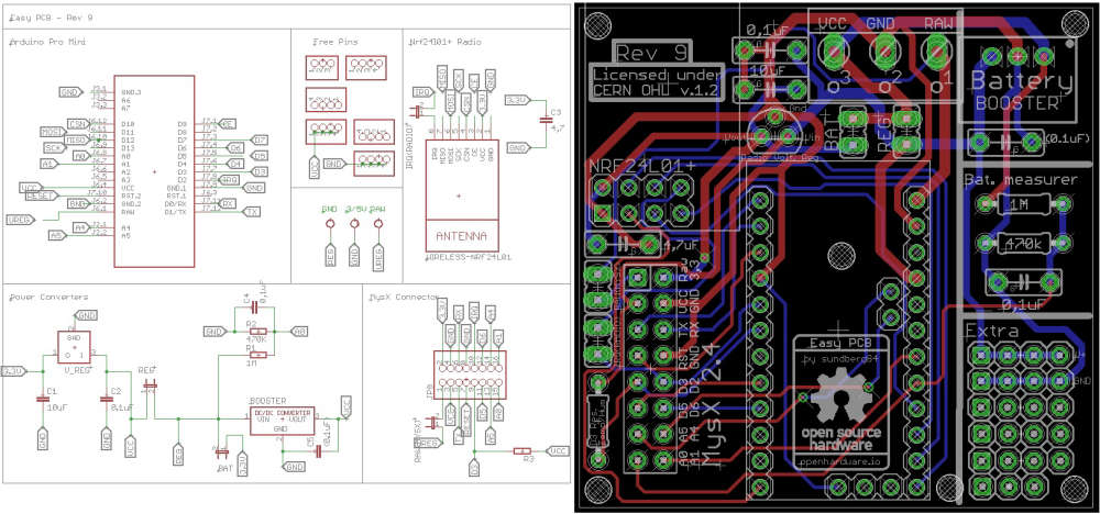
    This is Rev 9, Nrf24l01+

    0_1546847202029_Rev9 Schem.jpg

    @mfalkvidd - the rev tab in openhardware is the revision for the manufacturer. This doesnt match, because it starts at 0 and ticks up. If you have a board with rev 1 but make a small change without updating the revision number but still wants to upgrade it to the pcb manufacturer you need a new revision for them... so thats causes the confusion. But i think @hek named it M.Rev (Manufacturer revision) to try to keep them apart.


  • Sorry to bother you again (3rd time), still waiting for readable PDF of Rev. 9 schematic and board layout. Thank you


  • Hardware Contributor

    @apl2017 - why pdf? The image above is just as good? It wont present any other info?
    The reason why I ask is that I dont have eagles installed anymore... so its a bit of hassle for me.


  • sundberg84 Don't bother, I went through the hassle, downloaded Eagle and created readable PDF


  • @apl2017 care to share? 🙂


  • Hey, @sundberg84 , I am trying to order the rfm69 version from ITEAD and their M.Rev1 file I downloaded looks to be your v9. Can you upload the v10 to them so I may place an order?


  • Hello, i have built my first sensor based on your PCB. I am of course in learning mode so it refuses to work so far. it is motion detector. I suspect a problem on the radio nrf24 but does not know how to monitor the node with Arduino IDE serial monitor. If i connect the board to the USB the radio is not powered (built the node on battery). and if i connect the battery i have no access to serial monitor. I am afraid to connect both the USB and the batteries and burn the all thing...
    so far i know radio receives power/ PIR receives 3.3 Volts (have configured the PIR to 3.3)/ arduino mini pro led comes on with battery connected.
    Any advice would be really welcome.


  • The radio is only powered by the battery, the battery must be connected to test. Connect both the usb (set to 3.3v) and the battery, no damage will be caused by this.


  • Thanks Stephen. connected both and i can now see what is going on 🙂


  • Hardware Contributor

    @ElCheekytico - I dont know why they wont update to rev 10. I have uploaded the new revision to openhardware... nothing else I can do, sorry.


  • Hardware Contributor

    @pierre1410 - I would suggest you connect the battery, and then the usb/ftdi cable, but only GND, TX and RX fro the usb connection. This will have the node running on the batteries VCC and get you closer to the real deal. Using VCC from the usb adapter might be higher VCC than the batteries, and in worst case scenario it works great with that connected but not when you deploy and only use battery power.


  • @sundberg84 that is exactly what i experienced. thanks for the tip. struggling in fact to have my PIR sensor running on 3.3V. when i connect to the pin on the right of the board (3rd from top).. Arduino IDE serial terminal does not outcome any coherent information.


  • Hardware Contributor

    @pierre1410 ok - well not to get your hopes down but a motion detector on batteries are one of the harder builds. If you are using a booster with the batteries it's harder due to false triggers from the booster noice. Also I believe the quality of your motion detector module determine if it's possible..I've had detectors running fine on 3.3v but several which didn't.


  • Hello, Is there a way to solder a DC-DC booster 3.3V to 5V directly onto the Easy PCB or should it be connected separately to power a PIR for instance? and would that really prevent using 2xAA batteries to power the all thing? have tried to step down the PIR to work at 3.3V but it was not conclusive. Thanks a lot.


  • Hardware Contributor

    @pierre1410 - you can always use the prototyping area for a 3.3 to 5v booster but... booster + PIR might cause false triggers, so choose your booster wisely.


  • @sundberg84, had to migrate my gateway to Ethernet in the meantime but now I am on the PIR/ battery case. i have my booster to 5V in.. will post the results of it...


  • Mod

    @pierre1410 why do you need 5v? There are pir sensors working at 3v and you can even modify the standard pir sensor to work at 3v


  • Hello

    I think there is a mistake in your code (on github) to mesure battery.
    The array have 4 values, but you divide by 3. So you get to high result.
    https://github.com/sundberg84/HomeAutomation/blob/master/BatteryMeasurer/BatteryMeasurer.ino
    On line 77

    Everything else is ok in my case 🙂 the board works well with 2 battery AA, and 47uF cap (not with 4.7uF) .


  • Mod

    Nice catch @barrydou

    The bat array is declared to hold 3 elements

    int batArray[3];
    

    but then 4 values are fetched

    batteryPcnt = (batArray[0] + batArray[1] + batArray[2] + batArray[3]);
    

    batArray[3] is outside of the array, so the ram here could hold any value.

    The code should probably be changed to this

    batteryPcnt = (batArray[0] + batArray[1] + batArray[2]);


  • @mfalkvidd : I think you have to change the condition in if too :

    if (batLoop > 1) {
    

    With that, batLoop = 2 when entering in the if (so the 3 values of the array are filled : 0, 1, 2), calculating the average and reseting the batLoop to 0.
    If not modify, the array will be set with batArray[3] just before entering the

    if (batLoop > 2) {
    

    Other way is to set the batArray size to 4 values, and divide by 4 (I'm actually trying that).


  • Hardware Contributor

    @barrydou @mfalkvidd - thanks.
    Wouldnt it be easiest to just "+ batArray[3]" so it is

    batteryPcnt = (batArray[0] + batArray[1] + batArray[2]
    

    the declaration = 3 elements
    batterypct = 3 elements
    batloop > 2 should be correct (0,1 and 2)

    I dont think the code has made any faulty readings since the declaration is only for 3 elements, making batArray[3] never used? (Or always been 0). The batteryPcnt is then divived by 3.


  • Mod

    @sundberg84 batloop > 2 is incorrect, since that means batloop==3 and the code above has just written outside the array, corrupting whatever happened to be there.


  • Hardware Contributor

    We must be ordering EasyPCB alof from PCBway since they used it as an example board for this youtuber:

    PCBWay Circuit Boards - 2 Minute Review📦🛠🔎 – 02:57
    — MKme Lab


  • Hardware Contributor

    @sundberg84 haha gorgeous, I think they only sent open hardware boards, and ran some batches from boards available on openhardware, as except the perfboards they send as free gifts the other real PCBs are MySWeMosIRShield by @emc2 and the RollerShutterNode by @Scalz

    https://www.openhardware.io/view/385/MySWeMosIRShield-IR-blaster-shield-for-WeMos-D1
    https://www.openhardware.io/view/22/Roller-Shutter-Node


  • Hardware Contributor

    Looks nice in red 😉


  • hello, i have a stupid question... on the 3 rows below VCC and GD on your prototyping area; are the rows connected horizontally like a breadboard? thanks


  • Hardware Contributor

    @pierre1410 - no stupid questions, simple answer though, no 🙂

    0_1552248309070_ca19349e-433c-4891-99bc-739fc3c19668-image.png


  • Hello Sundberg84 et al,
    I purchased Easy Newbie PCB (Rev 10) with the hope of jumping into the IoT rave... I tried to create the Gateway - and it works perfectly. I also found and created an advanced Water Sprinkler MyS project by Pete and Co!... that also worked perfectly.

    However, I cant seem to get simpler beginner sketches to work with EasyNewbie. I have soldered the need components (the regulated version). I plan to connect to a 4 relay module, but for now, I am simulating the relay with a simple LED attached to D2. I have uploaded the following sketch which was originally written for version 1.0 MySensors - but have been corrected using guidelines I found for converting 1.0 - 2.0 version. but still no cheese - the controller (Domoticz) displays the Node, but not the complete child nodes, - the LED connected to pin D2 (or D3, D5..) on the Easy Newbie doesn't light up even when I toggle the switches and devices on controller. Don't know what I might be doing wrong, please help.

    // Example sketch showing how to control physical relays. 
    // This example will remember relay state even after power failure.
    
    // Enable debug prints
    #define MY_DEBUG
    
    // Enable and select radio type attached
    #define MY_RADIO_NRF24
    
    #define MY_NODE_ID 4  // Set this to fix your Radio ID or use AUTO or 1
    #define MY_REGISTRATION_FEATURE // Forece registration
    #define MY_REGISTRATION_RETRIES 5
    
    #include <Wire.h>
    #include <TimeLib.h>
    #include <SPI.h>
    #include <MySensors.h>
    #include <LCD.h>
    #include <LiquidCrystal.h>
    #include <LiquidCrystal_I2C.h>
    
    // For Debug
    #ifdef DEBUG_ON
    #define DEBUG_PRINT(x)   Serial.print(x)
    #define DEBUG_PRINTLN(x) Serial.println(x)
    #else
    #define DEBUG_PRINT(x)
    #define DEBUG_PRINTLN(x)
    #define SERIAL_START(x)
    #endif
    
    //#define RELAY_1  2  // Arduino Digital I/O pin number for first relay (second on pin+1 etc)
    #define RELAY_PIN 3
    #define NUMBER_OF_RELAYS 4 // Total number of attached relays
    #define RELAY_ON 0  // GPIO value to write to turn on attached relay
    #define RELAY_OFF 1 // GPIO value to write to turn off attached relay
    #define SKETCH_NAME "Base Relay Node"
    #define SKETCH_VERSION "0.1.2"
    #define CHILD_ID 0
    
    MyMessage msg(1,V_LIGHT);
    
    //void before()
    void setup()
    {
    
      for (int sensor=1, pin=RELAY_PIN; sensor<=NUMBER_OF_RELAYS; sensor++, pin++) {
        // Then set relay pins in output mode
        pinMode(pin, OUTPUT);
        // Set relay to last known state (using eeprom storage)
        digitalWrite(pin, loadState(sensor)?RELAY_ON:RELAY_OFF);
      }
    }
    
    void presentation() { 
      sendSketchInfo(SKETCH_NAME, SKETCH_VERSION);
    
      // Fetch relay status
      for (int sensor=1, pin=RELAY_PIN; sensor<=NUMBER_OF_RELAYS; sensor++, pin++) {
        // Register all sensors to gw (they will be created as child devices)
        //    present(sensor, S_BINARY);
        present(sensor, S_LIGHT);
     
        // Then set relay pins in output mode
        pinMode(pin, OUTPUT);   
        // Set relay to last known state (using eeprom storage) 
        boolean savedState = loadState(sensor);
        digitalWrite(pin, savedState?RELAY_ON:RELAY_OFF);
        send(msg.set(savedState? 1 : 0));
      }
          DEBUG_PRINTLN(F("Sensor Presentation Complete"));
    }
    void loop() 
    {
      // Alway process incoming messages whenever possible
      // Sleep until interrupt comes in on motion sensor. Send update every two minute.
    //  sleep(digitalPinToInterrupt(DIGITAL_INPUT_SENSOR), CHANGE, SLEEP_TIME);
    
    //      update Relays;
      for (int sensor=1, pin=RELAY_PIN; sensor<=NUMBER_OF_RELAYS; sensor++, pin++) {
        // Register all sensors to gw (they will be created as child devices)
        //    present(sensor, S_BINARY);
    send(msg.set(sensor).set(false), false);
    wait(50);
    
    }
    }
    void incomingMessage(const MyMessage &message)
    {
      // We only expect one type of message from controller. But we better check anyway.
      if (msg.type==V_STATUS) {
        // Change relay state
        digitalWrite(msg.sensor-1+RELAY_PIN, msg.getBool()?RELAY_ON:RELAY_OFF);
        // Store state in eeprom
        saveState(msg.sensor, msg.getBool());
        // Write some debug info
        Serial.print("Incoming change for sensor:");
        Serial.print(msg.sensor);
        Serial.print(", New status: ");
        Serial.println(msg.getBool());
      }  
    }
    

  • Hardware Contributor

    @eme - hi!
    Im very sorry, code is not my strong side.
    Do you think its a problem with the hardware?
    Do you have any logs?


  • @sundberg84 I have the Domoticz log below. but just incase it doesn't reveal much, do you have a working sketch for EasyNewbie and a 4-relay module block?

    2019-04-05 22:28:20.172 (My Sensors Gateway) Light/Switch (Light) 
    2019-04-05 22:28:21.229 (My Sensors Gateway) Light/Switch (Light) 
    2019-04-05 22:28:22.169 (My Sensors Gateway) Light/Switch (Light) 
    2019-04-05 22:28:55.333 Status: MySensors: Node: 3, Sketch Name: Base Relay Node 
    2019-04-05 22:28:56.459 (My Sensors Gateway) Light/Switch (Light) 
    2019-04-05 22:29:00.141 Status: LUA: All based event fired 
    2019-04-05 22:29:53.736 Status: User: Eme initiated a switch command (29/Light/On) 
    2019-04-05 22:29:54.297 (My Sensors Gateway) Light/Switch (Light) 
    2019-04-05 22:29:57.701 Status: User: Eme initiated a switch command (29/Light/Off) 
    2019-04-05 22:29:58.206 (My Sensors Gateway) Light/Switch (Light) 
    2019-04-05 22:30:00.533 Status: User: Eme initiated a switch command (28/Light/On) 
    2019-04-05 22:30:00.534 Status: LUA: All based event fired 
    2019-04-05 22:30:01.729 (My Sensors Gateway) Light/Switch (Light) 
    2019-04-05 22:30:07.427 (My Sensors Gateway) Light/Switch (Light) 
    2019-04-05 22:30:07.095 Status: User: Eme initiated a switch command (27/Light/On) 
    2019-04-05 22:30:13.674 Status: User: Eme initiated a switch command (29/Light/On) 
    2019-04-05 22:30:15.706 (My Sensors Gateway) Light/Switch (Light) 
    2019-04-05 22:30:19.773 Status: User: Eme initiated a switch command (26/Light/On) 
    2019-04-05 22:30:20.138 (My Sensors Gateway) Light/Switch (Light) 
    2019-04-05 22:30:55.858 (My Sensors Gateway) Light/Switch (Light) 
    2019-04-05 22:30:55.427 Status: User: Eme initiated a switch command (26/Light/Off) 
    2019-04-05 22:30:59.611 (My Sensors Gateway) Light/Switch (Light) 
    2019-04-05 22:30:59.256 Status: User: Eme initiated a switch command (29/Light/Off) 
    2019-04-05 22:31:00.280 Status: LUA: All based event fired 
    2019-04-05 22:31:02.813 Status: User: Eme initiated a switch command (27/Light/Off) 
    2019-04-05 22:31:03.242 (My Sensors Gateway) Light/Switch (Light) 
    2019-04-05 22:31:06.944 Status: User: Eme initiated a switch command (28/Light/Off) 
    2019-04-05 22:31:07.393 (My Sensors Gateway) Light/Switch (Light) 
    2019-04-05 22:31:22.892 (My Sensors Gateway) Light/Switch (Light) 
    2019-04-05 22:31:22.527 Status: User: Eme initiated a switch command (26/Light/On) 
    2019-04-05 22:32:00.351 Status: LUA: All based event fired ```

  • Hardware Contributor

    @eme sorry I don't. The most common "issue" is that power is to weak for 4 relays or noice is introduced in the radio from the relay.

    It's very hard to understand without real logs. Sorry


  • I eventually got it to work. I am not using the EasyNewbie to power the load (its for 24volts swimming pool light). Couldn't get the 4th relay to work - not sure why its not responding to the controller. but I noticed some bug with my batch of 16 PCB -

    Okay I think I have seen some bugs... my batch of EasyNewbie Rev 10 has some hardware issues - The provisions to attach sensors are not correctly marked. D6 doesn't actually connect to D6 pin on the Arduino (must have failed a via somewhere). I am not sure how many pins are used for the radio and other components, but if you intend to use this for a small project, I will avoid D8 - D13 as they appears to be taken. D1 and D2 are used for the TX & RX so you only have D2 - D6 to play with (more than enough pins for a newbie if you ask me).


  • Hardware Contributor

    @eme good you found the issue. First time I ever hear of a comfirmed PCB hardware bug, so its very rare. Very strange the silkscreen were moved or not aligned correctly as well. From where did you order the PCB?

    The documentation states which pins connect to what on the PCB, so make sure you check that out. D9-D13 are used by the radio as in all MySensors projects. D8 for the extra flash. You can find the MysX documentation here as well if you need to find out more about the pins.

    0_1555048586371_c862da60-5ecd-488a-93d4-87e755916846-image.png


  • @Sunberg84 I bought them off Ebay via this very site... The Packing List reads Shipped by Abdera's Sundberg Ostra Gransgatan 2, Lonsboda, Sverige 28070, SE. I believe that's you.
    Well I am forced to solder directly to the Nano pins, and so far so good. I think you should help with a 4 relay sketch that works. My appears to be a hit and run, works in the morning and fails after a while. but I am learning as I go.


  • Hardware Contributor

    @eme Thats me - ok, good to know then - but I guess you mean the Mini pins and not Nano since the PCB doesnt support the Nano?


  • @sundberg84 Yes you are right I meant to say ProMini not Nano - I have 18 of these PCB - not so happy I have to solder directly to the Arduino - that's exactly what I was avoiding in the first place. Do you have a good relay block sketch that works? Much appreciated if you can help.

    One last thing, I am trying to run a node off a 12Volts battery, can you explain this image below again?

    • Will this work for a 5V Promini?
    • What are the blue lines? and
    • what are the red lines?

    0_1555369081866_EasyPCBimage.png


  • Hardware Contributor

    @eme - its is very strange - I have a big batch here with Rev 10 and i checked atleast 20 of them randomly and all have continutiy between D6/pro mini and D6/MysX. You must have had extreme bad luck and if you check the others it should be ok.

    Can you post a picture (close up) of the board not working please showing D6/Pro mini and D6/MysX.

    For 12v I would use the prototyping area with a 12 > 5v converter. If you want to use the internal voltage regulator on the pro mini you can connect to RAW but beware that clones will not handle this very good. The specs are 12v but I have seen many bad clones getting destroyed.

    I dont really remember this image and from which context this is from. I guess the lines represent different voltages. Adding 12V on reg and a 12>5v regulator on the TO92 footprint will convert and feed the board 5v, but kill the radio...


  • I just checked my batch of Rev 10, random check of the batch checked out OK. I have 20 boards.


  • Dear sundberg84, thanks to your really nice and easy mysensors PCB. I ordered ten of them via SEEED and they were delivered today (REV.10). Unfortunally I found some serious bugs in the PCB design regarding the SPI Flash: First pin 6 (SPI SCK) of the flash chip is not connected at all - should be digital IO pin 13 of the Arduino pro mini. Second mistake: the filter capacitor of the flash chip is not between VCC and GND. Third mistake: pin 3 and pin 7 should be connected to VCC and not to the filter capacitor. I changed that on my arrived boards and the flash chip is now working perfectly. Kind regards, JPM


  • I checked the schematic, and:
    First mistake: Seems that the schematic is OK, the label for SCK (pin 6) is connected to physical pin 16 which is PCINT13 on the Arduino,
    Second mistake: that is a bug, filter capacitor is not connected correctly.
    Third mistake: That is also a bug, pin 7 and 3 should be connected to VCC
    Now I am going to check the PCB, be back shortly,


  • I have now checked the PCB, and you are right @JPM
    Pin 6 of the flash chip is not connected at all. No wonder I could not get that to work. Strangely is that the schematic is OK.
    Thanks for finding this, I will modify my boards to get them working.


  • Hardware Contributor

    Sorry for this. The flash has been untested by me. I will fix this asap and upload new files.

    The schematics is wrong:

    0_1556740599909_fa86bb19-0e0e-4d42-914a-1a5cd4214135-image.png

    New schematics:

    0_1556740825229_fd5b8945-a250-4d1f-b6e5-041a192190e0-image.png

    The same error goes for RFM version 😞


  • @mickecarlsson I found this out and wrote it above that D6 is not connected at all... but it was promptly swept aside cos nobody had reported it before now. I am glad someone else saw it, and that you had the notion to check. D4 is also not connected to the test area. I have been connecting directly to the Nano.


  • Hardware Contributor

    @eme im sorry - since your wrote "The provisions to attach sensors are not correctly marked. D6 doesn't actually connect to D6 pin on the Arduino" I thought you was talking about the MysX connector and not flash. If you mentioned flash I would probably found the issue. They are not talking about D6 but pin 6 on flash which connects to D13 on the Arduino.

    Are you sure it's the same problem? Not much that sounds the same.


  • @sundberg84 if you look at the schematic you have connected MySX pin 10 to D2, but according to the spec for the MySX 2.4 it should go to D4.


  • Hardware Contributor

    @mickecarlsson - I understand your point, and I have changed this back and forth and also asked @Anticimex becuase its a but unclear in the documentation.

    0_1557383122415_e66b877a-1c97-4672-b38e-b6f879788b68-image.png

    MysX 9 + 10 should go to a Digital IO with interrupt, and D2 and D3 is the only pins with interrupts on mini.

    I guess you are refering to Mysx_D3_INT but this is the MysX name.


  • Contest Winner

    @sundberg84 @mickecarlsson
    It is important to remember that MYSX is agnostic from any devices.
    Any names in MYSX pins bear no correlation to any device specific pin naming, so D3 and D4 mentioned on pin 9 and 10 has nothing to to with any D3 or D4 on any MCU.
    If you look here, you will find that the 'A' and 'D' notation is simply an indicator of the pin function (analog or digital) and it simply increments with the pin number, so the lowest analog or digital pin number in the MYSX connector will start at '1' and then increment as the pin number increments with '2' for the next digital being on pin '6'.
    Also note that since some pins are deprecated in MYSX 2.x, MYSX 2.x analog pins starts with 'A3'.


  • I was wondering if there are any CAD files for corner through hole size/locations for Rev 10? Trying to design enclosure for it.


  • @birinderk SHould be easy enough to measure it with a caliper. That's what I did with the earlier revisions of the board (rev 8 & 9). They had pretty much the same hole spacing. Here are a few of the enclosures/sensor cases that I did that fit the rev 8 and 9's.
    https://www.thingiverse.com/thing:2186286
    https://www.thingiverse.com/thing:3339158
    https://www.thingiverse.com/thing:2904969


  • Hardware Contributor


  • Does anyone know where we can find the write ups for old revisions? i have a bunch of Rev9 boards that, now that i have restarted these projects after a year break i cant remember the write ups for them....


  • Mod

    @markjgabb do you mean the stuff in README.md in the zip file that can be downloaded on the revisions tab?


  • @mfalkvidd yeh i guess so, not quite what i was after the orignal in that version had some good pictures and such of what went where on the board....do doubt i can work it out from an old dead one i have lying around, was just hoping for a nice visual guide to get me back into it.


  • Mod

    @markjgabb not sure if this is what you want, but if I paste the contents of the readme into a markdown viewer (for example https://dillinger.io/ ) I get the images:
    0_1564395113017_4c0c99a3-6b36-41c9-981b-74a034f26670-image.png


Suggested Topics

  • 14
  • 6
  • 2
  • 1
  • 2
  • 14
  • 2
  • 15

0
Online

11.2k
Users

11.1k
Topics

112.5k
Posts