💬 Easy/Newbie PCB for MySensors
-
Hi! @chuckconnors
You should input power/gnd to the 5v/GND on the PCB and not the ftdi connector on the arduino you have soldered on the pcb. See the images above. This is how the board is designed. It doesnt matter if its 3.3 or 5v.
The resistor is for if you want to use for example a dallas temp or dht22 on pin 3, then you can add a resistor there since these sensors require this.@sundberg84 Thanks for the reply. Please forgive my ignorance, but can you explain what happens if you connect power via the FTDI pins? Wouldn't it still power the chip and radio?
Should I supply the 5V/GND from the FTDI interface to the VCC/GND pads on the bottom left side of the board?
-
@chuckconnors well it depends on your setup. It can be done with powering through fdti but it's easier to just not recommend it. For example 3.3v with a booster /bat setup powering through vcc on arduino will not power the radio.
That works great. You can connect the fdti to the arduino but extend vcc and gnd with wired to the pcb. To power everything run these cables to the pads in the middle and top of the pcb.
-
@sundberg84 Thanks for the clarification. I took a look at the board images and I see what you mean. Forgive me again for trying your patience, but could you be so kind as to tell me what the minimum required components are for using this board with a 3.3V Arduino?
Currently I'm only using the Arduino, radio, radio capacitor, power supply (battery or 5V ), and whatever sensors required for that node. This worked out well using the standard hookups as the radio was being powered by the Arduino and the radio is guaranteed the correct voltage via the built in regular on the Arduino, but as you've mentioned this isn't an option with your board. Do I need to include the battery caps and regulator? Again, I'm a novice and I can follow the traces on the top side of the board using the silkscreen labels as a guide but it's a bit harder to follow on the unlabeled bottom side. Do most of you guys use the 5V Arduino?
-
If you use the FTDI connector, make sure its the 3.3v and connect it to Gnd/Pwr on the PCB and not Arduino FDTI connector.
You could just exclude those pins and connect a battery directly and use that as power and the FDTI as programmer/serial debug onlyBat or Reg is nessecary!
See this picture for battery use: https://www.openhardware.io/view/4/EasyNewbie-PCB-for-MySensors
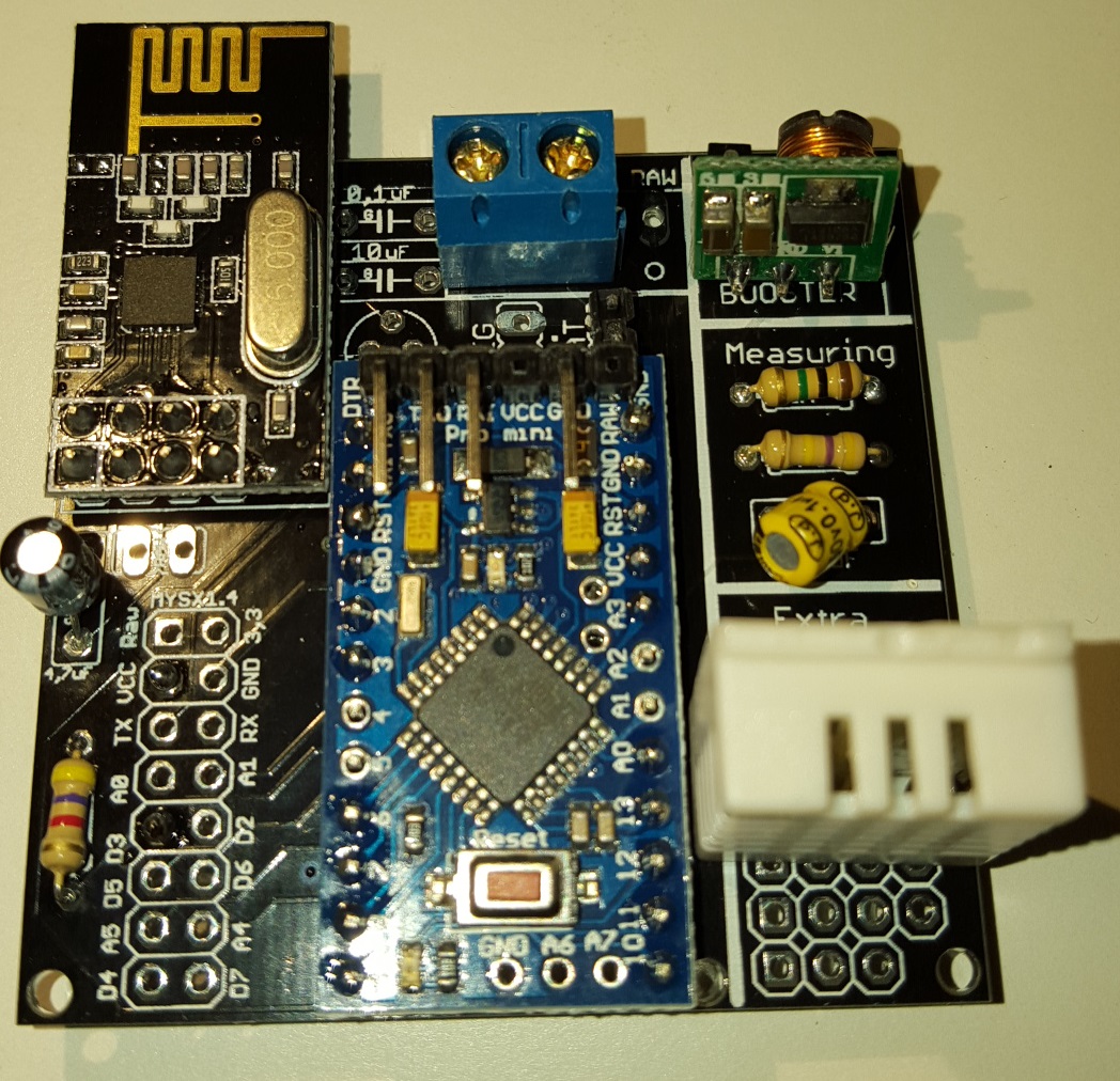
https://www.openhardware.io/uploads/568ed84b60aa3f8965fbf095/image/3.jpg
All components in the image is needed (except battery measurment).
If you dont want to use booster you need to bypass that one with a wire/jumper (or set the jumper on REG instead of BAT but that kills the logic).The battery doesnt "need" the 0,1uF but see here:https://www.mysensors.org/build/battery
"The tap point could be bypassed with a 0.1 uF capacitor to keep the noise level low, at this otherwise high impedance point. "@sundberg84 said:
If you use the FTDI connector, make sure its the 3.3v and connect it to Gnd/Pwr on the PCB and not Arduino FDTI connector.
You could just exclude those pins and connect a battery directly and use that as power and the FDTI as programmer/serial debug onlyBat or Reg is nessecary!
See this picture for battery use: https://www.openhardware.io/view/4/EasyNewbie-PCB-for-MySensors
https://www.openhardware.io/uploads/568ed84b60aa3f8965fbf095/image/3.jpg
All components in the image is needed (except battery measurment).
If you dont want to use booster you need to bypass that one with a wire/jumper (or set the jumper on REG instead of BAT but that kills the logic).The battery doesnt "need" the 0,1uF but see here:https://www.mysensors.org/build/battery
"The tap point could be bypassed with a 0.1 uF capacitor to keep the noise level low, at this otherwise high impedance point. " -
@chuckconnors Well, it is possible... you can always hard wire/bypass stuff with wires... its possible.
See @BastienVH for minimun req. 3.3v. In bat. operations you feed the radio directly from batteries - less noice and radio can handle down to 0.9V (i think) so its not a problem. You need the booster for sensors and arduino requiers 3.3v to run. You can also feed 3.3v directly to VCC on the PCB if you have that regulated. Then you can just add jumper to reg.If you tell me exactly what you want to do i can help you and explain what you need and how to wire it. With your setup now like you described and you run that on 3v batteries it will be dead within a week.
If you want battery power - you should go with 3.3v arduino (advantage: last longer)
If you have regulated 5v (like from a phone charger) use 5v arduino (advantage: smaller PCB) -
First battery node with rev 8 is up and running... need to test 5v version as well but looks good so far
-
Hi,
I've received boards from dirtypcb, it looks pretty good! Very nice design!Just have a few questions:
- May I use 78L33 voltage regulator instead of LE33ACZ?
- Do you know what is the RAW input tollerance of Pro Mini 3.3V (ebay one, not genuine one)?
I'm thinking of attach temperature sensor to my PIRs in my home and feed it parasitically from PIR (~13VDC). Do you think is it possible?
-
Hi Lukasz!
-
78L33 is a 3.3v regulator so yes, but is different pins depending on which version you have so you need to check where you put the pins. From left Vout, Gnd and Vin should be connected to the PCB. Compare it with LE33 pinouts.
-
In theory it should be 12v BUT its a fact that manu clones cant handle that. I would not go above 9v.
-
-
Hi Lukasz!
-
78L33 is a 3.3v regulator so yes, but is different pins depending on which version you have so you need to check where you put the pins. From left Vout, Gnd and Vin should be connected to the PCB. Compare it with LE33 pinouts.
-
In theory it should be 12v BUT its a fact that manu clones cant handle that. I would not go above 9v.
- Ok I will check pinouts
- I understand. So what is the best way in your opinion to feed node parasitically in safe manner? Use voltage regulator to step down voltage to safe 3.3v? Should I expect any significant heat? I'm aware of heat becouse it can trigger false alarm of my PIR
-
-
I would go with a voltage regulator from your 13v to 5 or 3.3v depending on which arduino you buy. I would connect this to PWR on the pcb and avoid using arduino internal voltage regulator (avoid use of two voltage regulators).
-
Thanks sundberg84, I will give a try.
One last question. I didn't find any note in BOM list. May I use ceramic caps instead of electrolitic ones?
I 'm not able to find electrolitic 0.1uF caps at my local store. -
Yes, you can replace it with a ceramic. There are alot to read about the differences on the net.
-
@Dombo71 - Hi!
The BOM is complete, all capacitors needed and its values are found in the BOM tab.
Since caps are so cheap and common i wont specify any link since you can find theme anywhere. -
Anyone from the Netherlands who ordered a pack of the rev.8 boards? How long did it take to be delivered?
The status update on dirtypcbs.com saysShipped on 27 Jan 2016and I can't wait until I receive them! :) -
Anyone from the Netherlands who ordered a pack of the rev.8 boards? How long did it take to be delivered?
The status update on dirtypcbs.com saysShipped on 27 Jan 2016and I can't wait until I receive them! :) -
Anyone from the Netherlands who ordered a pack of the rev.8 boards? How long did it take to be delivered?
The status update on dirtypcbs.com saysShipped on 27 Jan 2016and I can't wait until I receive them! :)@lxz Chinese New Year Holiday is just over, there seems to be quite a backlog for items ordered in january. It depends on some luck, to Antwerpen took around 6 weeks.
-
I love this PCB. It makes things so much easier. I am having a little problem with the battery version though. I think I've got it wired up right. I've got the jumper. I've got the booster. But, when I plug in a battery (I've tried a 3.7 volt battery, outputting 3.3v - the one from the solar weather station project, and 2 or 4 AA batteries), I get a "Radio Init Fail" message in the serial monitor. Also, the LED at the back, the one near the reset button, does not light brightly. It initially flashes brightly, then nothing.
I've wired it up two different times for the battery setup, and with neither am I getting the live radio.
I am able to get a good radio with the 5v setup.