💬 Easy/Newbie PCB for MySensors
-
@mickecarlsson - I understand your point, and I have changed this back and forth and also asked @Anticimex becuase its a but unclear in the documentation.
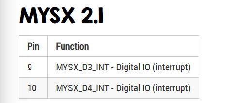
MysX 9 + 10 should go to a Digital IO with interrupt, and D2 and D3 is the only pins with interrupts on mini.
I guess you are refering to Mysx_D3_INT but this is the MysX name.
@sundberg84 @mickecarlsson
It is important to remember that MYSX is agnostic from any devices.
Any names in MYSX pins bear no correlation to any device specific pin naming, so D3 and D4 mentioned on pin 9 and 10 has nothing to to with any D3 or D4 on any MCU.
If you look here, you will find that the 'A' and 'D' notation is simply an indicator of the pin function (analog or digital) and it simply increments with the pin number, so the lowest analog or digital pin number in the MYSX connector will start at '1' and then increment as the pin number increments with '2' for the next digital being on pin '6'.
Also note that since some pins are deprecated in MYSX 2.x, MYSX 2.x analog pins starts with 'A3'. -
I was wondering if there are any CAD files for corner through hole size/locations for Rev 10? Trying to design enclosure for it.
@birinderk SHould be easy enough to measure it with a caliper. That's what I did with the earlier revisions of the board (rev 8 & 9). They had pretty much the same hole spacing. Here are a few of the enclosures/sensor cases that I did that fit the rev 8 and 9's.
https://www.thingiverse.com/thing:2186286
https://www.thingiverse.com/thing:3339158
https://www.thingiverse.com/thing:2904969 -
I was wondering if there are any CAD files for corner through hole size/locations for Rev 10? Trying to design enclosure for it.
-
Does anyone know where we can find the write ups for old revisions? i have a bunch of Rev9 boards that, now that i have restarted these projects after a year break i cant remember the write ups for them....
-
@markjgabb do you mean the stuff in README.md in the zip file that can be downloaded on the revisions tab?
@mfalkvidd yeh i guess so, not quite what i was after the orignal in that version had some good pictures and such of what went where on the board....do doubt i can work it out from an old dead one i have lying around, was just hoping for a nice visual guide to get me back into it.
-
@mfalkvidd yeh i guess so, not quite what i was after the orignal in that version had some good pictures and such of what went where on the board....do doubt i can work it out from an old dead one i have lying around, was just hoping for a nice visual guide to get me back into it.
@markjgabb not sure if this is what you want, but if I paste the contents of the readme into a markdown viewer (for example https://dillinger.io/ ) I get the images:
-
@markjgabb not sure if this is what you want, but if I paste the contents of the readme into a markdown viewer (for example https://dillinger.io/ ) I get the images:
@mfalkvidd ahhhhh That answers my question perfectly....i was just dumping it into notepad ++ ill try that first thing in the morning.
-
Hi,
First of all: I really appreciate the simplicity and flexibility of this board!
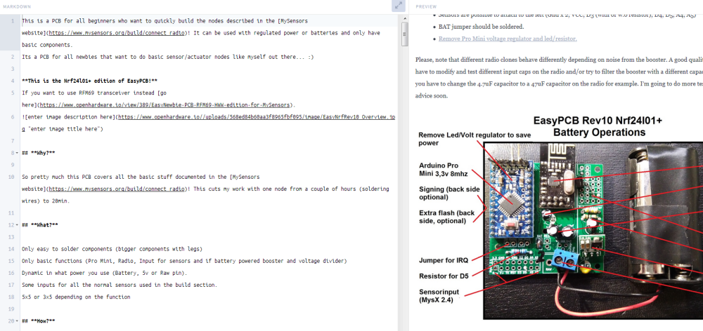
Now then, I have a problem with battery life which is only around 3 weeks for my DHT22 node and around 8 weeks for my BMP280 node. Both are 3.3V mini clones with NRF24 radios (probably clones) that run on 2xAAA batteries and a booster. I use NodeManager for software and report sensor values in 2 minute intervals. LED and voltage regulator has been desoldered from the Pro Mini.
Why isn't battery life better - am I missing anything obvious?
-
Can/should I remove C2 (10uF) and C3 (0.1uF) capacitors? I added them first but after checking the schematics I now think they are not used at all for the battery/booster setup?
-
What battery life can I expect for a BMP280 on 2xAAA batteries and booster?
-
New batteries report at 3.13V. When the nodes fail, reported battery voltage is around 2.6V. However, when measured I get it to around 1.6V (at no load). This could be a software problem but I include it as a clue. My setup in NodeManager is:
battery.setBatteryPin(0);
battery.setMinVoltage(1.8);
battery.setMaxVoltage(3.1);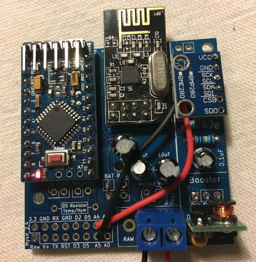
-
-
Hi,
First of all: I really appreciate the simplicity and flexibility of this board!
Now then, I have a problem with battery life which is only around 3 weeks for my DHT22 node and around 8 weeks for my BMP280 node. Both are 3.3V mini clones with NRF24 radios (probably clones) that run on 2xAAA batteries and a booster. I use NodeManager for software and report sensor values in 2 minute intervals. LED and voltage regulator has been desoldered from the Pro Mini.
Why isn't battery life better - am I missing anything obvious?
-
Can/should I remove C2 (10uF) and C3 (0.1uF) capacitors? I added them first but after checking the schematics I now think they are not used at all for the battery/booster setup?
-
What battery life can I expect for a BMP280 on 2xAAA batteries and booster?
-
New batteries report at 3.13V. When the nodes fail, reported battery voltage is around 2.6V. However, when measured I get it to around 1.6V (at no load). This could be a software problem but I include it as a clue. My setup in NodeManager is:
battery.setBatteryPin(0); battery.setMinVoltage(1.8); battery.setMaxVoltage(3.1);@fredswed - Hi!
You should be able to get much longer batterylife than this! I have same setup running around 12 months.It is hard to say, your setup in the image looks correct. Sometimes when i bought boosters or sensors they draw much more current than expected due to clones. In these cases I try to solder pro-mini and radio, then connect a multimeter in series with the batteries to analyze current consumption - then add sensor by sensor to find out what is drawing current - is this possible for you?
- The are used for the booster to smooth noice, so both can be used in your setup.
- 2xAA with DHT22 = 1 year, BMP280 has a low current consuption when sleeping so it should be able to do atleat 1 year there as well.
- I dont know nodemanager. The booster should boost the voltate for VCC, so it depends on the specs for your booster.
My first thought is that your BMP module is always active drawing alot of current even though you put the node to sleep. Test current consumption during sleep. Should be < 100uA and even maybe 50 uA atleast!
-
-
Hi,
First of all: I really appreciate the simplicity and flexibility of this board!
Now then, I have a problem with battery life which is only around 3 weeks for my DHT22 node and around 8 weeks for my BMP280 node. Both are 3.3V mini clones with NRF24 radios (probably clones) that run on 2xAAA batteries and a booster. I use NodeManager for software and report sensor values in 2 minute intervals. LED and voltage regulator has been desoldered from the Pro Mini.
Why isn't battery life better - am I missing anything obvious?
-
Can/should I remove C2 (10uF) and C3 (0.1uF) capacitors? I added them first but after checking the schematics I now think they are not used at all for the battery/booster setup?
-
What battery life can I expect for a BMP280 on 2xAAA batteries and booster?
-
New batteries report at 3.13V. When the nodes fail, reported battery voltage is around 2.6V. However, when measured I get it to around 1.6V (at no load). This could be a software problem but I include it as a clue. My setup in NodeManager is:
battery.setBatteryPin(0); battery.setMinVoltage(1.8); battery.setMaxVoltage(3.1);@fredswed hello, are you sure you booster is wired correctly and running fine ?
Node failing around 2.6V looks a lot like the value before the default brownout detection (2.7V). Then when you are at this level the node will be in a reset loop forever and completely drain the battery, but of course your node will not be able to report it.
So I would check the wiring and behavior of the boosters as they don't seem to do their jobs. I might be wrong but it would be a strange coincidence to have both nodes failing just at the brown out voltage.
-
-
Hi A question about powering using the step booster. When I connect the BAT jumper it would seem from the schematic that the output of the booster will be delivered to vcc (i.e. the arduino) but the supply to the radio module will be the battery supply. Is that what was intended?
-
Hi A question about powering using the step booster. When I connect the BAT jumper it would seem from the schematic that the output of the booster will be delivered to vcc (i.e. the arduino) but the supply to the radio module will be the battery supply. Is that what was intended?
-
Excited to get started with this board, ordered 10 and soldered up the basic components for a 3.3v battery-powered sensor last night. Got everything soldered exactly as in the battery operated picture for rev 10 on the newbie-pcb page with the exception of the D5 resistor.
When I connect the batteries to the PCB, the LED on the pro mini does not turn on, so I'm assuming it's not getting power. When I connect the battery to RAW, the LED on the pro mini turns on. Any ideas on where I should start troubleshooting before I start removing and replacing components?
I know the pro mini is good, I've uploaded a sketch to it using FTDI. I'm pretty sure my soldered connections are ok. I've double checked caps and resistors. I don't think I checked the step-up booster, so I'll try to test that to ensure it's functioning correctly, but any advice would be really appreciated!
@genuinejd - can you post a picture of your pcb? Might be easier.
If you have a multimeter, you can measure the input and output of the booster. -
@genuinejd - can you post a picture of your pcb? Might be easier.
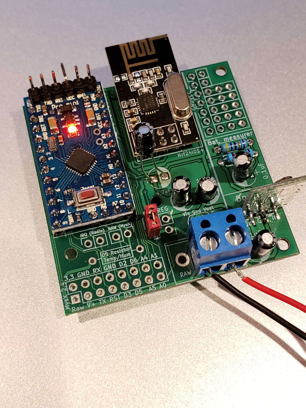
If you have a multimeter, you can measure the input and output of the booster.@sundberg84 I meant to post a picture, then last night I discovered my issue. I soldered all the components except the pro mini! Once I did that, everything started working. I did discover that mys was reporting "No potential parents replied to find parent request." Once I changed my radio cap from 4.7 to 47 it started sending messages immediately.
Here's my first node (I haven't removed components from the pro mini yet for extended battery life), with bare minimum components in all it's battery-powered newbie glory!
Thanks!
-
@sundberg84 I meant to post a picture, then last night I discovered my issue. I soldered all the components except the pro mini! Once I did that, everything started working. I did discover that mys was reporting "No potential parents replied to find parent request." Once I changed my radio cap from 4.7 to 47 it started sending messages immediately.
Here's my first node (I haven't removed components from the pro mini yet for extended battery life), with bare minimum components in all it's battery-powered newbie glory!
Thanks!
@genuinejd - Nice work! Thanks for reporting back! :)
-
@genuinejd - Nice work! Thanks for reporting back! :)
@sundberg84 So as it turns out, it worked great for about a day while I was letting it run to test battery life. Suddenly my gateway was not receiving any messages from my node.
- I checked all the caps, the booster, etc.
- I tried a few different caps for the radio up to 100uF
- The voltage on the radio matched the voltage from the battery.
- I tried switching to the REG jumper and wiring across the voltage regulator, the radio was then getting 3.3v from the booster, but still no communication between the node and gateway
- I also tried using my bench power supply for reg 3.3v.
Strangely, the ONLY thing that worked was when I used the 5v post on my bench power supply (with the BAT jumper, no voltage converter)
I have not yet tried swapping out the radio since it works with 5v, but I'm unsure what to try next. I have 6 other mys nodes communicating with my gateway with no problems and greater distances (all using nanos).
Any suggestions? Apologies if this doesn't sound like an issue with the board, I can post in the troubleshooting forum if you think it's a radio problem.
-
@sundberg84 So as it turns out, it worked great for about a day while I was letting it run to test battery life. Suddenly my gateway was not receiving any messages from my node.
- I checked all the caps, the booster, etc.
- I tried a few different caps for the radio up to 100uF
- The voltage on the radio matched the voltage from the battery.
- I tried switching to the REG jumper and wiring across the voltage regulator, the radio was then getting 3.3v from the booster, but still no communication between the node and gateway
- I also tried using my bench power supply for reg 3.3v.
Strangely, the ONLY thing that worked was when I used the 5v post on my bench power supply (with the BAT jumper, no voltage converter)
I have not yet tried swapping out the radio since it works with 5v, but I'm unsure what to try next. I have 6 other mys nodes communicating with my gateway with no problems and greater distances (all using nanos).
Any suggestions? Apologies if this doesn't sound like an issue with the board, I can post in the troubleshooting forum if you think it's a radio problem.
@genuinejd - the radio can not work with 5v, sorry but this might destroyed your radio. Do you have any serial debut for your node? Can you see what it does? It might be alot of different things, maybe the booster. In many times I have seen bad boosters which introduces noice and makes the radio go crasy.