Skip to content
  • OpenHardware.io
  • Categories
  • Recent
  • Tags
  • Popular
Skins
  • Light
  • Brite
  • Cerulean
  • Cosmo
  • Flatly
  • Journal
  • Litera
  • Lumen
  • Lux
  • Materia
  • Minty
  • Morph
  • Pulse
  • Sandstone
  • Simplex
  • Sketchy
  • Spacelab
  • United
  • Yeti
  • Zephyr
  • Dark
  • Cyborg
  • Darkly
  • Quartz
  • Slate
  • Solar
  • Superhero
  • Vapor

  • Default (No Skin)
  • No Skin
Collapse
Brand Logo
  1. Home
  2. OpenHardware.io
  3. 💬 Easy/Newbie PCB for MySensors
  • Getting Started
  • Controller
  • Build
  • Hardware
  • Download/API
  • Forum
  • Store

💬 Easy/Newbie PCB for MySensors

Scheduled Pinned Locked Moved OpenHardware.io
mysensorsbatteryeasynewbiepcbmysx
716 Posts 111 Posters 305.9k Views 93 Watching
  • Oldest to Newest
  • Newest to Oldest
  • Most Votes
Reply
  • Reply as topic
Log in to reply
This topic has been deleted. Only users with topic management privileges can see it.
  • sundberg84S Offline
    sundberg84S Offline
    sundberg84
    Hardware Contributor
    wrote on last edited by sundberg84
    #62

    @chuckconnors Well, it is possible... you can always hard wire/bypass stuff with wires... its possible.
    See @BastienVH for minimun req. 3.3v. In bat. operations you feed the radio directly from batteries - less noice and radio can handle down to 0.9V (i think) so its not a problem. You need the booster for sensors and arduino requiers 3.3v to run. You can also feed 3.3v directly to VCC on the PCB if you have that regulated. Then you can just add jumper to reg.

    If you tell me exactly what you want to do i can help you and explain what you need and how to wire it. With your setup now like you described and you run that on 3v batteries it will be dead within a week.

    If you want battery power - you should go with 3.3v arduino (advantage: last longer)
    If you have regulated 5v (like from a phone charger) use 5v arduino (advantage: smaller PCB)

    Controller: Proxmox VM - Home Assistant
    MySensors GW: Arduino Uno - W5100 Ethernet, Gw Shield Nrf24l01+ 2,4Ghz
    MySensors GW: Arduino Uno - Gw Shield RFM69, 433mhz
    RFLink GW - Arduino Mega + RFLink Shield, 433mhz

    C 1 Reply Last reply
    0
    • sundberg84S Offline
      sundberg84S Offline
      sundberg84
      Hardware Contributor
      wrote on last edited by
      #63

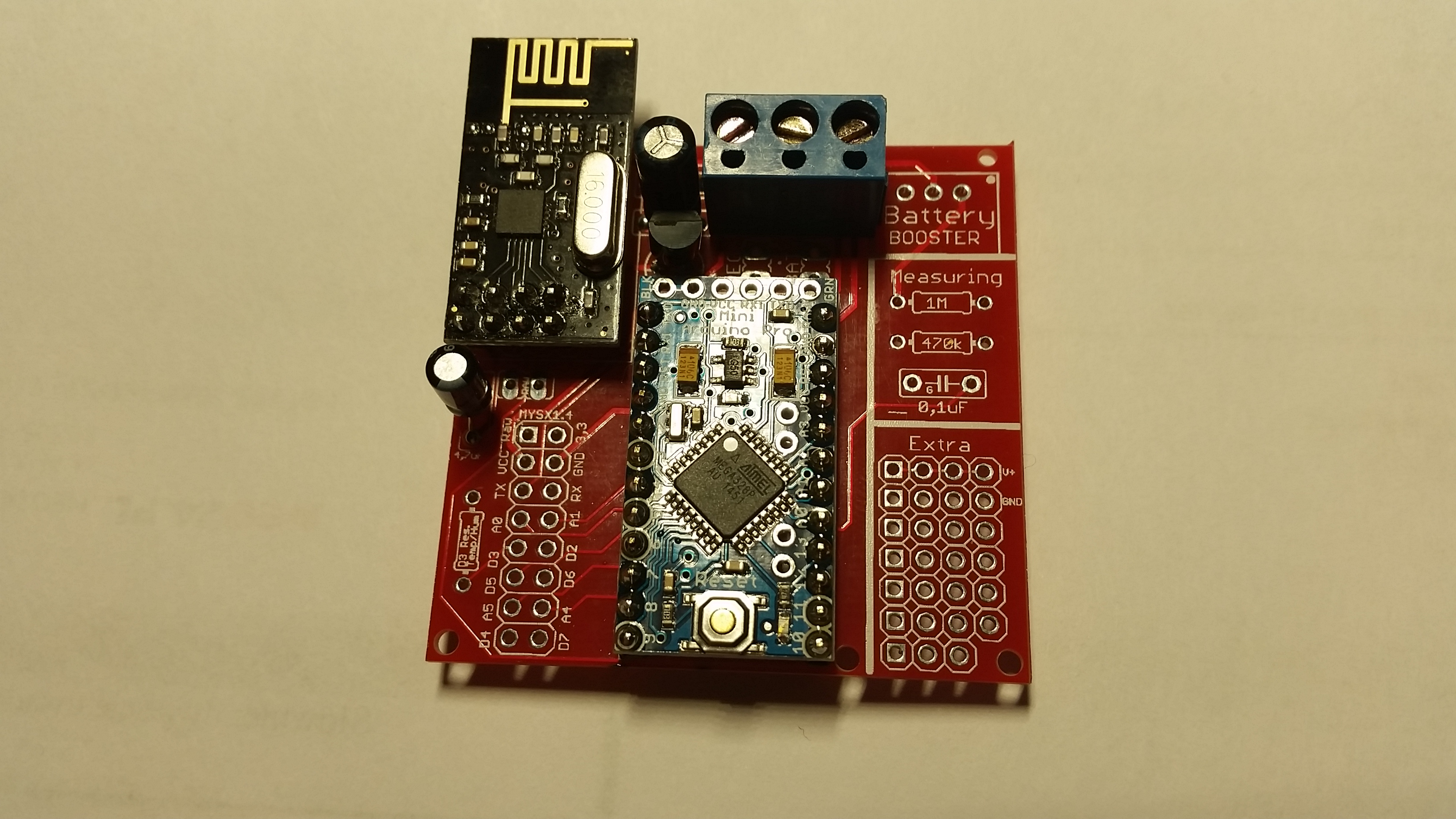
      First battery node with rev 8 is up and running... need to test 5v version as well but looks good so far
      0_1456177952831_20160222_213338.jpg

      Controller: Proxmox VM - Home Assistant
      MySensors GW: Arduino Uno - W5100 Ethernet, Gw Shield Nrf24l01+ 2,4Ghz
      MySensors GW: Arduino Uno - Gw Shield RFM69, 433mhz
      RFLink GW - Arduino Mega + RFLink Shield, 433mhz

      1 Reply Last reply
      3
      • Ɓ Offline
        Ɓ Offline
        Ɓukasz Rybak
        wrote on last edited by
        #64

        Hi,
        I've received boards from dirtypcb, it looks pretty good! Very nice design!

        Just have a few questions:

        1. May I use 78L33 voltage regulator instead of LE33ACZ?
        2. Do you know what is the RAW input tollerance of Pro Mini 3.3V (ebay one, not genuine one)?
          I'm thinking of attach temperature sensor to my PIRs in my home and feed it parasitically from PIR (~13VDC). Do you think is it possible?
        1 Reply Last reply
        0
        • sundberg84S Offline
          sundberg84S Offline
          sundberg84
          Hardware Contributor
          wrote on last edited by sundberg84
          #65

          Hi Lukasz!

          1. 78L33 is a 3.3v regulator so yes, but is different pins depending on which version you have so you need to check where you put the pins. From left Vout, Gnd and Vin should be connected to the PCB. Compare it with LE33 pinouts.

          2. In theory it should be 12v BUT its a fact that manu clones cant handle that. I would not go above 9v.

          Controller: Proxmox VM - Home Assistant
          MySensors GW: Arduino Uno - W5100 Ethernet, Gw Shield Nrf24l01+ 2,4Ghz
          MySensors GW: Arduino Uno - Gw Shield RFM69, 433mhz
          RFLink GW - Arduino Mega + RFLink Shield, 433mhz

          Ɓ 1 Reply Last reply
          0
          • sundberg84S sundberg84

            Hi Lukasz!

            1. 78L33 is a 3.3v regulator so yes, but is different pins depending on which version you have so you need to check where you put the pins. From left Vout, Gnd and Vin should be connected to the PCB. Compare it with LE33 pinouts.

            2. In theory it should be 12v BUT its a fact that manu clones cant handle that. I would not go above 9v.

            Ɓ Offline
            Ɓ Offline
            Ɓukasz Rybak
            wrote on last edited by
            #66

            @sundberg84

            1. Ok I will check pinouts
            2. I understand. So what is the best way in your opinion to feed node parasitically in safe manner? Use voltage regulator to step down voltage to safe 3.3v? Should I expect any significant heat? I'm aware of heat becouse it can trigger false alarm of my PIR
            1 Reply Last reply
            0
            • sundberg84S Offline
              sundberg84S Offline
              sundberg84
              Hardware Contributor
              wrote on last edited by
              #67

              I would go with a voltage regulator from your 13v to 5 or 3.3v depending on which arduino you buy. I would connect this to PWR on the pcb and avoid using arduino internal voltage regulator (avoid use of two voltage regulators).

              Controller: Proxmox VM - Home Assistant
              MySensors GW: Arduino Uno - W5100 Ethernet, Gw Shield Nrf24l01+ 2,4Ghz
              MySensors GW: Arduino Uno - Gw Shield RFM69, 433mhz
              RFLink GW - Arduino Mega + RFLink Shield, 433mhz

              1 Reply Last reply
              0
              • Ɓ Offline
                Ɓ Offline
                Ɓukasz Rybak
                wrote on last edited by
                #68

                Thanks sundberg84, I will give a try.
                One last question. I didn't find any note in BOM list. May I use ceramic caps instead of electrolitic ones?
                I 'm not able to find electrolitic 0.1uF caps at my local store.

                1 Reply Last reply
                0
                • sundberg84S Offline
                  sundberg84S Offline
                  sundberg84
                  Hardware Contributor
                  wrote on last edited by sundberg84
                  #69

                  Yes, you can replace it with a ceramic. There are alot to read about the differences on the net.

                  Controller: Proxmox VM - Home Assistant
                  MySensors GW: Arduino Uno - W5100 Ethernet, Gw Shield Nrf24l01+ 2,4Ghz
                  MySensors GW: Arduino Uno - Gw Shield RFM69, 433mhz
                  RFLink GW - Arduino Mega + RFLink Shield, 433mhz

                  1 Reply Last reply
                  0
                  • Dombo71D Offline
                    Dombo71D Offline
                    Dombo71
                    wrote on last edited by
                    #70

                    Ger..
                    Like to order your stuff...
                    Only what are the specs of all your Resistor and Capacitor..
                    Or perhaps you can make the bom complete..

                    Cannot wait...

                    1 Reply Last reply
                    0
                    • sundberg84S Offline
                      sundberg84S Offline
                      sundberg84
                      Hardware Contributor
                      wrote on last edited by sundberg84
                      #71

                      @Dombo71 - Hi!
                      The BOM is complete, all capacitors needed and its values are found in the BOM tab.
                      Since caps are so cheap and common i wont specify any link since you can find theme anywhere.

                      Controller: Proxmox VM - Home Assistant
                      MySensors GW: Arduino Uno - W5100 Ethernet, Gw Shield Nrf24l01+ 2,4Ghz
                      MySensors GW: Arduino Uno - Gw Shield RFM69, 433mhz
                      RFLink GW - Arduino Mega + RFLink Shield, 433mhz

                      1 Reply Last reply
                      0
                      • L Offline
                        L Offline
                        lxz
                        wrote on last edited by
                        #72

                        Anyone from the Netherlands who ordered a pack of the rev.8 boards? How long did it take to be delivered?
                        The status update on dirtypcbs.com says Shipped on 27 Jan 2016 and I can't wait until I receive them! :)

                        AWIA GertSandersG 2 Replies Last reply
                        0
                        • L lxz

                          Anyone from the Netherlands who ordered a pack of the rev.8 boards? How long did it take to be delivered?
                          The status update on dirtypcbs.com says Shipped on 27 Jan 2016 and I can't wait until I receive them! :)

                          AWIA Offline
                          AWIA Offline
                          AWI
                          Hero Member
                          wrote on last edited by AWI
                          #73

                          @lxz I can take around 2 months... ;-(, but in most cases within 5 weeks after shipping.

                          1 Reply Last reply
                          0
                          • D Offline
                            D Offline
                            DutchMurk
                            wrote on last edited by
                            #74

                            By heart it took about 10-12 days. "maar pin me er niet op vast"

                            1 Reply Last reply
                            0
                            • L lxz

                              Anyone from the Netherlands who ordered a pack of the rev.8 boards? How long did it take to be delivered?
                              The status update on dirtypcbs.com says Shipped on 27 Jan 2016 and I can't wait until I receive them! :)

                              GertSandersG Offline
                              GertSandersG Offline
                              GertSanders
                              Hardware Contributor
                              wrote on last edited by
                              #75

                              @lxz Chinese New Year Holiday is just over, there seems to be quite a backlog for items ordered in january. It depends on some luck, to Antwerpen took around 6 weeks.

                              1 Reply Last reply
                              0
                              • L Offline
                                L Offline
                                lxz
                                wrote on last edited by
                                #76

                                Thanks for the replies, guess I have to wait some more then :)

                                1 Reply Last reply
                                0
                                • gentrfamG Offline
                                  gentrfamG Offline
                                  gentrfam
                                  wrote on last edited by
                                  #77

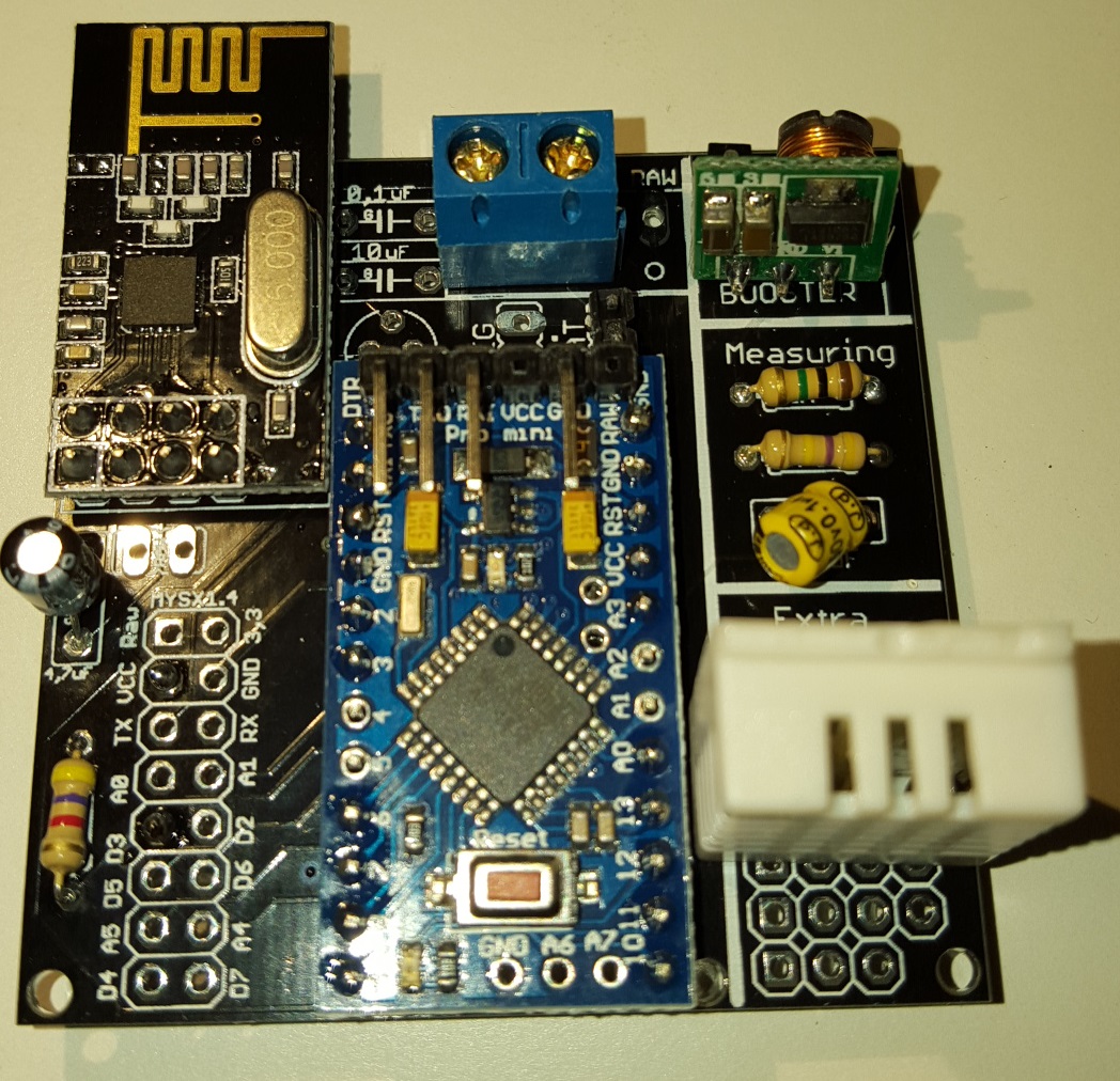
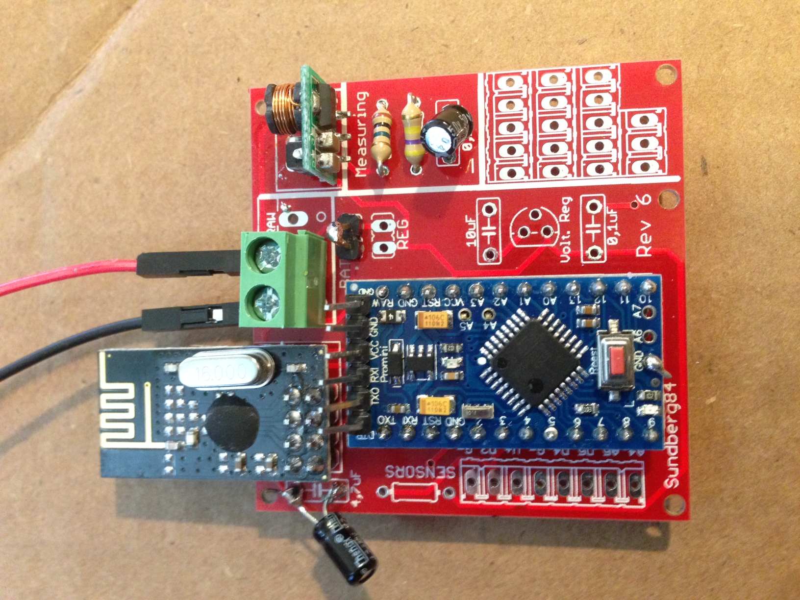
                                  I love this PCB. It makes things so much easier. I am having a little problem with the battery version though. I think I've got it wired up right. I've got the jumper. I've got the booster. But, when I plug in a battery (I've tried a 3.7 volt battery, outputting 3.3v - the one from the solar weather station project, and 2 or 4 AA batteries), I get a "Radio Init Fail" message in the serial monitor. Also, the LED at the back, the one near the reset button, does not light brightly. It initially flashes brightly, then nothing.

                                  I've wired it up two different times for the battery setup, and with neither am I getting the live radio.

                                  I am able to get a good radio with the 5v setup.

                                  0_1457023603222_IMG_2712 (1).JPG 0_1457023616266_IMG_2713 (1).JPG

                                  1 Reply Last reply
                                  0
                                  • sundberg84S Offline
                                    sundberg84S Offline
                                    sundberg84
                                    Hardware Contributor
                                    wrote on last edited by sundberg84
                                    #78

                                    Hi!
                                    @gentrfam
                                    It looks correctly wired. The radio (when bat jumper is selected) is feed directly from the battery, so you need to keep within the specs of the radio (0,9v- 3.6v).
                                    First thing I would do is measure volt over radio. Also measure volt over the arduino. Working backwards can give you a clue where it fails if its a power problem.

                                    My wild guess is that either its not a genuine/working NRF radio, or you have a cold/bad solder point on arduino and/or radio.

                                    I always check my radio before soldering them... a while back I counted that I have ordered 33 radios from Ebay and 3 of them was broken so far. So i have a Easy board just for radiocheck loaded with timeaware sketch.

                                    Controller: Proxmox VM - Home Assistant
                                    MySensors GW: Arduino Uno - W5100 Ethernet, Gw Shield Nrf24l01+ 2,4Ghz
                                    MySensors GW: Arduino Uno - Gw Shield RFM69, 433mhz
                                    RFLink GW - Arduino Mega + RFLink Shield, 433mhz

                                    gentrfamG 1 Reply Last reply
                                    0
                                    • sundberg84S sundberg84

                                      Hi!
                                      @gentrfam
                                      It looks correctly wired. The radio (when bat jumper is selected) is feed directly from the battery, so you need to keep within the specs of the radio (0,9v- 3.6v).
                                      First thing I would do is measure volt over radio. Also measure volt over the arduino. Working backwards can give you a clue where it fails if its a power problem.

                                      My wild guess is that either its not a genuine/working NRF radio, or you have a cold/bad solder point on arduino and/or radio.

                                      I always check my radio before soldering them... a while back I counted that I have ordered 33 radios from Ebay and 3 of them was broken so far. So i have a Easy board just for radiocheck loaded with timeaware sketch.

                                      gentrfamG Offline
                                      gentrfamG Offline
                                      gentrfam
                                      wrote on last edited by
                                      #79

                                      @sundberg84 Thank you. I checked, and out of the solar-powered battery, I'm actually just out of the radio spec - 3.7-4.0v. I'm going to try with a new radio, and a smaller battery to see if I fried this radio.

                                      In the meantime, I tried to run the battery through an LE33 regulator on a breadboard. (Eventually, I'd like to run the solar-battery through the measuring circuitry on the PCB.) Any idea why the LE33 would be outputting 0.6v?

                                      Thanks for your help. I'm afraid I'm a complete and total noob on this.

                                      1 Reply Last reply
                                      0
                                      • sundberg84S Offline
                                        sundberg84S Offline
                                        sundberg84
                                        Hardware Contributor
                                        wrote on last edited by sundberg84
                                        #80

                                        No, check incoming voltage to the LE33 - is this correct?
                                        Is the caps oriented (ground) correcly? (if you have any).
                                        Broken?

                                        Controller: Proxmox VM - Home Assistant
                                        MySensors GW: Arduino Uno - W5100 Ethernet, Gw Shield Nrf24l01+ 2,4Ghz
                                        MySensors GW: Arduino Uno - Gw Shield RFM69, 433mhz
                                        RFLink GW - Arduino Mega + RFLink Shield, 433mhz

                                        1 Reply Last reply
                                        0
                                        • fisherF Offline
                                          fisherF Offline
                                          fisher
                                          wrote on last edited by
                                          #81

                                          Hi,
                                          I already received PCB, soldered everything and I'm stuck with reliable radio quality. It works good only when I keep touching antenna on nrf board with my finger. Once I release my finger I've got st=fail.
                                          I've soldered two boards already, tried with two different radios and have same results
                                          I use nrf24L01+ with internal antenna and 5v pro mini, voltage regulator and caps (100nF, 10uF and 4,7uF) as well.

                                          Do you have any ideas what can be wrong?
                                          0_1457048331343_2016-03-04 00.34.16.jpg
                                          0_1457048341100_2016-03-04 00.34.32.jpg

                                          S 1 Reply Last reply
                                          0
                                          Reply
                                          • Reply as topic
                                          Log in to reply
                                          • Oldest to Newest
                                          • Newest to Oldest
                                          • Most Votes


                                          18

                                          Online

                                          11.7k

                                          Users

                                          11.2k

                                          Topics

                                          113.0k

                                          Posts


                                          Copyright 2019 TBD   |   Forum Guidelines   |   Privacy Policy   |   Terms of Service
                                          • Login

                                          • Don't have an account? Register

                                          • Login or register to search.
                                          • First post
                                            Last post
                                          0
                                          • OpenHardware.io
                                          • Categories
                                          • Recent
                                          • Tags
                                          • Popular