INA219 DC Current Sensor
-
@HighSierraJoe said:
send the voltage and current data over
A couple of new variables for this would make sense. V_VOLTAGE and V_CURRENT perhaps?
They will show up under the Advanced tab for the time being. If you need to display it on the main device you'll have te hack the existing power device
.I've ordered parts for a non invasive Power Meter Sensor. Hope to create some instructions for this as webb when the things arrive. But this would fit on the same instruction page among with this type of sensors.
-
No way to get this working in 1.4 with displayed values before release? ;-)
-
@HighSierraJoe said:
send the voltage and current data over
A couple of new variables for this would make sense. V_VOLTAGE and V_CURRENT perhaps?
They will show up under the Advanced tab for the time being. If you need to display it on the main device you'll have te hack the existing power device
.I've ordered parts for a non invasive Power Meter Sensor. Hope to create some instructions for this as webb when the things arrive. But this would fit on the same instruction page among with this type of sensors.
-
Yes @epierre,
I bought a couple of these split core currect transformers and a 10 pack of female connectors.
Planned on following these instructions:
http://www.homautomation.org/2013/09/17/current-monitoring-with-non-invasive-sensor-and-arduino/http://openenergymonitor.org/emon/buildingblocks/ct-sensors-interface
-
Thanks for the replies!
@hek
I added the 2 new variables as you suggested. I already hacked the power device so the values are being displayed in the proper amps and volts, but having a hard time getting notifications to work properly! So with that being said you have my vote as well to include this in 1.4 as its own device showing DC volts and amps or even converted to watts is acceptable.These split core CT's look pretty nice. They could make a cheap replacement to other energy monitors like TED5000 and would take up less room in your panel if you can tie multiple CT pairs into one wireless sensor node.
-
On the current transformers (CT). Need a little caution with these. If they are energized with no burden resistor and do not have any protective measures in place like zeners, then the output Voltage can be very high. For example if the transformer is one turn to 2000 turns, like Hek's example transformer and we assume the open circuit resistance is 10 MOhms (it's probably higher) and the primary current flow is just one 1 Amp, then the output Voltage can reach 5000 Volts. (1/2000)*10,000,000=5000. The Voltage produced is ultimately moderated by core saturation. I've seen these things produce nice sparks. However Hek's transformer uses a protective measure to avoid this: two zeners in series across the secondary. The linked article under "6. Operation without an external burden."
http://openenergymonitor.org/emon/buildingblocks/report-yhdc-sct-013-000-current-transformer
indicates the Voltage is clamped to +/-22V by the zeners. This is still enough to fry your Arduino ADC, if the required burden resistor is accidentally incorrectly connected. Likewise probably best not to unplug & plug in the CT, while its got power going through the primary. It may be more prudent to hardwire the CT to the Arduino.
-
I have a couple of those CT too but havn't had time to learn what is needed to do a correct readout. I'll follow this and would like to follow your progress.. :) Mine has internal burden resistor and some protecive diods I think.
-
Very interesting, I would like to follow!
-
Has anyone made any progress implementing the AC current sensor or is there a My Sensor plugin?
-
I have some ACS712 current sensors on order.
They are easy to use as they give a voltage that corresponds to the current flowing through it.
I am planning to use them to measure current in my LED pwm-dimmer.
I am going to power them with old laptop charger ~18V and limit current depending on length of led-strip. -
Just ordered a 100A sensor, going to look to tackle this sometime early January. Will post details if no one else has by then.
-
I am using ACS712 current sensor with the relay actuator code to sense if someone has manually switched on the light from the physical switch mounted on the walls. If I can help ping me.
Hello @mainali
Can you provide more details regarding the ACS712 current sensor ?
Maybe a drawing on ho to connect to the arduino nand the sketch ?Thanks
-
I am using a two way switch to control my device. The idea is to control the state from arduino as well as physical switch parallely.
Physical switch ON, Arduino can switch it OFF
Arduino switches it ON, Physical switch whatever be the state on push should switch it OFF.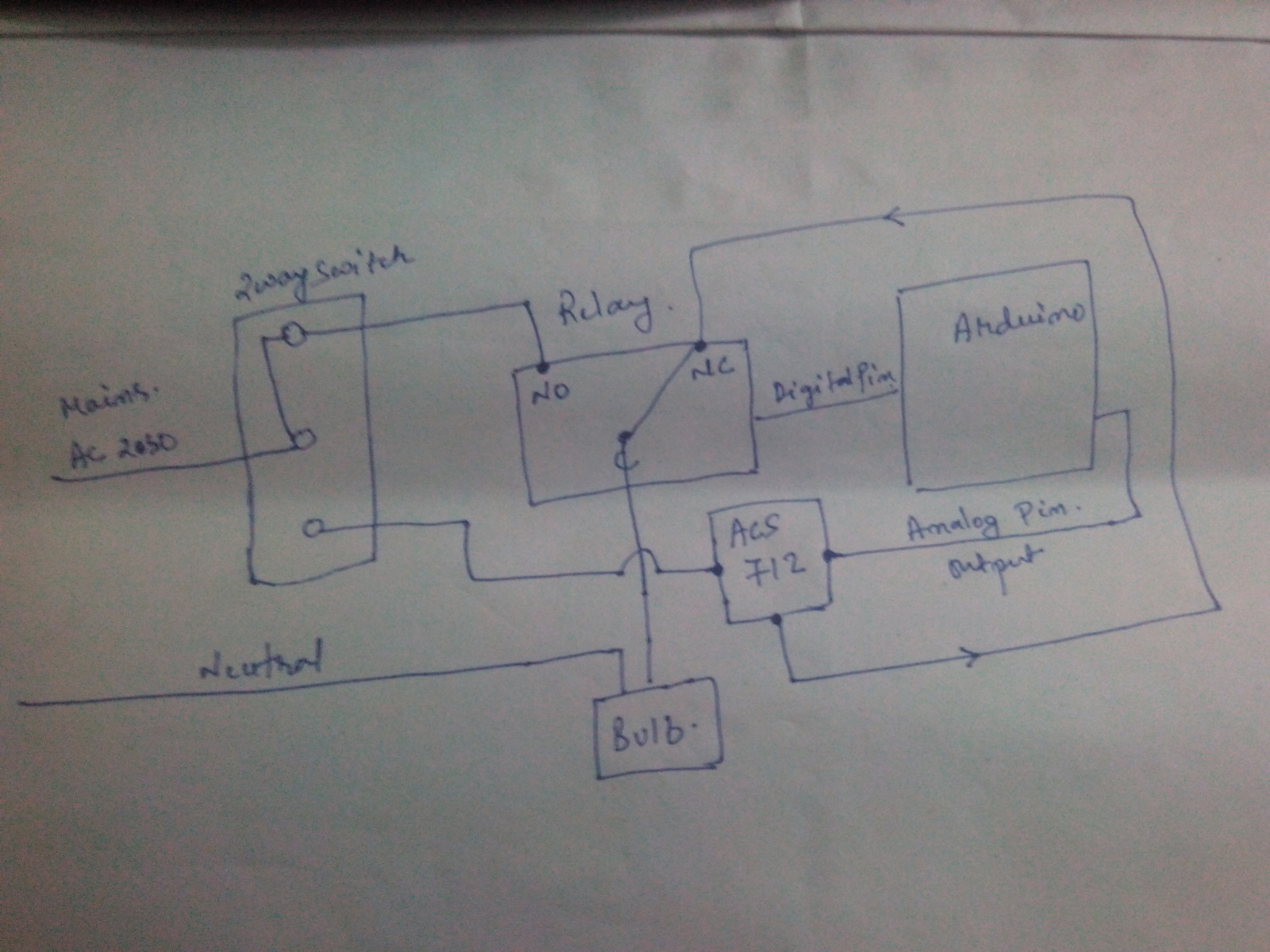
I have used the Relay actuator example code from mysensor and little more code which I found in arduino forum.
I am not able to use the plugin to embed the code, anyways the following is the code.
// Example sketch showing how to control physical relays.
// This example will remember relay state even after power failure.#include <MySensor.h>
#include <SPI.h>#define RELAY_1 2 // Arduino Digital I/O pin number for first relay (second on pin+1 etc)
#define RELAY_2 3
#define NUMBER_OF_RELAYS 2 // Total number of attached relays
#define RELAY_ON 1 // GPIO value to write to turn on attached relay
#define RELAY_OFF 0 // GPIO value to write to turn off attached relay
#define CHILD_ID 1#define CURRENT_SENSOR A0 // Analog input pin that sensor is attached to
MyMessage msg(CHILD_ID, V_TRIPPED); //Using this as the message to report the physical switch on statusfloat amplitude_current; //amplitude current
float effective_value;
bool switch_1_on;
int count = 0;
MySensor gw;void setup()
{
// Initialize library and add callback for incoming messages
gw.begin(incomingMessage, 21, true);// Send the sketch version information to the gateway and Controller
gw.sendSketchInfo("Relay with current sensor", "1.0");
pins_init();// Fetch relay status
for (int sensor=1, pin=RELAY_1; sensor<=NUMBER_OF_RELAYS;sensor++, pin++) {
// Register all sensors to gw (they will be created as child devices)
gw.present(sensor, S_LIGHT);
// Then set relay pins in output mode
pinMode(pin, OUTPUT);
// Set relay to last known state (using eeprom storage)
digitalWrite(pin, gw.loadState(sensor)?RELAY_ON:RELAY_OFF);
}
}void loop()
{
int sensor_max;
sensor_max = getMaxValue();
Serial.print("sensor_max = ");
Serial.println(sensor_max);
//the VCC on the Grove interface of the sensor is 5v
amplitude_current=(float)(sensor_max-512)/10245/1851000000;
effective_value=amplitude_current/1.414;
//minimum_current=1/10245/1851000000/1.414=18.7(mA)
//Only for sinusoidal alternating current
Serial.println("The amplitude of the current is(in mA)");
Serial.println(amplitude_current,1);//Only one number after the decimal point
Serial.println("The effective value of the current is(in mA)");
Serial.println(effective_value,1);if (count == 0 && amplitude_current > 30) { switch_1_on = true; Serial.println("physical switch on"); gw.send(msg.set(switch_1_on?"1":"0")); count = 1 ; } else { count = 0 ; }// Alway process incoming messages whenever possible
gw.process();
}void incomingMessage(const MyMessage &message) {
// We only expect one type of message from controller. But we better check anyway.
if (message.type == V_FAN) {
Serial.println("Message arrived for FAN");
Serial.println(message.sensor);
for(int i=4 ; i<=7; i++) {
digitalWrite(i,0);
}
}
if (message.type==V_LIGHT) {
// Change relay state
digitalWrite(message.sensor-1+RELAY_1, message.getBool()?RELAY_ON:RELAY_OFF);
// Store state in eeprom
gw.saveState(message.sensor, message.getBool());
// Write some debug info
Serial.print("Incoming change for sensor:");
Serial.print(message.sensor);
Serial.print(", New status: ");
Serial.println(message.getBool());
}
}void pins_init()
{
pinMode(CURRENT_SENSOR, INPUT);
}
/Function: Sample for 1000ms and get the maximum value from the S pin/
int getMaxValue()
{
int sensorValue; //value read from the sensor
int sensorMax = 0;
uint32_t start_time = millis();
while((millis()-start_time) < 1000)//sample for 1000ms
{
sensorValue = analogRead(CURRENT_SENSOR);
if (sensorValue > sensorMax)
{
/record the maximum sensor value/
sensorMax = sensorValue;
}
}
return sensorMax;
} -
Thanks !
-
has anyone made something usefull with the ACS712 yet ?
-
I am using a two way switch to control my device. The idea is to control the state from arduino as well as physical switch parallely.
Physical switch ON, Arduino can switch it OFF
Arduino switches it ON, Physical switch whatever be the state on push should switch it OFF.I have used the Relay actuator example code from mysensor and little more code which I found in arduino forum.
I am not able to use the plugin to embed the code, anyways the following is the code.
// Example sketch showing how to control physical relays.
// This example will remember relay state even after power failure.#include <MySensor.h>
#include <SPI.h>#define RELAY_1 2 // Arduino Digital I/O pin number for first relay (second on pin+1 etc)
#define RELAY_2 3
#define NUMBER_OF_RELAYS 2 // Total number of attached relays
#define RELAY_ON 1 // GPIO value to write to turn on attached relay
#define RELAY_OFF 0 // GPIO value to write to turn off attached relay
#define CHILD_ID 1#define CURRENT_SENSOR A0 // Analog input pin that sensor is attached to
MyMessage msg(CHILD_ID, V_TRIPPED); //Using this as the message to report the physical switch on statusfloat amplitude_current; //amplitude current
float effective_value;
bool switch_1_on;
int count = 0;
MySensor gw;void setup()
{
// Initialize library and add callback for incoming messages
gw.begin(incomingMessage, 21, true);// Send the sketch version information to the gateway and Controller
gw.sendSketchInfo("Relay with current sensor", "1.0");
pins_init();// Fetch relay status
for (int sensor=1, pin=RELAY_1; sensor<=NUMBER_OF_RELAYS;sensor++, pin++) {
// Register all sensors to gw (they will be created as child devices)
gw.present(sensor, S_LIGHT);
// Then set relay pins in output mode
pinMode(pin, OUTPUT);
// Set relay to last known state (using eeprom storage)
digitalWrite(pin, gw.loadState(sensor)?RELAY_ON:RELAY_OFF);
}
}void loop()
{
int sensor_max;
sensor_max = getMaxValue();
Serial.print("sensor_max = ");
Serial.println(sensor_max);
//the VCC on the Grove interface of the sensor is 5v
amplitude_current=(float)(sensor_max-512)/10245/1851000000;
effective_value=amplitude_current/1.414;
//minimum_current=1/10245/1851000000/1.414=18.7(mA)
//Only for sinusoidal alternating current
Serial.println("The amplitude of the current is(in mA)");
Serial.println(amplitude_current,1);//Only one number after the decimal point
Serial.println("The effective value of the current is(in mA)");
Serial.println(effective_value,1);if (count == 0 && amplitude_current > 30) { switch_1_on = true; Serial.println("physical switch on"); gw.send(msg.set(switch_1_on?"1":"0")); count = 1 ; } else { count = 0 ; }// Alway process incoming messages whenever possible
gw.process();
}void incomingMessage(const MyMessage &message) {
// We only expect one type of message from controller. But we better check anyway.
if (message.type == V_FAN) {
Serial.println("Message arrived for FAN");
Serial.println(message.sensor);
for(int i=4 ; i<=7; i++) {
digitalWrite(i,0);
}
}
if (message.type==V_LIGHT) {
// Change relay state
digitalWrite(message.sensor-1+RELAY_1, message.getBool()?RELAY_ON:RELAY_OFF);
// Store state in eeprom
gw.saveState(message.sensor, message.getBool());
// Write some debug info
Serial.print("Incoming change for sensor:");
Serial.print(message.sensor);
Serial.print(", New status: ");
Serial.println(message.getBool());
}
}void pins_init()
{
pinMode(CURRENT_SENSOR, INPUT);
}
/Function: Sample for 1000ms and get the maximum value from the S pin/
int getMaxValue()
{
int sensorValue; //value read from the sensor
int sensorMax = 0;
uint32_t start_time = millis();
while((millis()-start_time) < 1000)//sample for 1000ms
{
sensorValue = analogRead(CURRENT_SENSOR);
if (sensorValue > sensorMax)
{
/record the maximum sensor value/
sensorMax = sensorValue;
}
}
return sensorMax;
}@mainali said in INA219 DC Current Sensor:
MySensor gw;
I am building similar system. However, i am facing a lot of difficulties to make the ACS712 working. I have tried your code as well without success. The effective value of the current is always 0 mA even if the light is ON.
For the moment, i am testing with 5V current and i switch on a LED. maybe the current is too low to make working my 20A ACS712?
If anyone has some ideas, it will be very greatful :) Thanks a lot.