I can get the WaterMeterPulseSensor working.
-
Dear all,
i am working to get the Water Pulse meter on Arduino to send the data to Domoticz. (through an RFXtrx322e)
i am rather new to this, but the site looked easy to get this working, but apparently its i bit harder than i thought.
So i am in need of your help.I use:
- Arduino IDE 1.6.7 (linux 64Bit)
- Mysensors 1.5 Library
- Arduino UNO R3
- RFM69HW (rev2) 433MHz (connected through a 3,3V regulator, including 4,7uF capacitor)
i loaded the sketch, and i only get 'radio init fail'
In MyConfig.h i enabled
#define RFM69_FREQUENCY RF69_433MHZi am not sure about enabling, cause till now it did'nt matter
//#define MY_SIGNING_FEATUREIn MyTransportRFM69.h i changed: false in to true
bool isRFM69HW=trueWhat did i miss, or do i need to change/check.
Thanx in advance.
-
The code would be as i got it from the site, and its wired like this
Only then for an UNO R3, that would look like:
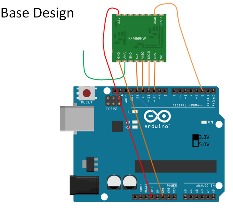
But with the only differences
- it has an 5V to 3,3V regulator and 4.7uF capacitor (instead of directly to 3.3V on the UNO board (wich also doesńt work...))
(3.3V is supplied to the RFM69HW board, i got that checked / measured) - GND between ANA and SCK is also connected to ground.
/** * The MySensors Arduino library handles the wireless radio link and protocol * between your home built sensors/actuators and HA controller of choice. * The sensors forms a self healing radio network with optional repeaters. Each * repeater and gateway builds a routing tables in EEPROM which keeps track of the * network topology allowing messages to be routed to nodes. * * Created by Henrik Ekblad <henrik.ekblad@mysensors.org> * Copyright (C) 2013-2015 Sensnology AB * Full contributor list: https://github.com/mysensors/Arduino/graphs/contributors * * Documentation: http://www.mysensors.org * Support Forum: http://forum.mysensors.org * * This program is free software; you can redistribute it and/or * modify it under the terms of the GNU General Public License * version 2 as published by the Free Software Foundation. * ******************************* * * REVISION HISTORY * Version 1.0 - Henrik Ekblad * Version 1.1 - GizMoCuz * * DESCRIPTION * Use this sensor to measure volume and flow of your house watermeter. * You need to set the correct pulsefactor of your meter (pulses per m3). * The sensor starts by fetching current volume reading from gateway (VAR 1). * Reports both volume and flow back to gateway. * * Unfortunately millis() won't increment when the Arduino is in * sleepmode. So we cannot make this sensor sleep if we also want * to calculate/report flow. * http://www.mysensors.org/build/pulse_water */ #include <MySensor.h> #include <SPI.h> #define DIGITAL_INPUT_SENSOR 3 // The digital input you attached your sensor. (Only 2 and 3 generates interrupt!) #define SENSOR_INTERRUPT DIGITAL_INPUT_SENSOR-2 // Usually the interrupt = pin -2 (on uno/nano anyway) #define PULSE_FACTOR 1000 // Nummber of blinks per m3 of your meter (One rotation/liter) #define SLEEP_MODE false // flowvalue can only be reported when sleep mode is false. #define MAX_FLOW 40 // Max flow (l/min) value to report. This filters outliers. #define CHILD_ID 1 // Id of the sensor child unsigned long SEND_FREQUENCY = 30000; // Minimum time between send (in milliseconds). We don't want to spam the gateway. MySensor gw; MyMessage flowMsg(CHILD_ID,V_FLOW); MyMessage volumeMsg(CHILD_ID,V_VOLUME); MyMessage lastCounterMsg(CHILD_ID,V_VAR1); double ppl = ((double)PULSE_FACTOR)/1000; // Pulses per liter volatile unsigned long pulseCount = 0; volatile unsigned long lastBlink = 0; volatile double flow = 0; boolean pcReceived = false; unsigned long oldPulseCount = 0; unsigned long newBlink = 0; double oldflow = 0; double volume =0; double oldvolume =0; unsigned long lastSend =0; unsigned long lastPulse =0; void setup() { gw.begin(incomingMessage); // initialize our digital pins internal pullup resistor so one pulse switches from high to low (less distortion) pinMode(DIGITAL_INPUT_SENSOR, INPUT_PULLUP); // Send the sketch version information to the gateway and Controller gw.sendSketchInfo("Water Meter", "1.1"); // Register this device as Waterflow sensor gw.present(CHILD_ID, S_WATER); pulseCount = oldPulseCount = 0; // Fetch last known pulse count value from gw gw.request(CHILD_ID, V_VAR1); lastSend = lastPulse = millis(); attachInterrupt(SENSOR_INTERRUPT, onPulse, FALLING); } void loop() { gw.process(); unsigned long currentTime = millis(); // Only send values at a maximum frequency or woken up from sleep if (SLEEP_MODE || (currentTime - lastSend > SEND_FREQUENCY)) { lastSend=currentTime; if (!pcReceived) { //Last Pulsecount not yet received from controller, request it again gw.request(CHILD_ID, V_VAR1); return; } if (!SLEEP_MODE && flow != oldflow) { oldflow = flow; Serial.print("l/min:"); Serial.println(flow); // Check that we dont get unresonable large flow value. // could hapen when long wraps or false interrupt triggered if (flow<((unsigned long)MAX_FLOW)) { gw.send(flowMsg.set(flow, 2)); // Send flow value to gw } } // No Pulse count received in 2min if(currentTime - lastPulse > 120000){ flow = 0; } // Pulse count has changed if ((pulseCount != oldPulseCount)||(!SLEEP_MODE)) { oldPulseCount = pulseCount; Serial.print("pulsecount:"); Serial.println(pulseCount); gw.send(lastCounterMsg.set(pulseCount)); // Send pulsecount value to gw in VAR1 double volume = ((double)pulseCount/((double)PULSE_FACTOR)); if ((volume != oldvolume)||(!SLEEP_MODE)) { oldvolume = volume; Serial.print("volume:"); Serial.println(volume, 3); gw.send(volumeMsg.set(volume, 3)); // Send volume value to gw } } } if (SLEEP_MODE) { gw.sleep(SEND_FREQUENCY); } } void incomingMessage(const MyMessage &message) { if (message.type==V_VAR1) { unsigned long gwPulseCount=message.getULong(); pulseCount += gwPulseCount; flow=oldflow=0; Serial.print("Received last pulse count from gw:"); Serial.println(pulseCount); pcReceived = true; } } void onPulse() { if (!SLEEP_MODE) { unsigned long newBlink = micros(); unsigned long interval = newBlink-lastBlink; if (interval!=0) { lastPulse = millis(); if (interval<500000L) { // Sometimes we get interrupt on RISING, 500000 = 0.5sek debounce ( max 120 l/min) return; } flow = (60000000.0 /interval) / ppl; } lastBlink = newBlink; } pulseCount++; } - it has an 5V to 3,3V regulator and 4.7uF capacitor (instead of directly to 3.3V on the UNO board (wich also doesńt work...))
-
The code would be as i got it from the site, and its wired like this
Only then for an UNO R3, that would look like:
But with the only differences
- it has an 5V to 3,3V regulator and 4.7uF capacitor (instead of directly to 3.3V on the UNO board (wich also doesńt work...))
(3.3V is supplied to the RFM69HW board, i got that checked / measured) - GND between ANA and SCK is also connected to ground.
/** * The MySensors Arduino library handles the wireless radio link and protocol * between your home built sensors/actuators and HA controller of choice. * The sensors forms a self healing radio network with optional repeaters. Each * repeater and gateway builds a routing tables in EEPROM which keeps track of the * network topology allowing messages to be routed to nodes. * * Created by Henrik Ekblad <henrik.ekblad@mysensors.org> * Copyright (C) 2013-2015 Sensnology AB * Full contributor list: https://github.com/mysensors/Arduino/graphs/contributors * * Documentation: http://www.mysensors.org * Support Forum: http://forum.mysensors.org * * This program is free software; you can redistribute it and/or * modify it under the terms of the GNU General Public License * version 2 as published by the Free Software Foundation. * ******************************* * * REVISION HISTORY * Version 1.0 - Henrik Ekblad * Version 1.1 - GizMoCuz * * DESCRIPTION * Use this sensor to measure volume and flow of your house watermeter. * You need to set the correct pulsefactor of your meter (pulses per m3). * The sensor starts by fetching current volume reading from gateway (VAR 1). * Reports both volume and flow back to gateway. * * Unfortunately millis() won't increment when the Arduino is in * sleepmode. So we cannot make this sensor sleep if we also want * to calculate/report flow. * http://www.mysensors.org/build/pulse_water */ #include <MySensor.h> #include <SPI.h> #define DIGITAL_INPUT_SENSOR 3 // The digital input you attached your sensor. (Only 2 and 3 generates interrupt!) #define SENSOR_INTERRUPT DIGITAL_INPUT_SENSOR-2 // Usually the interrupt = pin -2 (on uno/nano anyway) #define PULSE_FACTOR 1000 // Nummber of blinks per m3 of your meter (One rotation/liter) #define SLEEP_MODE false // flowvalue can only be reported when sleep mode is false. #define MAX_FLOW 40 // Max flow (l/min) value to report. This filters outliers. #define CHILD_ID 1 // Id of the sensor child unsigned long SEND_FREQUENCY = 30000; // Minimum time between send (in milliseconds). We don't want to spam the gateway. MySensor gw; MyMessage flowMsg(CHILD_ID,V_FLOW); MyMessage volumeMsg(CHILD_ID,V_VOLUME); MyMessage lastCounterMsg(CHILD_ID,V_VAR1); double ppl = ((double)PULSE_FACTOR)/1000; // Pulses per liter volatile unsigned long pulseCount = 0; volatile unsigned long lastBlink = 0; volatile double flow = 0; boolean pcReceived = false; unsigned long oldPulseCount = 0; unsigned long newBlink = 0; double oldflow = 0; double volume =0; double oldvolume =0; unsigned long lastSend =0; unsigned long lastPulse =0; void setup() { gw.begin(incomingMessage); // initialize our digital pins internal pullup resistor so one pulse switches from high to low (less distortion) pinMode(DIGITAL_INPUT_SENSOR, INPUT_PULLUP); // Send the sketch version information to the gateway and Controller gw.sendSketchInfo("Water Meter", "1.1"); // Register this device as Waterflow sensor gw.present(CHILD_ID, S_WATER); pulseCount = oldPulseCount = 0; // Fetch last known pulse count value from gw gw.request(CHILD_ID, V_VAR1); lastSend = lastPulse = millis(); attachInterrupt(SENSOR_INTERRUPT, onPulse, FALLING); } void loop() { gw.process(); unsigned long currentTime = millis(); // Only send values at a maximum frequency or woken up from sleep if (SLEEP_MODE || (currentTime - lastSend > SEND_FREQUENCY)) { lastSend=currentTime; if (!pcReceived) { //Last Pulsecount not yet received from controller, request it again gw.request(CHILD_ID, V_VAR1); return; } if (!SLEEP_MODE && flow != oldflow) { oldflow = flow; Serial.print("l/min:"); Serial.println(flow); // Check that we dont get unresonable large flow value. // could hapen when long wraps or false interrupt triggered if (flow<((unsigned long)MAX_FLOW)) { gw.send(flowMsg.set(flow, 2)); // Send flow value to gw } } // No Pulse count received in 2min if(currentTime - lastPulse > 120000){ flow = 0; } // Pulse count has changed if ((pulseCount != oldPulseCount)||(!SLEEP_MODE)) { oldPulseCount = pulseCount; Serial.print("pulsecount:"); Serial.println(pulseCount); gw.send(lastCounterMsg.set(pulseCount)); // Send pulsecount value to gw in VAR1 double volume = ((double)pulseCount/((double)PULSE_FACTOR)); if ((volume != oldvolume)||(!SLEEP_MODE)) { oldvolume = volume; Serial.print("volume:"); Serial.println(volume, 3); gw.send(volumeMsg.set(volume, 3)); // Send volume value to gw } } } if (SLEEP_MODE) { gw.sleep(SEND_FREQUENCY); } } void incomingMessage(const MyMessage &message) { if (message.type==V_VAR1) { unsigned long gwPulseCount=message.getULong(); pulseCount += gwPulseCount; flow=oldflow=0; Serial.print("Received last pulse count from gw:"); Serial.println(pulseCount); pcReceived = true; } } void onPulse() { if (!SLEEP_MODE) { unsigned long newBlink = micros(); unsigned long interval = newBlink-lastBlink; if (interval!=0) { lastPulse = millis(); if (interval<500000L) { // Sometimes we get interrupt on RISING, 500000 = 0.5sek debounce ( max 120 l/min) return; } flow = (60000000.0 /interval) / ppl; } lastBlink = newBlink; } pulseCount++; }This post is deleted! - it has an 5V to 3,3V regulator and 4.7uF capacitor (instead of directly to 3.3V on the UNO board (wich also doesńt work...))
-
The wiring instructions say "NOTE: The NSS, MOSI and SCK are not 5V tolerant on RFM69. You will need to use a level converter if you're using a 5V Arduino." The Uno is 5V. So you might have fried your radio :( Except that everything looks fine to me but I haven't tried the RFM69 myself.
-
The wiring instructions say "NOTE: The NSS, MOSI and SCK are not 5V tolerant on RFM69. You will need to use a level converter if you're using a 5V Arduino." The Uno is 5V. So you might have fried your radio :( Except that everything looks fine to me but I haven't tried the RFM69 myself.
@mfalkvidd
i have the RFM69 HW connected through a 3,3V regulator (including capacitor), so there was never 5V on de Radio board.
iĺl add it to the first post aswell. -
@mfalkvidd
i have the RFM69 HW connected through a 3,3V regulator (including capacitor), so there was never 5V on de Radio board.
iĺl add it to the first post aswell. -
ouch, i need to look in to that, but then it might me true the board is damaged...
(Some other sketches seem to report data to the serial monitor, but i am not sure if the RFM69HW module is working.)