💬 Very narrow and minimal switch node
-
Updated the design files with version 1-1. Explanation of what this version does will follow later (not that much more, but I2C extension is now an option).
-
Very nice! It would be perfect if it would get an atsha204a and a flash module.
Greets Eddie@meddie not sure that would even fit on the board, have you seen the size?
-
@GertSanders
the PCB must be a little bit longer. But the two chips are not big. The ATSHA201A is very small its a 3 PIN smd chip, and the flash chip is 8 pin. -
@meddie I try to stay within the 50mm length limit, so that we can have the boards produced in a 50x50 format. Making it longer means we need to go to a 100x100mm format, and that makes it more costly (not necessarily per board, but some people do not need +50 sensor boards).
At the moment we get 5 of these nodes within the 50x50mm limit, so a prototype run already produces 50 boards.
Anyway, I'm not exscluding this idea, I just do not have a need for it now. The minimal node is meant to be minimal, not a complete MySensors node. If you need that, there is always the Sensebender Micro (which has it all built in).
-
@GertSanders I'm a fan of your boards. I have your 20x30mm board, AC/Capable 50x50mm board (my favorite) and now I ordered your v1.1 of your narrow board because you are agree my suggestion for I2C port with jumper ;)
-
@GertSanders , 1 question, you have specified 1/8w resistor... did you know if 1/4w fit on narrow board ?
-
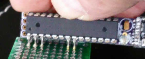
@Carl H If the 1/4w resistor can fit in pads 7mm apart from each other, then should be no problem. But they need to stay flat to fit under the processor.
-
Hello, @GertSanders I would like to ask. How I understand it is possible to load different sketch type to this board and then I could use it like one of MySensors sketches? For example could I load MyS humidity sketch? Thanks!
@jacikaas: to program the processor, you need to remove it from the board and program it on a breadboard or another board with ftdi interface.
But you can load a sketch like the humidity sensor sketch if you add a I2C sensor like a SI7021. I plan to do just that. -
The very narrow boards v1-1 have arrived :-)
-
The latest member of my growing sensor family, a reedswitch sensor with wakeup from power down by change on pin 2, wakeup every 23 hours to report battery voltage, and of course a blinky light when these things happen :-)
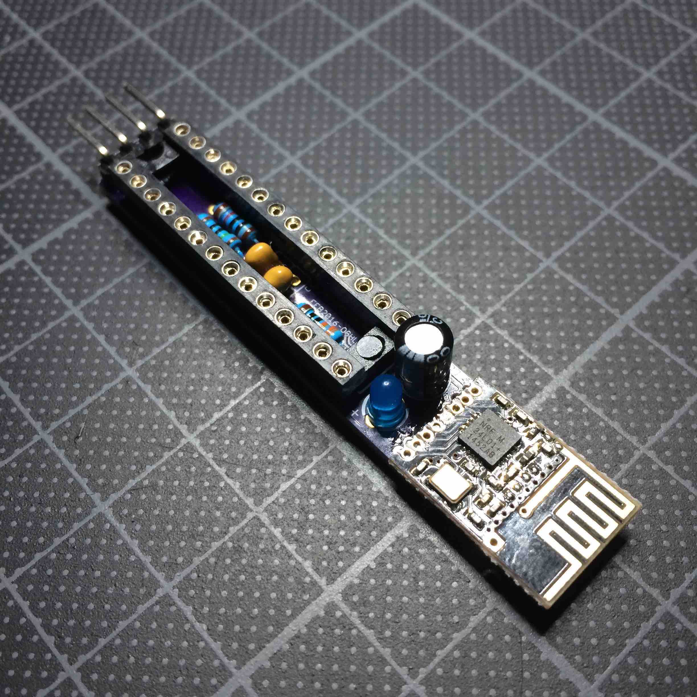
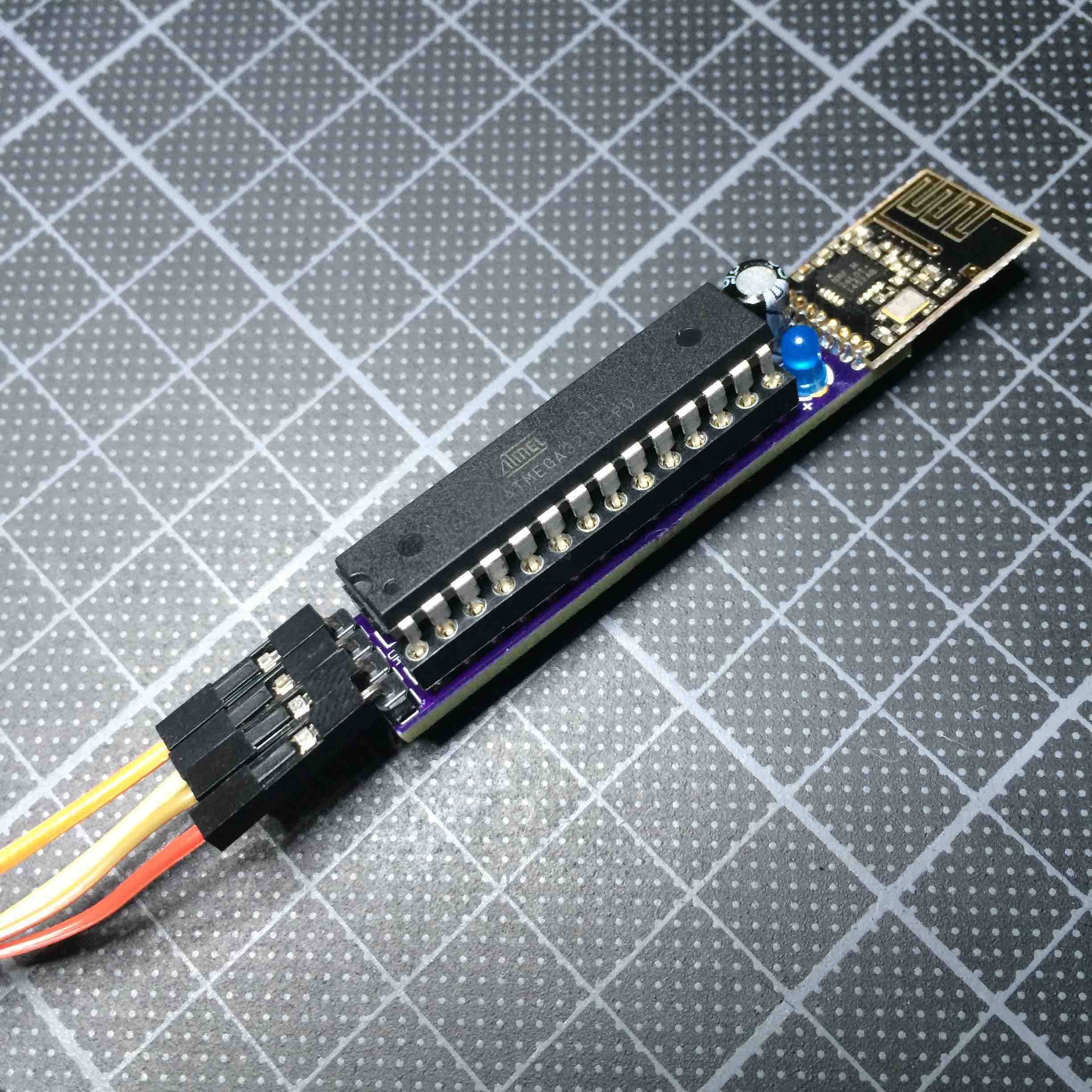
Just tested and found to be OK. Next board will be set up for using a I2C module (will be my smallest temperature sensor yet). Time for a glas of WestVleeteren and rest.
-
The latest member of my growing sensor family, a reedswitch sensor with wakeup from power down by change on pin 2, wakeup every 23 hours to report battery voltage, and of course a blinky light when these things happen :-)
Just tested and found to be OK. Next board will be set up for using a I2C module (will be my smallest temperature sensor yet). Time for a glas of WestVleeteren and rest.
@GertSanders said:
Just tested and found to be OK. Next board will be set up for using a I2C module (will be my smallest temperature sensor yet). Time for a glas of WestVleeteren and rest.
@GertSanders
Westvleteren Blonde is very nice :)
Can you please remind me the difference berwrrn v1 and 1-1?
I think it would be good to add FTDI connection, but the space is very limited -
@GertSanders said:
Just tested and found to be OK. Next board will be set up for using a I2C module (will be my smallest temperature sensor yet). Time for a glas of WestVleeteren and rest.
@GertSanders
Westvleteren Blonde is very nice :)
Can you please remind me the difference berwrrn v1 and 1-1?
I think it would be good to add FTDI connection, but the space is very limited@alexsh1 FTDI would be nice to reprogram more easily, but in my case I have a stable sketch which is loaded 1 time, and then the node is deployed. No point in providing extra pins or using boardspace if it is only used once or twice.
I saw that @AWI mentioned pogo-pins to make connections. Also a nice idea. In any case, my node is not designed to be flexible, and after programming I want to forget it. These nodes are sitting on doors and windows and need to do 1 thing only: show status of the reed-switched that are connected to them.
But adding some pads so that pogo pins can make contact to RX, TX and !RESET would still be possible.
It will be nice to see if a RFM69 radio can be connected by @carlierd . Looking forward to some pictures :-)
-
@GertSanders said:
Just tested and found to be OK. Next board will be set up for using a I2C module (will be my smallest temperature sensor yet). Time for a glas of WestVleeteren and rest.
@GertSanders
Westvleteren Blonde is very nice :)
Can you please remind me the difference berwrrn v1 and 1-1?
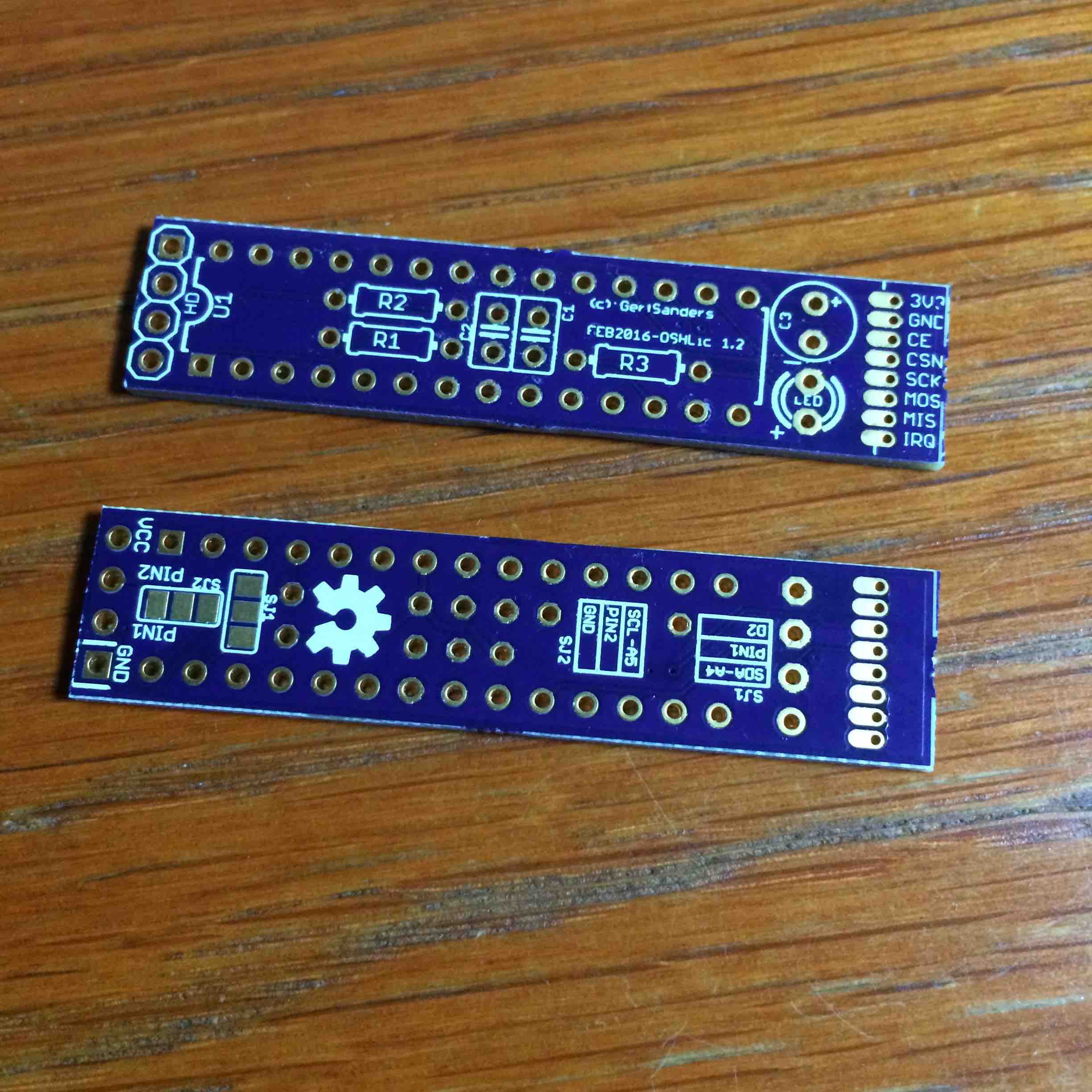
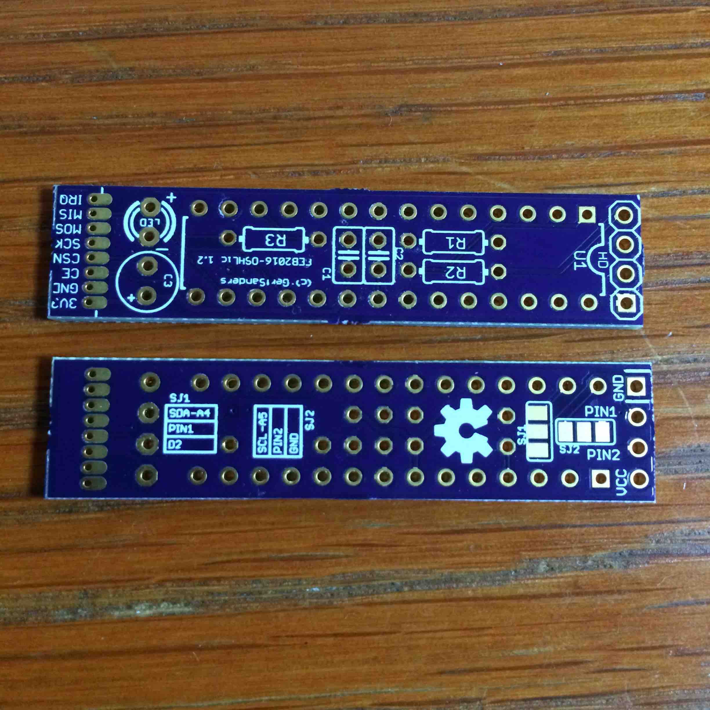
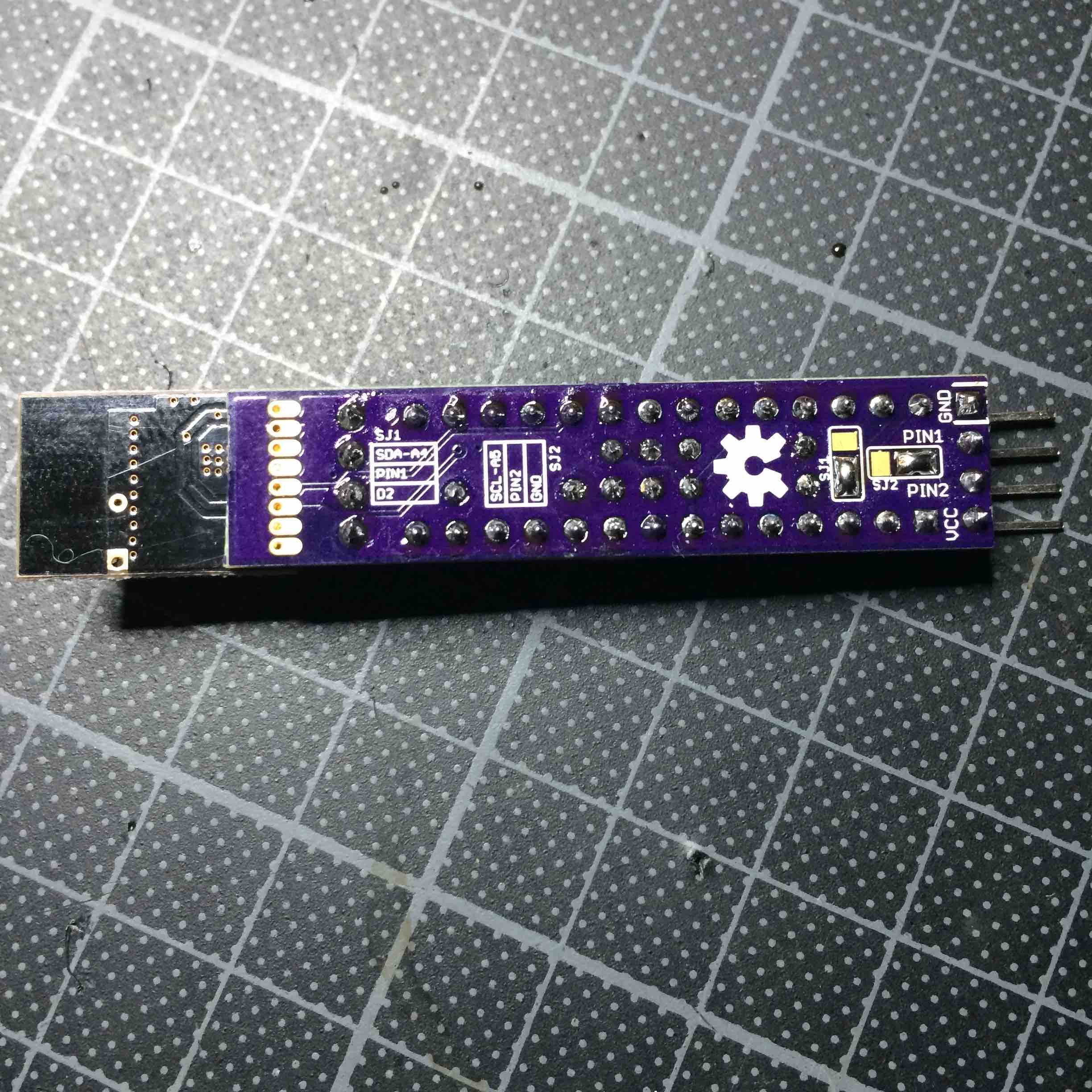
I think it would be good to add FTDI connection, but the space is very limitedThe difference between v1-0 and V1-1:
V1-0:
has 4 pins connected to VCC, GND, D2, D3 (in this sequence).
LED is connected to D8V1-1:
has 4 pins, of which 2 are fixed. Vcc and GND are at the outside (closest to board edge).
The two pins in the middle (pin1 and pin2) can be connected to two different pins each by using the solder jumper.
pin1 can be connected to SDA/A4 or to D2
pin2 can be connected to SCL/A5 or to GND
LED is connected to D6 -
@alexsh1 FTDI would be nice to reprogram more easily, but in my case I have a stable sketch which is loaded 1 time, and then the node is deployed. No point in providing extra pins or using boardspace if it is only used once or twice.
I saw that @AWI mentioned pogo-pins to make connections. Also a nice idea. In any case, my node is not designed to be flexible, and after programming I want to forget it. These nodes are sitting on doors and windows and need to do 1 thing only: show status of the reed-switched that are connected to them.
But adding some pads so that pogo pins can make contact to RX, TX and !RESET would still be possible.
It will be nice to see if a RFM69 radio can be connected by @carlierd . Looking forward to some pictures :-)
@GertSanders A bit off a hassle, but I don't need pads... ;-)
-
@GertSanders A bit off a hassle, but I don't need pads... ;-)
@AWI very nice, where did you buy the pins ?
-
@AWI very nice, where did you buy the pins ?
@GertSanders I used these pins. These work for me but there are many other types in the same store which could serve your needs better.