Has anyone made a 2 or 4 channel relay , and is that worked correct ?
-
-
@Reza said:
How do I check this?
See question 1 in http://forum.mysensors.org/topic/666/debug-faq-and-how-ask-for-help
@mfalkvidd
thank you -
@mfalkvidd said:
What does the serial debug output say?
hi I build a 2channel relay but this is same problem ( just one relay is working
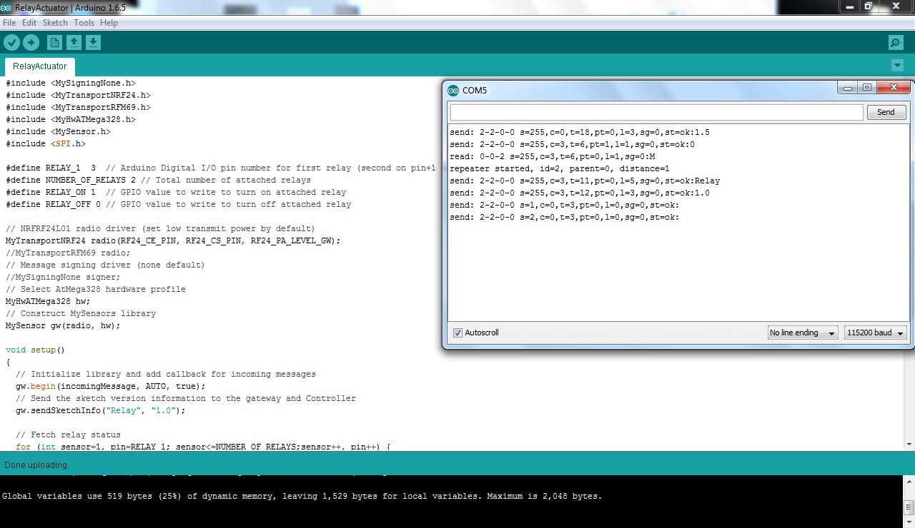
it is serial manitor :
send: 2-2-0-0 s=255,c=0,t=18,pt=0,l=3,sg=0,st=ok:1.5
send: 2-2-0-0 s=255,c=3,t=6,pt=1,l=1,sg=0,st=ok:0
read: 0-0-2 s=255,c=3,t=6,pt=0,l=1,sg=0:M
repeater started, id=2, parent=0, distance=1
send: 2-2-0-0 s=255,c=3,t=11,pt=0,l=5,sg=0,st=ok:Relay
send: 2-2-0-0 s=255,c=3,t=12,pt=0,l=3,sg=0,st=ok:1.0
send: 2-2-0-0 s=1,c=0,t=3,pt=0,l=0,sg=0,st=ok:
send: 2-2-0-0 s=2,c=0,t=3,pt=0,l=0,sg=0,st=ok: -
Hi @Reza
The start logs looks ok. Does the relay/node log say anything when you send a command from your controller. Any info from your controller?
Did you define your pins for the relay? A long shot but someone wrote it worked when they changed from 3,4,5,6 to 4,5,6,7 for some reason.
In most cases though it seems to be a power problem. Try changin your power source and see what happens.What im most curous about at this point is to see the log from your relay when you send a on/off command for the two relays.
-
Hi @Reza
The start logs looks ok. Does the relay/node log say anything when you send a command from your controller. Any info from your controller?
Did you define your pins for the relay? A long shot but someone wrote it worked when they changed from 3,4,5,6 to 4,5,6,7 for some reason.
In most cases though it seems to be a power problem. Try changin your power source and see what happens.What im most curous about at this point is to see the log from your relay when you send a on/off command for the two relays.
@sundberg84 said:
Hi @Reza
The start logs looks ok. Does the relay/node log say anything when you send a command from your controller. Any info from your controller?
Did you define your pins for the relay? A long shot but someone wrote it worked when they changed from 3,4,5,6 to 4,5,6,7 for some reason.
In most cases though it seems to be a power problem. Try changin your power source and see what happens.What im most curous about at this point is to see the log from your relay when you send a on/off command for the two relays.
now I have a 2channel relay , i want test for 2channel but this is similar to 4channel .
in pics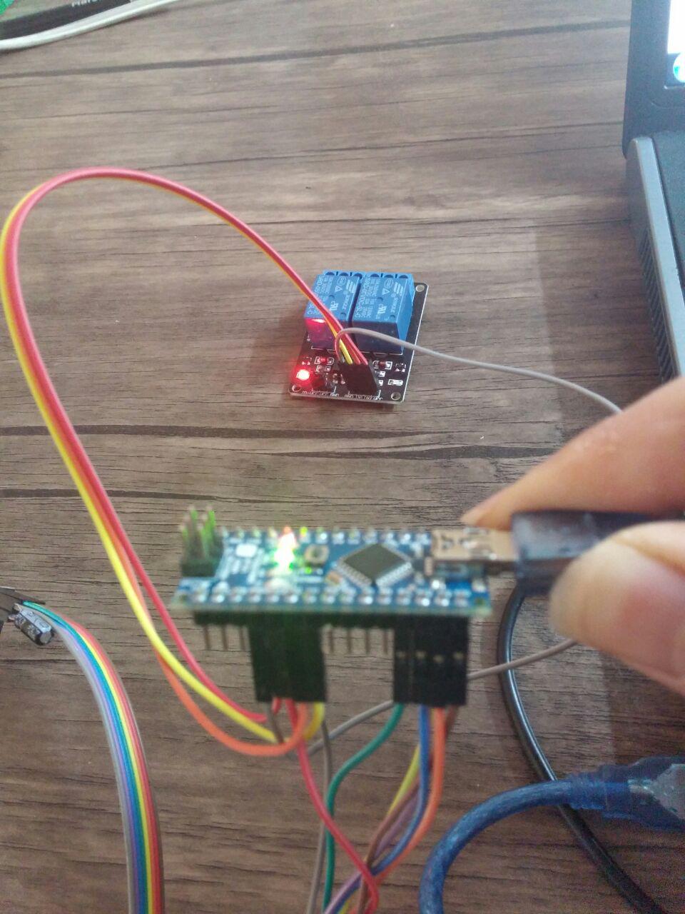
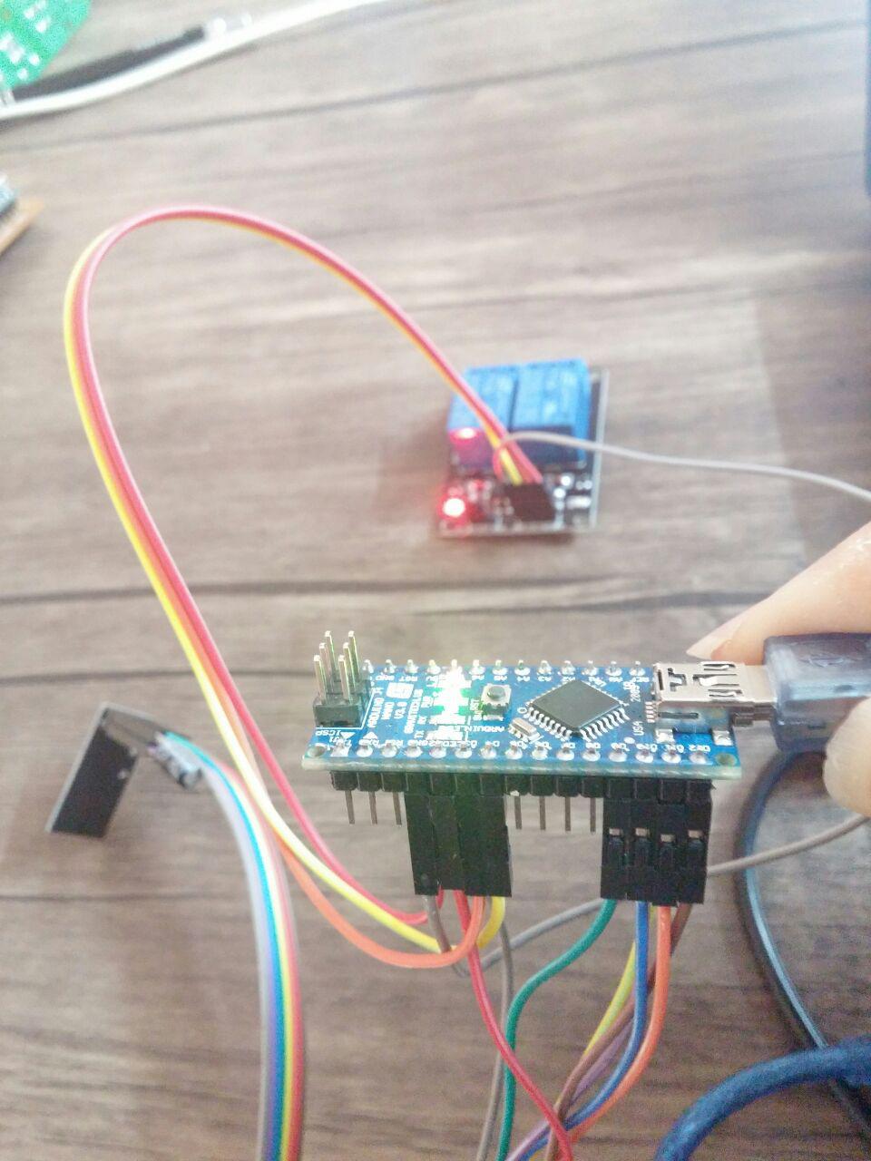
in1=pin3 , in2=pin4 . the pin 3 is not working , now in2 is working , but if i change pin3 and 4 in1 will working. also i change 2 line of program to and wiring in1=5 and in2=4 but now pin4 dont work ....
#define RELAY_1 4 // Arduino Digital I/O pin number for first relay (second on pin+1 etc)
#define NUMBER_OF_RELAYS 2 // Total number of attached relays
now -
Looks great - but taking steps here i want to know what happens in the serial log on your node when you send a on/off command from your controller?
-
@sundberg84 said:
Hi @Reza
The start logs looks ok. Does the relay/node log say anything when you send a command from your controller. Any info from your controller?
Did you define your pins for the relay? A long shot but someone wrote it worked when they changed from 3,4,5,6 to 4,5,6,7 for some reason.
In most cases though it seems to be a power problem. Try changin your power source and see what happens.What im most curous about at this point is to see the log from your relay when you send a on/off command for the two relays.
now I have a 2channel relay , i want test for 2channel but this is similar to 4channel .
in pics
in1=pin3 , in2=pin4 . the pin 3 is not working , now in2 is working , but if i change pin3 and 4 in1 will working. also i change 2 line of program to and wiring in1=5 and in2=4 but now pin4 dont work ....
#define RELAY_1 4 // Arduino Digital I/O pin number for first relay (second on pin+1 etc)
#define NUMBER_OF_RELAYS 2 // Total number of attached relays
now -
Looks great - but taking steps here i want to know what happens in the serial log on your node when you send a on/off command from your controller?
@sundberg84 said:
Looks great - but taking steps here i want to know what happens in the serial log on your node when you send a on/off command from your controller?
read: 0-0-2 s=2,c=1,t=2,pt=0,l=1,sg=0:1
send: 2-2-0-0 s=2,c=1,t=2,pt=0,l=1,sg=0,st=ok:1
Incoming change for sensor:2, New status: 1 -
@Reza we are kind of guessing in the dark right now. Can you post your sketch (as code, use the </> format button)
@AWI said:
@Reza we are kind of guessing in the dark right now. Can you post your sketch (as code, use the </> format button)
#include <MySigningNone.h> #include <MyTransportNRF24.h> #include <MyTransportRFM69.h> #include <MyHwATMega328.h> #include <MySensor.h> #include <SPI.h> #define RELAY_1 3 // Arduino Digital I/O pin number for first relay (second on pin+1 etc) #define NUMBER_OF_RELAYS 2 // Total number of attached relays #define RELAY_ON 1 // GPIO value to write to turn on attached relay #define RELAY_OFF 0 // GPIO value to write to turn off attached relay // NRFRF24L01 radio driver (set low transmit power by default) MyTransportNRF24 radio(RF24_CE_PIN, RF24_CS_PIN, RF24_PA_LEVEL_GW); //MyTransportRFM69 radio; // Message signing driver (none default) //MySigningNone signer; // Select AtMega328 hardware profile MyHwATMega328 hw; // Construct MySensors library MySensor gw(radio, hw); void setup() { // Initialize library and add callback for incoming messages gw.begin(incomingMessage, AUTO, true); // Send the sketch version information to the gateway and Controller gw.sendSketchInfo("Relay", "1.0"); // Fetch relay status for (int sensor=1, pin=RELAY_1; sensor<=NUMBER_OF_RELAYS;sensor++, pin++) { // Register all sensors to gw (they will be created as child devices) gw.present(sensor, S_LIGHT); // Then set relay pins in output mode pinMode(pin, OUTPUT); // Set relay to last known state (using eeprom storage) digitalWrite(pin, gw.loadState(sensor)?RELAY_ON:RELAY_OFF); } } void loop() { // Alway process incoming messages whenever possible gw.process(); } void incomingMessage(const MyMessage &message) { // We only expect one type of message from controller. But we better check anyway. if (message.type==V_LIGHT) { // Change relay state digitalWrite(message.sensor-1+RELAY_1, message.getBool()?RELAY_ON:RELAY_OFF); // Store state in eeprom gw.saveState(message.sensor, message.getBool()); // Write some debug info Serial.print("Incoming change for sensor:"); Serial.print(message.sensor); Serial.print(", New status: "); Serial.println(message.getBool()); } } -
@Reza - ok communication looks good. My vote will be on power.
I would try to power the relay separately and see what happens (not from Arduino). -
@Reza - ok communication looks good. My vote will be on power.
I would try to power the relay separately and see what happens (not from Arduino). -
@Reza From your images you are not - do you have another adaptor for the relay?
-
@Reza From your images you are not - do you have another adaptor for the relay?
-
Strange... im out of ideas at this point. Hardware failure?
Im not that good looking at the code, but I maybe someone else is. -
Strange... im out of ideas at this point. Hardware failure?
Im not that good looking at the code, but I maybe someone else is.@sundberg84 said:
Strange... im out of ideas at this point. Hardware failure?
Im not that good looking at the code, but I maybe someone else is.:( thank you
this is strange for me too . pin 3 dont working . but pin4 worked . also if i change cable of pin 3 and 4 other relay working and pin 3 dont work
I change 2 line :
#define RELAY_1 4
#define NUMBER_OF_RELAYS 2
but so pin 4 dont work and pin 5 working.... -
I'm a noob at electronics and arduinos and have a wild imagination :smiley:
I had a theory but was unsure, so I decided to test it first rather than cause more confusion.
I know this is a place of sharing, but more than once I caused more problems when trying to help.
I don't want to bring some stupid idea into the fold.
I'll report back.