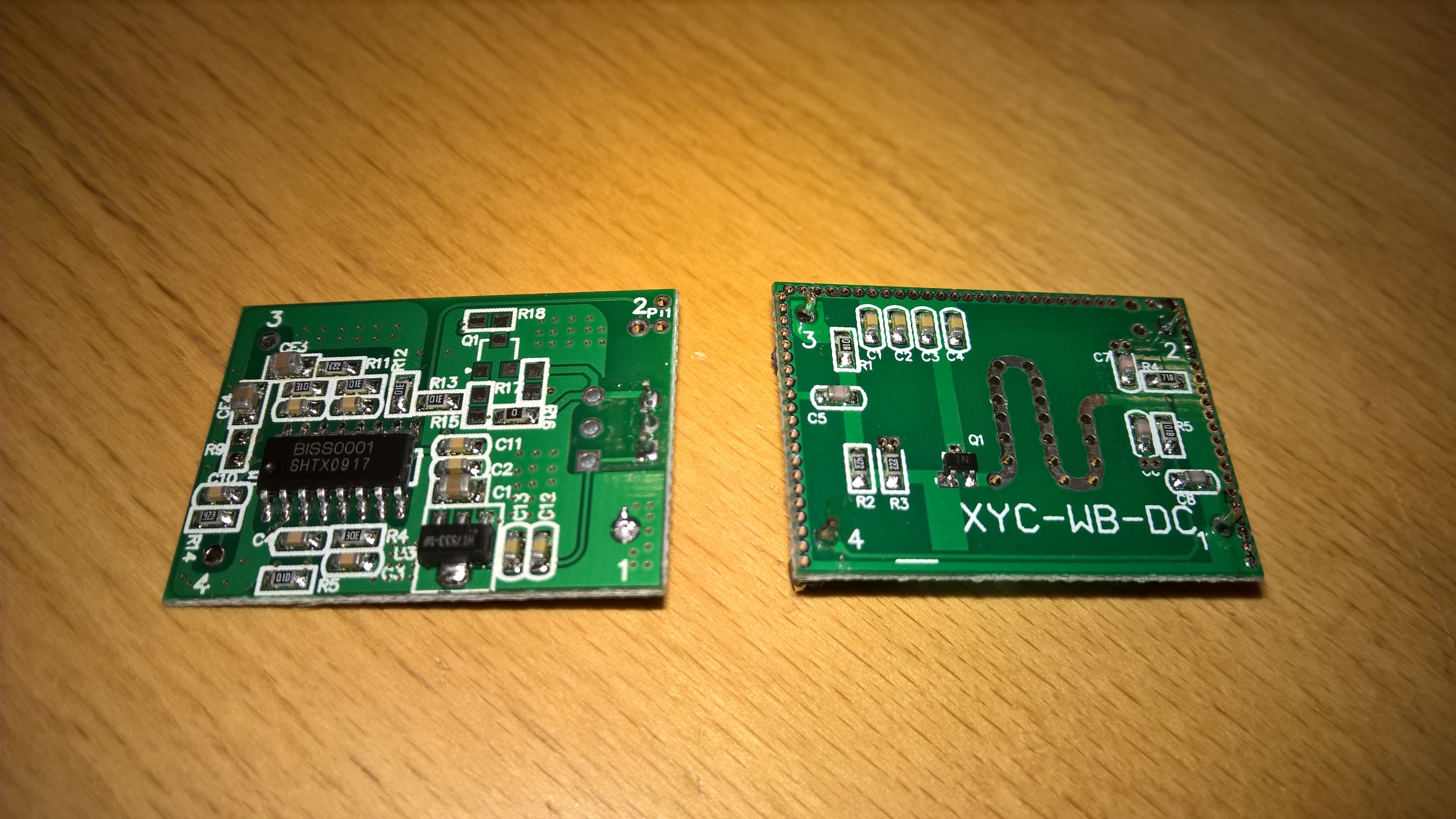
Microwave Radar Module as PIR replacement.
-
@drock1985, Didn't test it yet. I was playing with the other module I bought. Too bad that the other module only seems to work stable from 6V and up (I should have known it, as it was listed on ebay as 7-12v). I was just hoping that it would work at lower voltages. So I will probably stick with the first module for now.
@vil1driver, Yes, detection works through wall and door. I only tested it at a distance of about 5 meter with a brick indoor wall between me and the sensor. I also had to walk around before the sensor picked me up (just lifting my arm wasn't enough).
-
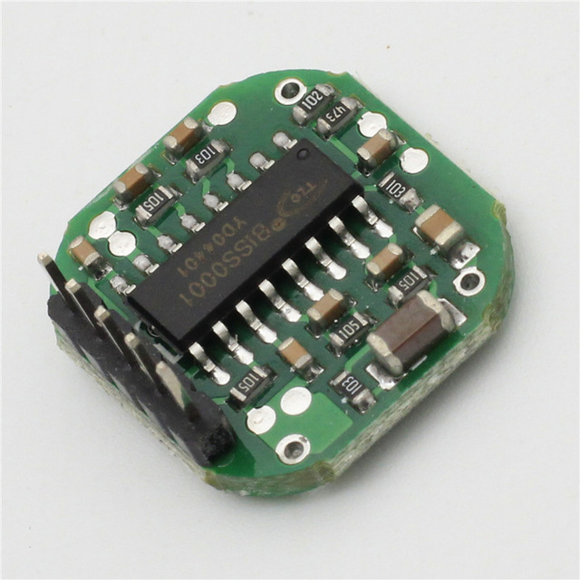
Seems like these modules are using the BISS0001 so it will probably not be possible to run them on a battery node because the BISS has a 3V minimum voltage demand. The current consumption is anyhow also a bit to high for battery application (3mA).
- Tomas
-
Seems like these modules are using the BISS0001 so it will probably not be possible to run them on a battery node because the BISS has a 3V minimum voltage demand. The current consumption is anyhow also a bit to high for battery application (3mA).
I've bought a couple of these and in many ways have been impressed.
My only issue is that I find them far too sensitive (e.g. Detecting movement through wallls)
Has anyone managed to reduce the sensitivity? -
@Luke-Corkill said:
I've bought a couple of these and in many ways have been impressed.
My only issue is that I find them far too sensitive (e.g. Detecting movement through wallls)
Has anyone managed to reduce the sensitivity?To reduce sensitivity workaround - Can you place them high and point them in an angle pointing downwards to ground? will this work?
-
There has been some chat about these modules over on Pete Scargill's site.
Seems that using some aluminium foil you can create a shield so there are at least directional.Here is the thread ( starting at the relevant comment)
http://tech.scargill.net/microwave-radar/#comment-16685
I have not tested this myself yet...
@gregl
Thanks for good link :-)
Yes offcurse I'm so sloooooow we need a proper waveguide or a hornet antenna, so ensure correct directionality ;-)This might not be needed, but a hint what could be done: http://hforsten.com/horn-antenna-for-radar.html
When my doppler radar arrives I will make a trial with a small tinbox I don't know about using alufoil is good for a long periode used outside
http://hackaday.com/2014/02/24/guest-post-try-radar-for-your-next-project/#jp-carousel-115578 -
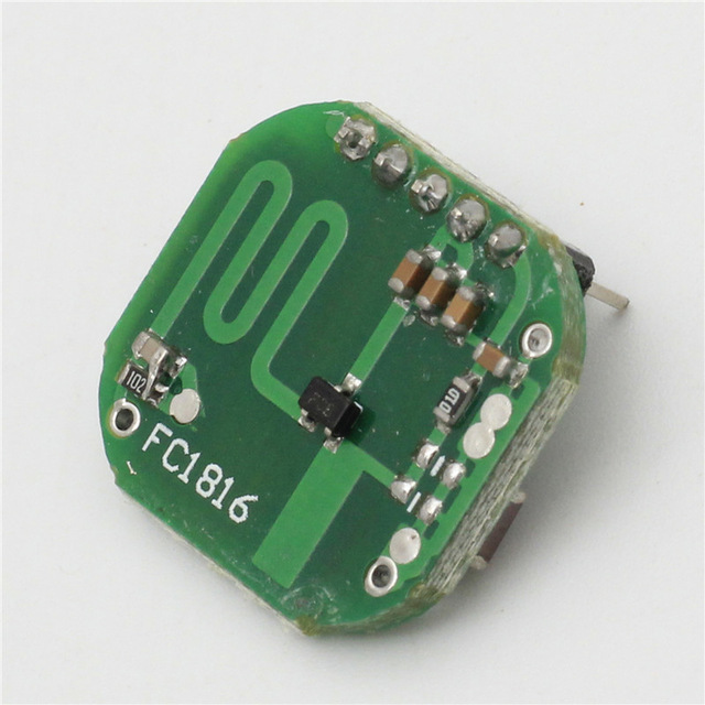
@Yveaux I did some extensive testing on the FC1816 module and I thought I might drop my experience:
http://electronics.stackexchange.com/questions/226031/pinout-of-microwave-motion-sensor-fc1816
In the end I used an 150ohm Series resistor + ~100µF cap behind this to power the FC1816. This eliminated much of the leftover noise. If this is not enough I presented a way to lower the module amplification. In the end I deactivated the biss-trigger output alltogether and grabbed the raw signal. Doing some manual processing:
- take 100 reads
- get the stddev (statistics library)
- high stddev = high fluctuation in values = movement
Take a look at my current working copy of my code for the FC1816:
Some notes:
I power the VCC of the FC1816 from some arduino pins. Thus I can deactivate the microwave sensor at will. This is still not recommended. If you visit the previous link you can see that the BISS has some kind of "warmup"-Period.
I use 3,3Volt to power the NRF24, the arduino and the FC1816 and suffered no strange consequences so far.
Get get some insight about the link quality of the NRF24 I made the function RF24_getObserverTX() accessible from user-space:
MySensors\drivers\RF24\RF24.cpp
uint8_t RF24_getObserveTX(void)
{
	return RF24_readByteRegister(OBSERVE_TX);
}
MySensors\drivers\RF24\RF24.h
uint8_t RF24_getObserveTX(void);The Idea behind the OBSERVE_TX register is that the lower byte presents the number of retrys the NRF24 used in the last send.
The upper 4 bits present the number of total failed packets. I suggest using (0x0F & RF24_getObserveTX()) to get a usable number 0-15 presenting the retry-count. Anything > 0 suggests a packetloss on your link. 15 most likely will mean you ran into an complete fail as the max number of retrys was exhausted.This number might be capped by
// ARD, auto retry count
#define RF24_ARC 15
from the RF24.h driver-file.
TO not run into compiling errors you might need:
http://arduiniana.org/libraries/streaming/
https://github.com/RobTillaart/Arduino/tree/master/libraries/StatisticMicrowaveRadarSensor.ino
#include <Streaming.h>
#include "Statistic.h"


/**
 * The MySensors Arduino library handles the wireless radio link and protocol
 * between your home built sensors/actuators and HA controller of choice.
 * The sensors forms a self healing radio network with optional repeaters. Each
 * repeater and gateway builds a routing tables in EEPROM which keeps track of the
 * network topology allowing messages to be routed to nodes.
 *
 * Created by Henrik Ekblad <henrik.ekblad@mysensors.org>
 * Copyright (C) 2013-2015 Sensnology AB
 * Full contributor list: https://github.com/mysensors/Arduino/graphs/contributors
 *
 * Documentation: http://www.mysensors.org
 * Support Forum: http://forum.mysensors.org
 *
 * This program is free software; you can redistribute it and/or
 * modify it under the terms of the GNU General Public License
 * version 2 as published by the Free Software Foundation.
 *
 *******************************
 *
 * REVISION HISTORY
 * Version 1.0 - Henrik EKblad
 *
 * DESCRIPTION
 * Example sketch showing how to measue light level using a LM393 photo-resistor
 * http://www.mysensors.org/build/light
 */

#define MY_NODE_ID 10
#define MY_BAUD_RATE 57600

// Enable debug prints to serial monitor
//#define MY_DEBUG

// Enable and select radio type attached
#define MY_RADIO_NRF24
//#define MY_RADIO_RFM69

#include <SPI.h>
#include <MySensors.h>

#define LIGHT_SENSOR_ANALOG_PIN A3
#define MICRO_SENSOR_ANALOG_PIN A1

unsigned long SLEEP_TIME = 1000; // Sleep time between reads (in milliseconds)

#define CHILD_ID_LIGHT 0
#define CHILD_ID_MICRO 0
#define TRIPPED_THRESHOLD 50

MyMessage msg_light(CHILD_ID_LIGHT, V_LIGHT_LEVEL); // 23
MyMessage msg_micro(CHILD_ID_MICRO, V_TRIPPED);     // 16
MyMessage msg_micro_debug(0,V_VAR1);   // 24
MyMessage msg_obstx_debug(0,V_VAR2);   // 25

void before()
{
  // LightSensor
  pinMode(A3,INPUT_PULLUP);
  pinMode(A2,OUTPUT);
  digitalWrite(A2,LOW);

  // Microwave
  pinMode(5,OUTPUT);        // VCC BISS0001
  digitalWrite(5,HIGH);

  pinMode(6,OUTPUT);        // Enabled
  digitalWrite(6,LOW);      // Enable

  pinMode(7,OUTPUT);        // GND
  digitalWrite(7,LOW);

  pinMode(8,OUTPUT);        // VCC Radar
  digitalWrite(8,HIGH);

  pinMode(A1,INPUT);        // PIR 2nd Amplification Stage

  // Other
}
void setup()
{

}
void presentation()  {
  // Send the sketch version information to the gateway and Controller
  sendSketchInfo("Microwave+Light", "1.0");

  // Register all sensors to gateway (they will be created as child devices)
  // https://www.mysensors.org/download/serial_api_20#sensor-type
  present(CHILD_ID_LIGHT, S_LIGHT_LEVEL);
  present(CHILD_ID_MICRO, S_MOTION);
  //present(0, S_ARDUINO_NODE);

}

void loop()
{
  // Report VCC
  static long vcc = readVcc();
  static int vccpercent = map(vcc,1800,3280,0,100);
  sendBatteryLevel(max(min(vccpercent,100),0),false);
  Serial << "| vcc: ";
  p(F("%4d"),vcc);
  Serial << " ";
  // Required for ack
  //wait(100);

  // Report LightLevel
  analogRead(LIGHT_SENSOR_ANALOG_PIN);
  int lightLevel_raw = analogRead(LIGHT_SENSOR_ANALOG_PIN);
  int lightLevel = (1023-lightLevel_raw)/10.23; // as of 1023 !!
  Serial << "| light_raw: ";
  p(F("%4d"),lightLevel_raw);
  Serial << " ";
  Serial << "| light: ";
  p(F("%3d"),lightLevel);
  Serial << " ";
  send(msg_light.set(lightLevel),false);

  // Report WirelessLink Information
  Serial << "| observe_tx: ";
  uint8_t obstx = RF24_getObserveTX();
  p(F("%X"),obstx);
  Serial << " ";
  send(msg_obstx_debug.set(0x0F&obstx),false);

  // Report Microwave
  Statistic mw_s;
  mw_s.clear();

  delay(90);
  analogRead(MICRO_SENSOR_ANALOG_PIN);
  delay(10);
  for(int i = 0; i < 1000; i++)
  {
    mw_s.add(analogRead(MICRO_SENSOR_ANALOG_PIN));
    delay(1);
  }
  Serial << "| mw_raw: ";
  int stddev = mw_s.pop_stdev();
  p(F("%4d"),stddev);
  Serial << " ";

  Serial << "| mw_min: ";
  int minimum = mw_s.minimum();
  p(F("%4d"),minimum);
  Serial << " ";

  Serial << "| mw_max: ";
  int maximum = mw_s.maximum();
  p(F("%4d"),maximum);
  Serial << " ";

  Serial << "| mw: " << (stddev > TRIPPED_THRESHOLD ? "1" : "0") << " ";
  send(msg_micro_debug.set(stddev),false);
  while(!send(msg_micro.set(stddev > TRIPPED_THRESHOLD ? "1" : "0"),true))
  {
    wait(10);
  }

  if(isTransportOK())
    wait(100);
  else
    wait(1000);
  Serial << endl;
  //mysleep(500);

}
// https://forum.mysensors.org/topic/3463/m_ack_variable-or-m_set_variable/2
void receive(const MyMessage &message) {
  if (message.isAck()) {
      Serial.print("| GW ack");
      }
}
Helper.ino
long readVcc() { // Read 1.1V reference against AVcc // set the reference to Vcc and the measurement to the internal 1.1V reference #if defined(__AVR_ATmega32U4__) || defined(__AVR_ATmega1280__) || defined(__AVR_ATmega2560__) ADMUX = _BV(REFS0) | _BV(MUX4) | _BV(MUX3) | _BV(MUX2) | _BV(MUX1); #elif defined (__AVR_ATtiny24__) || defined(__AVR_ATtiny44__) || defined(__AVR_ATtiny84__) ADMUX = _BV(MUX5) | _BV(MUX0); #elif defined (__AVR_ATtiny25__) || defined(__AVR_ATtiny45__) || defined(__AVR_ATtiny85__) ADMUX = _BV(MUX3) | _BV(MUX2); #else ADMUX = _BV(REFS0) | _BV(MUX3) | _BV(MUX2) | _BV(MUX1); #endif delay(2); // Wait for Vref to settle ADCSRA |= _BV(ADSC); // Start conversion while (bit_is_set(ADCSRA,ADSC)); // measuring uint8_t low = ADCL; // must read ADCL first - it then locks ADCH uint8_t high = ADCH; // unlocks both long result = (high<<8) | low; result = 1125300L / result; // Calculate Vcc (in mV); 1125300 = 1.1*1023*1000 //result *= 1.0637; return result; // Vcc in millivolts } #include <stdarg.h> void p(const __FlashStringHelper *fmt, ... ){ char buf[128]; // resulting string limited to 128 chars va_list args; va_start (args, fmt); #ifdef __AVR__ vsnprintf_P(buf, sizeof(buf), (const char *)fmt, args); // progmem for AVR #else vsnprintf(buf, sizeof(buf), (const char *)fmt, args); // for the rest of the world #endif va_end(args); Serial.print(buf); } void mysleep(int SLEEP_TIME) { if(isTransportOK()){ Serial << "| wait "; wait(25); Serial << "| zZz > "; sleep(SLEEP_TIME); Serial << "| < zZz " << endl; } else { wait(1000); } } -
@Yveaux I did some extensive testing on the FC1816 module and I thought I might drop my experience:
http://electronics.stackexchange.com/questions/226031/pinout-of-microwave-motion-sensor-fc1816
In the end I used an 150ohm Series resistor + ~100µF cap behind this to power the FC1816. This eliminated much of the leftover noise. If this is not enough I presented a way to lower the module amplification. In the end I deactivated the biss-trigger output alltogether and grabbed the raw signal. Doing some manual processing:
- take 100 reads
- get the stddev (statistics library)
- high stddev = high fluctuation in values = movement
Take a look at my current working copy of my code for the FC1816:
Some notes:
I power the VCC of the FC1816 from some arduino pins. Thus I can deactivate the microwave sensor at will. This is still not recommended. If you visit the previous link you can see that the BISS has some kind of "warmup"-Period.
I use 3,3Volt to power the NRF24, the arduino and the FC1816 and suffered no strange consequences so far.
Get get some insight about the link quality of the NRF24 I made the function RF24_getObserverTX() accessible from user-space:
MySensors\drivers\RF24\RF24.cpp
uint8_t RF24_getObserveTX(void)
{
	return RF24_readByteRegister(OBSERVE_TX);
}
MySensors\drivers\RF24\RF24.h
uint8_t RF24_getObserveTX(void);The Idea behind the OBSERVE_TX register is that the lower byte presents the number of retrys the NRF24 used in the last send.
The upper 4 bits present the number of total failed packets. I suggest using (0x0F & RF24_getObserveTX()) to get a usable number 0-15 presenting the retry-count. Anything > 0 suggests a packetloss on your link. 15 most likely will mean you ran into an complete fail as the max number of retrys was exhausted.This number might be capped by
// ARD, auto retry count
#define RF24_ARC 15
from the RF24.h driver-file.
TO not run into compiling errors you might need:
http://arduiniana.org/libraries/streaming/
https://github.com/RobTillaart/Arduino/tree/master/libraries/StatisticMicrowaveRadarSensor.ino
#include <Streaming.h>
#include "Statistic.h"


/**
 * The MySensors Arduino library handles the wireless radio link and protocol
 * between your home built sensors/actuators and HA controller of choice.
 * The sensors forms a self healing radio network with optional repeaters. Each
 * repeater and gateway builds a routing tables in EEPROM which keeps track of the
 * network topology allowing messages to be routed to nodes.
 *
 * Created by Henrik Ekblad <henrik.ekblad@mysensors.org>
 * Copyright (C) 2013-2015 Sensnology AB
 * Full contributor list: https://github.com/mysensors/Arduino/graphs/contributors
 *
 * Documentation: http://www.mysensors.org
 * Support Forum: http://forum.mysensors.org
 *
 * This program is free software; you can redistribute it and/or
 * modify it under the terms of the GNU General Public License
 * version 2 as published by the Free Software Foundation.
 *
 *******************************
 *
 * REVISION HISTORY
 * Version 1.0 - Henrik EKblad
 *
 * DESCRIPTION
 * Example sketch showing how to measue light level using a LM393 photo-resistor
 * http://www.mysensors.org/build/light
 */

#define MY_NODE_ID 10
#define MY_BAUD_RATE 57600

// Enable debug prints to serial monitor
//#define MY_DEBUG

// Enable and select radio type attached
#define MY_RADIO_NRF24
//#define MY_RADIO_RFM69

#include <SPI.h>
#include <MySensors.h>

#define LIGHT_SENSOR_ANALOG_PIN A3
#define MICRO_SENSOR_ANALOG_PIN A1

unsigned long SLEEP_TIME = 1000; // Sleep time between reads (in milliseconds)

#define CHILD_ID_LIGHT 0
#define CHILD_ID_MICRO 0
#define TRIPPED_THRESHOLD 50

MyMessage msg_light(CHILD_ID_LIGHT, V_LIGHT_LEVEL); // 23
MyMessage msg_micro(CHILD_ID_MICRO, V_TRIPPED);     // 16
MyMessage msg_micro_debug(0,V_VAR1);   // 24
MyMessage msg_obstx_debug(0,V_VAR2);   // 25

void before()
{
  // LightSensor
  pinMode(A3,INPUT_PULLUP);
  pinMode(A2,OUTPUT);
  digitalWrite(A2,LOW);

  // Microwave
  pinMode(5,OUTPUT);        // VCC BISS0001
  digitalWrite(5,HIGH);

  pinMode(6,OUTPUT);        // Enabled
  digitalWrite(6,LOW);      // Enable

  pinMode(7,OUTPUT);        // GND
  digitalWrite(7,LOW);

  pinMode(8,OUTPUT);        // VCC Radar
  digitalWrite(8,HIGH);

  pinMode(A1,INPUT);        // PIR 2nd Amplification Stage

  // Other
}
void setup()
{

}
void presentation()  {
  // Send the sketch version information to the gateway and Controller
  sendSketchInfo("Microwave+Light", "1.0");

  // Register all sensors to gateway (they will be created as child devices)
  // https://www.mysensors.org/download/serial_api_20#sensor-type
  present(CHILD_ID_LIGHT, S_LIGHT_LEVEL);
  present(CHILD_ID_MICRO, S_MOTION);
  //present(0, S_ARDUINO_NODE);

}

void loop()
{
  // Report VCC
  static long vcc = readVcc();
  static int vccpercent = map(vcc,1800,3280,0,100);
  sendBatteryLevel(max(min(vccpercent,100),0),false);
  Serial << "| vcc: ";
  p(F("%4d"),vcc);
  Serial << " ";
  // Required for ack
  //wait(100);

  // Report LightLevel
  analogRead(LIGHT_SENSOR_ANALOG_PIN);
  int lightLevel_raw = analogRead(LIGHT_SENSOR_ANALOG_PIN);
  int lightLevel = (1023-lightLevel_raw)/10.23; // as of 1023 !!
  Serial << "| light_raw: ";
  p(F("%4d"),lightLevel_raw);
  Serial << " ";
  Serial << "| light: ";
  p(F("%3d"),lightLevel);
  Serial << " ";
  send(msg_light.set(lightLevel),false);

  // Report WirelessLink Information
  Serial << "| observe_tx: ";
  uint8_t obstx = RF24_getObserveTX();
  p(F("%X"),obstx);
  Serial << " ";
  send(msg_obstx_debug.set(0x0F&obstx),false);

  // Report Microwave
  Statistic mw_s;
  mw_s.clear();

  delay(90);
  analogRead(MICRO_SENSOR_ANALOG_PIN);
  delay(10);
  for(int i = 0; i < 1000; i++)
  {
    mw_s.add(analogRead(MICRO_SENSOR_ANALOG_PIN));
    delay(1);
  }
  Serial << "| mw_raw: ";
  int stddev = mw_s.pop_stdev();
  p(F("%4d"),stddev);
  Serial << " ";

  Serial << "| mw_min: ";
  int minimum = mw_s.minimum();
  p(F("%4d"),minimum);
  Serial << " ";

  Serial << "| mw_max: ";
  int maximum = mw_s.maximum();
  p(F("%4d"),maximum);
  Serial << " ";

  Serial << "| mw: " << (stddev > TRIPPED_THRESHOLD ? "1" : "0") << " ";
  send(msg_micro_debug.set(stddev),false);
  while(!send(msg_micro.set(stddev > TRIPPED_THRESHOLD ? "1" : "0"),true))
  {
    wait(10);
  }

  if(isTransportOK())
    wait(100);
  else
    wait(1000);
  Serial << endl;
  //mysleep(500);

}
// https://forum.mysensors.org/topic/3463/m_ack_variable-or-m_set_variable/2
void receive(const MyMessage &message) {
  if (message.isAck()) {
      Serial.print("| GW ack");
      }
}
Helper.ino
long readVcc() { // Read 1.1V reference against AVcc // set the reference to Vcc and the measurement to the internal 1.1V reference #if defined(__AVR_ATmega32U4__) || defined(__AVR_ATmega1280__) || defined(__AVR_ATmega2560__) ADMUX = _BV(REFS0) | _BV(MUX4) | _BV(MUX3) | _BV(MUX2) | _BV(MUX1); #elif defined (__AVR_ATtiny24__) || defined(__AVR_ATtiny44__) || defined(__AVR_ATtiny84__) ADMUX = _BV(MUX5) | _BV(MUX0); #elif defined (__AVR_ATtiny25__) || defined(__AVR_ATtiny45__) || defined(__AVR_ATtiny85__) ADMUX = _BV(MUX3) | _BV(MUX2); #else ADMUX = _BV(REFS0) | _BV(MUX3) | _BV(MUX2) | _BV(MUX1); #endif delay(2); // Wait for Vref to settle ADCSRA |= _BV(ADSC); // Start conversion while (bit_is_set(ADCSRA,ADSC)); // measuring uint8_t low = ADCL; // must read ADCL first - it then locks ADCH uint8_t high = ADCH; // unlocks both long result = (high<<8) | low; result = 1125300L / result; // Calculate Vcc (in mV); 1125300 = 1.1*1023*1000 //result *= 1.0637; return result; // Vcc in millivolts } #include <stdarg.h> void p(const __FlashStringHelper *fmt, ... ){ char buf[128]; // resulting string limited to 128 chars va_list args; va_start (args, fmt); #ifdef __AVR__ vsnprintf_P(buf, sizeof(buf), (const char *)fmt, args); // progmem for AVR #else vsnprintf(buf, sizeof(buf), (const char *)fmt, args); // for the rest of the world #endif va_end(args); Serial.print(buf); } void mysleep(int SLEEP_TIME) { if(isTransportOK()){ Serial << "| wait "; wait(25); Serial << "| zZz > "; sleep(SLEEP_TIME); Serial << "| < zZz " << endl; } else { wait(1000); } }@cimba007 wow, you did some serious research there! (I see you make good use of the arduino plot function)
I'll certainly come back to your research once I start with this sensor (so much to choose from...)
Any ideas about current consumption? Is this a viable alternative to battery powered pir sensors?http://yveaux.blogspot.nl
-
@cimba007 wow, you did some serious research there! (I see you make good use of the arduino plot function)
I'll certainly come back to your research once I start with this sensor (so much to choose from...)
Any ideas about current consumption? Is this a viable alternative to battery powered pir sensors?@Yveaux From my oppinion the radar modules are not suited for battery usage. Their drain something like 3-5mA and are not easy to put to sleep. Remember the warm-up period of the BISS. It seems to be like 10-15seconds.
The plots are from another sketch, not the one I posted but using them is pretty straight forward.
In my sketch have a look at these parts:
  Serial << "| mw_min: ";
  int minimum = mw_s.minimum();
  p(F("%4d"),minimum);
  Serial << " ";
To use the arduino plotting all you ahve to do is send a string like this:
0,10,534,123 .. whatever .. beware that no other serial output should happen if you want to use the arduino build-in plotting. Using the streaming library ( http://arduiniana.org/libraries/streaming/ ) it all boils down to a single line:
Serial << mw_s.minimum() << "," << mw_s.maximum() << "," << mw_s.pop_stdev() << endl;In addition to the power consumption my approach requires sampling the analog input for a whole second .. or the more the better.
This might be improved if you can prevent the FC1816 from retriggering itself. I had some serious problems as during the "inhibitor" period the analogOutput from the 2nd amplification stage was quite high often instantly retrigger the biss-output after the inhibition period ended.
One solution might be this:
Try this if you want to look down this approch:
- Power the FC1816 VCC and UDP through an RC-Section (100Ohm Resistor and after that (on the side of the FC1816) an capacitory ~100-220µF)
- Replace amplification resistor from 105 to eg. 154 (lowering the amplification)
To find the best value I used an variable resistor parallel to the 105-Ohms SMD-Resistor
But .. don't forget the benefits of *he microwave sensor. You can mount it straight to a door and it would detect persons in front of the door without them noticing. For this reason I try to build an "Alarm-node" that can be hidden inside the house. Later I might improve the FC1816 with some aluminium foil for shielding as suggested earlier.
I would suggest using an PIR if you need a battery powered node. Have a look at ( http://kavacky.lv/bypassing-sen-08630-pir-motion-sensors-voltage-regulator-to-work-with-3-3-v ). Some PIRs have a Regulator which might not be suited if you are running on battery using 3,3Volt.
-
@Yveaux From my oppinion the radar modules are not suited for battery usage. Their drain something like 3-5mA and are not easy to put to sleep. Remember the warm-up period of the BISS. It seems to be like 10-15seconds.
The plots are from another sketch, not the one I posted but using them is pretty straight forward.
In my sketch have a look at these parts:
  Serial << "| mw_min: ";
  int minimum = mw_s.minimum();
  p(F("%4d"),minimum);
  Serial << " ";
To use the arduino plotting all you ahve to do is send a string like this:
0,10,534,123 .. whatever .. beware that no other serial output should happen if you want to use the arduino build-in plotting. Using the streaming library ( http://arduiniana.org/libraries/streaming/ ) it all boils down to a single line:
Serial << mw_s.minimum() << "," << mw_s.maximum() << "," << mw_s.pop_stdev() << endl;In addition to the power consumption my approach requires sampling the analog input for a whole second .. or the more the better.
This might be improved if you can prevent the FC1816 from retriggering itself. I had some serious problems as during the "inhibitor" period the analogOutput from the 2nd amplification stage was quite high often instantly retrigger the biss-output after the inhibition period ended.
One solution might be this:
Try this if you want to look down this approch:
- Power the FC1816 VCC and UDP through an RC-Section (100Ohm Resistor and after that (on the side of the FC1816) an capacitory ~100-220µF)
- Replace amplification resistor from 105 to eg. 154 (lowering the amplification)
To find the best value I used an variable resistor parallel to the 105-Ohms SMD-Resistor
But .. don't forget the benefits of *he microwave sensor. You can mount it straight to a door and it would detect persons in front of the door without them noticing. For this reason I try to build an "Alarm-node" that can be hidden inside the house. Later I might improve the FC1816 with some aluminium foil for shielding as suggested earlier.
I would suggest using an PIR if you need a battery powered node. Have a look at ( http://kavacky.lv/bypassing-sen-08630-pir-motion-sensors-voltage-regulator-to-work-with-3-3-v ). Some PIRs have a Regulator which might not be suited if you are running on battery using 3,3Volt.
-
All things from my previous post regarding the wiring are still needed:
Here is a stripped down example on how to use the FC1816 Microwave Sensor. You need the following library:
https://github.com/RobTillaart/Arduino/tree/master/libraries/Statistic
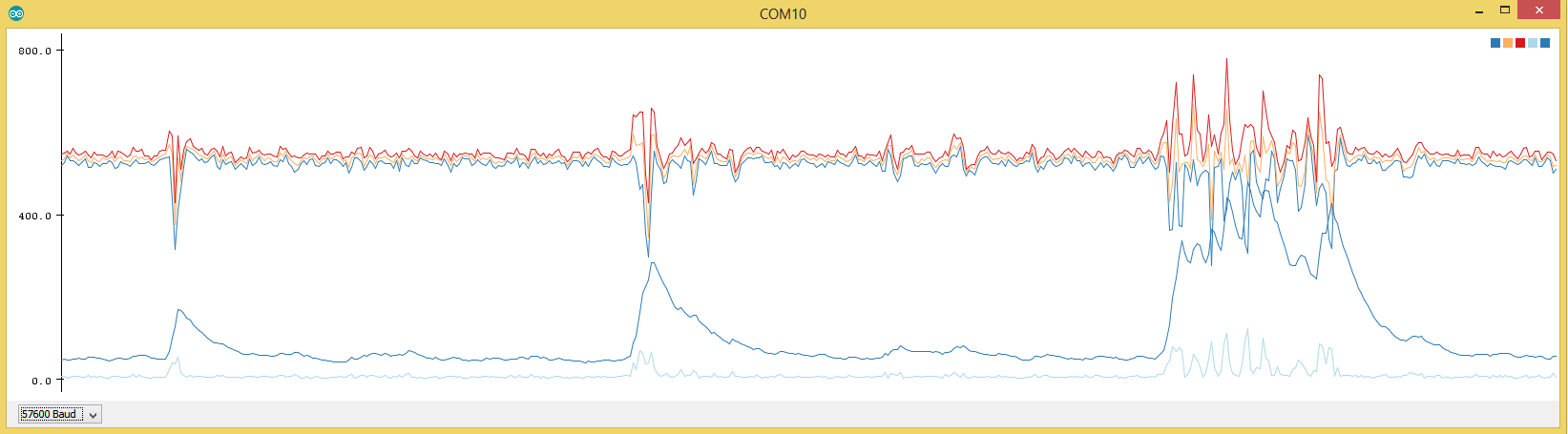
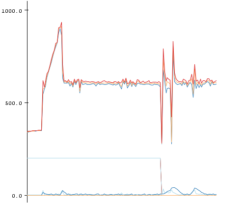
#include "Statistic.h"

#define MICRO_SENSOR_ANALOG_PIN A1

void setup()
{

  Serial.begin(57600);
  Serial.print("begin");

  // Microwave
  pinMode(5,OUTPUT);        // VCC BISS0001
  digitalWrite(5,HIGH);

  pinMode(6,OUTPUT);        // Enabled
  digitalWrite(6,LOW);      // DISABLE PLEASE!

  pinMode(7,OUTPUT);        // GND
  digitalWrite(7,LOW);

  pinMode(A1,INPUT);        // PIR 2nd amplification stage

  pinMode(A0,OUTPUT);       // UPD microwave generator
  digitalWrite(A0,HIGH);

}

void loop()
{
  // Report Microwave
  static Statistic mw_s;
  static uint16_t stdev_sum = 0;
  //mw_s.clear();

  //digitalWrite(8,HIGH);
  //delay(100);
  analogRead(MICRO_SENSOR_ANALOG_PIN);
  uint16_t reading;
  for(int i = 0; i < 200; i++)
  {
    reading = analogRead(MICRO_SENSOR_ANALOG_PIN);
    mw_s.add(reading);
    //Serial.println(reading);
    //Serial.flush();
    //delay(50);
    //LowPower.powerDown(SLEEP_60MS, ADC_ON, BOD_OFF);
    //delay(1);
  }
  Serial.print(mw_s.minimum());   Serial.print(",");
  Serial.print(mw_s.average());   Serial.print(",");
  Serial.print(mw_s.maximum());   Serial.print(",");
  Serial.print(mw_s.pop_stdev()); Serial.print(",");
  stdev_sum += mw_s.pop_stdev();
  Serial.print(stdev_sum); //Serial.print(",");
  Serial.println();
  stdev_sum *= 0.9;
  mw_s.clear();
}
I just had the idea to sum up the std-dev and decrease it by 10% every round. Thus the code is less prone to peaks.
stdev_sum is the lower dark blue line which can now be much easier compared to a threshold.
Some measurement with my µCurrent-Gold:
Unmodified code as above, power LED removed from ProMini @ 8Mhz internal osci with LDO desoldered
4,8mAI tried to put the FC1816 into sleep by disable the power to the Microwave generator but this doesn't work.
I modified the fuses for 8Mhz with 0ms wakeup delay for stabelizing the oscillator. No risk no phun ;-)The most practical solution I got to replace a PIR (still nothing as close as a PIR ;-ö)
1530µA
with this code:
Note that the radar generator just can't be disable as it needs 10-15seconds to stabelize after power up
#include <LowPower.h> #include "Statistic.h" #define MICRO_SENSOR_ANALOG_PIN A1 void setup() { Serial.begin(57600); Serial.print("begin"); // Microwave pinMode(5,OUTPUT); // VCC BISS0001 digitalWrite(5,HIGH); pinMode(6,OUTPUT); // Enabled digitalWrite(6,LOW); // DISABLE PLEASE! pinMode(7,OUTPUT); // GND digitalWrite(7,LOW); pinMode(A1,INPUT); // PIR 2nd amplification stage pinMode(A0,OUTPUT); // UPD microwave generator digitalWrite(A0,HIGH); } void loop() { // Report Microwave static Statistic mw_s; static uint16_t stdev_sum = 0; //mw_s.clear(); //delay(100); analogRead(MICRO_SENSOR_ANALOG_PIN); uint16_t reading; for(int i = 0; i < 10; i++) { LowPower.powerDown(SLEEP_15Ms, ADC_ON, BOD_OFF); reading = analogRead(MICRO_SENSOR_ANALOG_PIN); mw_s.add(reading); //Serial.println(reading); //Serial.flush(); //delay(50); LowPower.powerDown(SLEEP_15Ms, ADC_ON, BOD_OFF); //delay(1); } Serial.print(mw_s.minimum()); Serial.print(","); Serial.print(mw_s.average()); Serial.print(","); Serial.print(mw_s.maximum()); Serial.print(","); Serial.print(mw_s.pop_stdev()); Serial.print(","); stdev_sum += mw_s.pop_stdev(); Serial.print(stdev_sum); //Serial.print(","); Serial.println(); Serial.flush(); stdev_sum *= 0.9; mw_s.clear(); } -
All things from my previous post regarding the wiring are still needed:
Here is a stripped down example on how to use the FC1816 Microwave Sensor. You need the following library:
https://github.com/RobTillaart/Arduino/tree/master/libraries/Statistic
#include "Statistic.h"

#define MICRO_SENSOR_ANALOG_PIN A1

void setup()
{

  Serial.begin(57600);
  Serial.print("begin");

  // Microwave
  pinMode(5,OUTPUT);        // VCC BISS0001
  digitalWrite(5,HIGH);

  pinMode(6,OUTPUT);        // Enabled
  digitalWrite(6,LOW);      // DISABLE PLEASE!

  pinMode(7,OUTPUT);        // GND
  digitalWrite(7,LOW);

  pinMode(A1,INPUT);        // PIR 2nd amplification stage

  pinMode(A0,OUTPUT);       // UPD microwave generator
  digitalWrite(A0,HIGH);

}

void loop()
{
  // Report Microwave
  static Statistic mw_s;
  static uint16_t stdev_sum = 0;
  //mw_s.clear();

  //digitalWrite(8,HIGH);
  //delay(100);
  analogRead(MICRO_SENSOR_ANALOG_PIN);
  uint16_t reading;
  for(int i = 0; i < 200; i++)
  {
    reading = analogRead(MICRO_SENSOR_ANALOG_PIN);
    mw_s.add(reading);
    //Serial.println(reading);
    //Serial.flush();
    //delay(50);
    //LowPower.powerDown(SLEEP_60MS, ADC_ON, BOD_OFF);
    //delay(1);
  }
  Serial.print(mw_s.minimum());   Serial.print(",");
  Serial.print(mw_s.average());   Serial.print(",");
  Serial.print(mw_s.maximum());   Serial.print(",");
  Serial.print(mw_s.pop_stdev()); Serial.print(",");
  stdev_sum += mw_s.pop_stdev();
  Serial.print(stdev_sum); //Serial.print(",");
  Serial.println();
  stdev_sum *= 0.9;
  mw_s.clear();
}
I just had the idea to sum up the std-dev and decrease it by 10% every round. Thus the code is less prone to peaks.
stdev_sum is the lower dark blue line which can now be much easier compared to a threshold.
Some measurement with my µCurrent-Gold:
Unmodified code as above, power LED removed from ProMini @ 8Mhz internal osci with LDO desoldered
4,8mAI tried to put the FC1816 into sleep by disable the power to the Microwave generator but this doesn't work.
I modified the fuses for 8Mhz with 0ms wakeup delay for stabelizing the oscillator. No risk no phun ;-)The most practical solution I got to replace a PIR (still nothing as close as a PIR ;-ö)
1530µA
with this code:
Note that the radar generator just can't be disable as it needs 10-15seconds to stabelize after power up
#include <LowPower.h> #include "Statistic.h" #define MICRO_SENSOR_ANALOG_PIN A1 void setup() { Serial.begin(57600); Serial.print("begin"); // Microwave pinMode(5,OUTPUT); // VCC BISS0001 digitalWrite(5,HIGH); pinMode(6,OUTPUT); // Enabled digitalWrite(6,LOW); // DISABLE PLEASE! pinMode(7,OUTPUT); // GND digitalWrite(7,LOW); pinMode(A1,INPUT); // PIR 2nd amplification stage pinMode(A0,OUTPUT); // UPD microwave generator digitalWrite(A0,HIGH); } void loop() { // Report Microwave static Statistic mw_s; static uint16_t stdev_sum = 0; //mw_s.clear(); //delay(100); analogRead(MICRO_SENSOR_ANALOG_PIN); uint16_t reading; for(int i = 0; i < 10; i++) { LowPower.powerDown(SLEEP_15Ms, ADC_ON, BOD_OFF); reading = analogRead(MICRO_SENSOR_ANALOG_PIN); mw_s.add(reading); //Serial.println(reading); //Serial.flush(); //delay(50); LowPower.powerDown(SLEEP_15Ms, ADC_ON, BOD_OFF); //delay(1); } Serial.print(mw_s.minimum()); Serial.print(","); Serial.print(mw_s.average()); Serial.print(","); Serial.print(mw_s.maximum()); Serial.print(","); Serial.print(mw_s.pop_stdev()); Serial.print(","); stdev_sum += mw_s.pop_stdev(); Serial.print(stdev_sum); //Serial.print(","); Serial.println(); Serial.flush(); stdev_sum *= 0.9; mw_s.clear(); } -
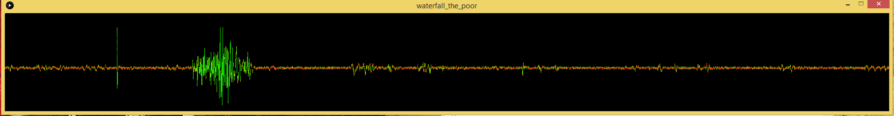
After a few more days of testing I noticed these ugly "PEAKS" from my FC1816 readings. I added lots of capacitors and RC and LC sections but still .. nasty little peaks (left side in the beginning)
In my previous post replace this line:
stdev_sum += mw_s.pop_stdev();with this:
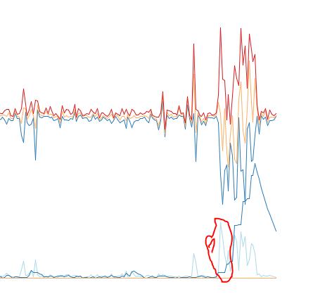
  // Ignore the first 3 peaks within short succession
  // Real movement should mean there are more peaks/activity over a long time
  static uint8_t peakcount = 0;
  if(mw_s.pop_stdev() > 30 && peakcount < 3)
  {
    peakcount++;
  }
  else
  {
    stdev_sum += mw_s.pop_stdev();
    stdev_sum *= 0.92; //
    if (stdev_sum >= 7)
      stdev_sum -= 7; // Default background noise
    if (stdev_sum > 512)
      stdev_sum = 512;

    if(peakcount > 0)
      peakcount--;
  }
With this code the first 3 peaks are essentially removed .. if there is really some movement it should last for a few seconds and would still be detected.
I have invested like 10-20hours into testing and debugging the FC1816 and I can say .. this thing is .. peculiar ..
I hate it cause of the spikes, the amplification which has to be manually altered with a pot .. but at the same time I love it ..
I can detect my foot beckoning 2-3meters apart in my bed :D
An example of the code snipped in action:
Here you can see the big spikes in the beginning completely ignored (1)
-
After a few more days of testing I noticed these ugly "PEAKS" from my FC1816 readings. I added lots of capacitors and RC and LC sections but still .. nasty little peaks (left side in the beginning)
In my previous post replace this line:
stdev_sum += mw_s.pop_stdev();with this:
  // Ignore the first 3 peaks within short succession
  // Real movement should mean there are more peaks/activity over a long time
  static uint8_t peakcount = 0;
  if(mw_s.pop_stdev() > 30 && peakcount < 3)
  {
    peakcount++;
  }
  else
  {
    stdev_sum += mw_s.pop_stdev();
    stdev_sum *= 0.92; //
    if (stdev_sum >= 7)
      stdev_sum -= 7; // Default background noise
    if (stdev_sum > 512)
      stdev_sum = 512;

    if(peakcount > 0)
      peakcount--;
  }
With this code the first 3 peaks are essentially removed .. if there is really some movement it should last for a few seconds and would still be detected.
I have invested like 10-20hours into testing and debugging the FC1816 and I can say .. this thing is .. peculiar ..
I hate it cause of the spikes, the amplification which has to be manually altered with a pot .. but at the same time I love it ..
I can detect my foot beckoning 2-3meters apart in my bed :D
An example of the code snipped in action:
Here you can see the big spikes in the beginning completely ignored (1)
-
Currently I don't plan to make a library .. a library implies that the sensor is very easy to use .. plug in + import library.
The FC1816 is not such a sensor.
- Needs Voltage-Supply filter (RC Section)
- Need separate cable to grab the signal at the 2nd amplification stage
- Need potentiometer to lower the amplification
- Is very prone to random noise (in fact even entering RF24 or ATMEGA328 low power mode might increase noise floor a lot)
Using a "simple to use" library and not getting the expected result of an "easy"-sensor would be very disappointing. For now I would say this is an advanced sensor with some pitfalls.
I update this thread with my findings to hopefully make everybodys life a bit easyer if you want to tinker with the FC1816 although you now know it is a little beast ;-)
If you need any help just ask here and I will support you the best I can.
-
It's a review of some radar sensors if anyone is interested.
-
Does anyone have a complete MySensors sketch for these that they would be willing to share?
I tried to create a wildlife sensor with it a while ago.. but the signal seemed to always be high.