Skip to content
  • MySensors
  • OpenHardware.io
  • Categories
  • Recent
  • Tags
  • Popular
Skins
  • Light
  • Brite
  • Cerulean
  • Cosmo
  • Flatly
  • Journal
  • Litera
  • Lumen
  • Lux
  • Materia
  • Minty
  • Morph
  • Pulse
  • Sandstone
  • Simplex
  • Sketchy
  • Spacelab
  • United
  • Yeti
  • Zephyr
  • Dark
  • Cyborg
  • Darkly
  • Quartz
  • Slate
  • Solar
  • Superhero
  • Vapor

  • Default (No Skin)
  • No Skin
Collapse
Brand Logo
  1. Home
  2. OpenHardware.io
  3. 💬 AC-DC double solid state relay module

💬 AC-DC double solid state relay module

Scheduled Pinned Locked Moved OpenHardware.io
hlk-pm01solid state relaylight switchlightacdc
226 Posts 67 Posters 103.7k Views 65 Watching
  • Oldest to Newest
  • Newest to Oldest
  • Most Votes
Reply
  • Reply as topic
Log in to reply
This topic has been deleted. Only users with topic management privileges can see it.
  • Nca78N Offline
    Nca78N Offline
    Nca78
    Hardware Contributor
    wrote on last edited by
    #107

    That's where the biggest problem is on this board. I think the previous revision without the DS18 is safer, here there is less than 2mm creepage/clearance between main and low voltage traces and solder points, not enough :(

    0_1478261384159_1478249033709-20161104_093851.jpg

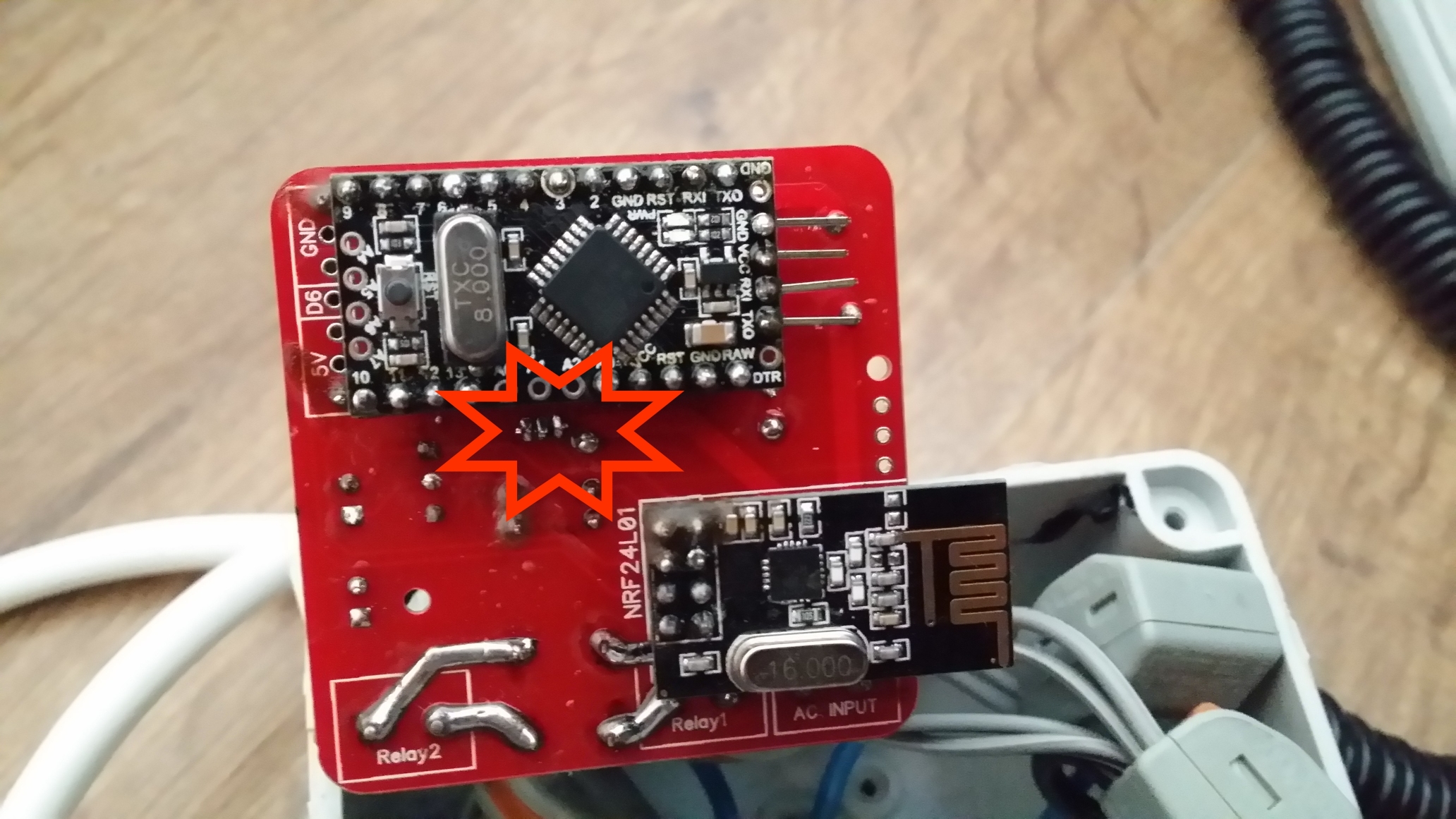
    There's also problem of mixing both main/low voltage everywhere in the board like near the NRF24.

    1 Reply Last reply
    0
    • L Offline
      L Offline
      ludoarchi
      wrote on last edited by
      #108

      Hi
      Noob questions sorry !
      1/ Can i used it with 3way switches ?
      2/ what are the pins 7 GND and 4 for ?
      Thinks

      mr_constM 1 Reply Last reply
      0
      • L ludoarchi

        Hi
        Noob questions sorry !
        1/ Can i used it with 3way switches ?
        2/ what are the pins 7 GND and 4 for ?
        Thinks

        mr_constM Offline
        mr_constM Offline
        mr_const
        wrote on last edited by mr_const
        #109

        @ludoarchi

        @ludoarchi said:

        2/ what are the pins 7 GND and 4 for ?

        7 and 4 pins are mapped to 7 and 4 in/out of an arduino module. GND is for ground. These pins could be used to manually control relay state.

        L 1 Reply Last reply
        0
        • mr_constM mr_const

          @ludoarchi

          @ludoarchi said:

          2/ what are the pins 7 GND and 4 for ?

          7 and 4 pins are mapped to 7 and 4 in/out of an arduino module. GND is for ground. These pins could be used to manually control relay state.

          L Offline
          L Offline
          ludoarchi
          wrote on last edited by
          #110

          @mr_const ok i understand ! Thinks

          1 Reply Last reply
          0
          • rozpruwaczR Offline
            rozpruwaczR Offline
            rozpruwacz
            wrote on last edited by rozpruwacz
            #111

            hi, great project. I have one idea, is it possible to add current and voltage measurement ?

            1 Reply Last reply
            0
            • Sander CrombeenS Offline
              Sander CrombeenS Offline
              Sander Crombeen
              wrote on last edited by
              #112

              Ordered all the components for this project but now i see there are 12 v solid state relays on the list?? mine is not working, does it not need to have 5V version??

              1 Reply Last reply
              0
              • AchimA Offline
                AchimA Offline
                Achim
                wrote on last edited by
                #113

                Hello,
                one question to the SSR Relay. The Arduino works with 5V, the SSR in the BOM is a 12V type. Is this a mistake? According to the Datasheet of the relay, the 12V type has an operating range from 9,6v to 14,4V

                mr_constM 1 Reply Last reply
                0
                • AchimA Achim

                  Hello,
                  one question to the SSR Relay. The Arduino works with 5V, the SSR in the BOM is a 12V type. Is this a mistake? According to the Datasheet of the relay, the 12V type has an operating range from 9,6v to 14,4V

                  mr_constM Offline
                  mr_constM Offline
                  mr_const
                  wrote on last edited by
                  #114

                  @Achim looks like a mistake in BOM (maybe that aliexpress listing has changed). Project uses same relay, but 5V version is needed.

                  JonnyDev13J 1 Reply Last reply
                  1
                  • tonnerre33T Offline
                    tonnerre33T Offline
                    tonnerre33
                    Hardware Contributor
                    wrote on last edited by tonnerre33
                    #115

                    Hello all,

                    I have finished to assemble one of this board today.

                    You can see some pictures of my board here :
                    http://www.photorapide.com/albums/jordan/khreln/ac-dc-double-solid-state-relay-module.html

                    If you want more pictures, ask me ;)

                    The skecth works fine.

                    Thx for this project.

                    okosO 1 Reply Last reply
                    0
                    • tonnerre33T tonnerre33

                      Hello all,

                      I have finished to assemble one of this board today.

                      You can see some pictures of my board here :
                      http://www.photorapide.com/albums/jordan/khreln/ac-dc-double-solid-state-relay-module.html

                      If you want more pictures, ask me ;)

                      The skecth works fine.

                      Thx for this project.

                      okosO Offline
                      okosO Offline
                      okos
                      wrote on last edited by okos
                      #116

                      @tonnerre33
                      Avesome photogallery :smile:
                      whose sketch you used? because I have a problem with phisycal switches if I use sketch of Nca78 (I wrote about this earlier)

                      Nca78N 1 Reply Last reply
                      0
                      • tonnerre33T Offline
                        tonnerre33T Offline
                        tonnerre33
                        Hardware Contributor
                        wrote on last edited by
                        #117

                        I used the sketch of Nca78 (2 months ago) but i only command relays from jeedom.
                        I didn't test physical switch change because i don't have neutral wire in my switch box :(

                        1 Reply Last reply
                        0
                        • okosO okos

                          @tonnerre33
                          Avesome photogallery :smile:
                          whose sketch you used? because I have a problem with phisycal switches if I use sketch of Nca78 (I wrote about this earlier)

                          Nca78N Offline
                          Nca78N Offline
                          Nca78
                          Hardware Contributor
                          wrote on last edited by
                          #118

                          @okos said:

                          @tonnerre33
                          Avesome photogallery :smile:
                          whose sketch you used? because I have a problem with phisycal switches if I use sketch of Nca78 (I wrote about this earlier)

                          Sorry Okos I didn't notice the problem came from my sketch. I'm not using the physical switches at the moment (same reason than tonnerre33, no neutral wire where I have put it at the moment), but I will try to find some time next week to fix the sketch. I'll fix the temperature sending too as sometimes I have some tiny variations of temperature that generate a lot of message sending in a burst and it perturbates other sensors.

                          1 Reply Last reply
                          0
                          • br0wnB Offline
                            br0wnB Offline
                            br0wn
                            wrote on last edited by
                            #119

                            @tonnerre33
                            Just a quick question before i order the PCB, is it realy 4.6x5 cm? (thats what it says on the dirtypcb website, but when i mesure the PCB in the diptrace file, it shows a perfect 5x5 cm.
                            can you please explain?

                            1 Reply Last reply
                            0
                            • Nca78N Offline
                              Nca78N Offline
                              Nca78
                              Hardware Contributor
                              wrote on last edited by
                              #120

                              PCB is 5*5cm.
                              You will also have to include the antenna of the NRF24 that is outside the PCB area.

                              1 Reply Last reply
                              0
                              • tonnerre33T Offline
                                tonnerre33T Offline
                                tonnerre33
                                Hardware Contributor
                                wrote on last edited by
                                #121

                                Yes, it's 5x5cm.
                                For information, i can't place this pcb in my wall box.
                                I'll search other wall box this week in order to find a greater box..

                                If someone want just to test the PCB i can sell one PCB if you are in france ;)
                                I have ordered 10 boards but i don't think use everything.

                                Nca78N br0wnB 2 Replies Last reply
                                0
                                • tonnerre33T tonnerre33

                                  Yes, it's 5x5cm.
                                  For information, i can't place this pcb in my wall box.
                                  I'll search other wall box this week in order to find a greater box..

                                  If someone want just to test the PCB i can sell one PCB if you are in france ;)
                                  I have ordered 10 boards but i don't think use everything.

                                  Nca78N Offline
                                  Nca78N Offline
                                  Nca78
                                  Hardware Contributor
                                  wrote on last edited by
                                  #122

                                  @tonnerre33 said:

                                  If someone want just to test the PCB i can sell one PCB if you are in france ;)
                                  I have ordered 10 boards but i don't think use everything.

                                  Same here if you are in Vietnam or asia, just pay postage and I can send you :p
                                  I have 20 as first order from Seeed took too long to arrive I thought it was lost, so I ordered again from PCBWay. Then received both orders.

                                  @tonnerre33 what is the space available in your wall box ? Would a 43*45mm pcb fit ? Only one relay/switch on my future board but phase + neutral in and phase + neutral out so no need to have additionnal connectors. No SMD, safe distance between tracks + milling. And 0.1'' tracks for load so it should be ok without reinforcing the tracks with solder.

                                  tonnerre33T 1 Reply Last reply
                                  0
                                  • tonnerre33T tonnerre33

                                    Yes, it's 5x5cm.
                                    For information, i can't place this pcb in my wall box.
                                    I'll search other wall box this week in order to find a greater box..

                                    If someone want just to test the PCB i can sell one PCB if you are in france ;)
                                    I have ordered 10 boards but i don't think use everything.

                                    br0wnB Offline
                                    br0wnB Offline
                                    br0wn
                                    wrote on last edited by
                                    #123

                                    @tonnerre33 Thanks buddy,
                                    do you know if dirtypcb are still operational? because i've seen in their website that they want to migrate to another website "dangerousprototype"
                                    did anyone order from them lately?

                                    Nca78N 1 Reply Last reply
                                    0
                                    • br0wnB br0wn

                                      @tonnerre33 Thanks buddy,
                                      do you know if dirtypcb are still operational? because i've seen in their website that they want to migrate to another website "dangerousprototype"
                                      did anyone order from them lately?

                                      Nca78N Offline
                                      Nca78N Offline
                                      Nca78
                                      Hardware Contributor
                                      wrote on last edited by
                                      #124

                                      @br0wn dev.dangerousprototypes.com is supposed to be a test site only, dirtypcb is still functional.

                                      br0wnB 1 Reply Last reply
                                      1
                                      • Nca78N Nca78

                                        @br0wn dev.dangerousprototypes.com is supposed to be a test site only, dirtypcb is still functional.

                                        br0wnB Offline
                                        br0wnB Offline
                                        br0wn
                                        wrote on last edited by
                                        #125

                                        @Nca78

                                        Merci ^^

                                        1 Reply Last reply
                                        0
                                        • Nca78N Nca78

                                          @tonnerre33 said:

                                          If someone want just to test the PCB i can sell one PCB if you are in france ;)
                                          I have ordered 10 boards but i don't think use everything.

                                          Same here if you are in Vietnam or asia, just pay postage and I can send you :p
                                          I have 20 as first order from Seeed took too long to arrive I thought it was lost, so I ordered again from PCBWay. Then received both orders.

                                          @tonnerre33 what is the space available in your wall box ? Would a 43*45mm pcb fit ? Only one relay/switch on my future board but phase + neutral in and phase + neutral out so no need to have additionnal connectors. No SMD, safe distance between tracks + milling. And 0.1'' tracks for load so it should be ok without reinforcing the tracks with solder.

                                          tonnerre33T Offline
                                          tonnerre33T Offline
                                          tonnerre33
                                          Hardware Contributor
                                          wrote on last edited by tonnerre33
                                          #126

                                          @Nca78
                                          I have searched others wall box today but nothing fit (box from france).
                                          A 43x45mm pcb will fit well.
                                          I tried the pcb of the roller-shutter-node (45x46mm) and the wall box fits well.
                                          What do you mean by "no additionnal connectors" ? Will can use physical switches ?

                                          Nca78N 1 Reply Last reply
                                          0
                                          Reply
                                          • Reply as topic
                                          Log in to reply
                                          • Oldest to Newest
                                          • Newest to Oldest
                                          • Most Votes


                                          10

                                          Online

                                          11.7k

                                          Users

                                          11.2k

                                          Topics

                                          113.1k

                                          Posts


                                          Copyright 2025 TBD   |   Forum Guidelines   |   Privacy Policy   |   Terms of Service
                                          • Login

                                          • Don't have an account? Register

                                          • Login or register to search.
                                          • First post
                                            Last post
                                          0
                                          • MySensors
                                          • OpenHardware.io
                                          • Categories
                                          • Recent
                                          • Tags
                                          • Popular