Skip to content
  • MySensors
  • OpenHardware.io
  • Categories
  • Recent
  • Tags
  • Popular
Skins
  • Light
  • Brite
  • Cerulean
  • Cosmo
  • Flatly
  • Journal
  • Litera
  • Lumen
  • Lux
  • Materia
  • Minty
  • Morph
  • Pulse
  • Sandstone
  • Simplex
  • Sketchy
  • Spacelab
  • United
  • Yeti
  • Zephyr
  • Dark
  • Cyborg
  • Darkly
  • Quartz
  • Slate
  • Solar
  • Superhero
  • Vapor

  • Default (No Skin)
  • No Skin
Collapse
Brand Logo
  1. Home
  2. OpenHardware.io
  3. 💬 AC-DC double solid state relay module

💬 AC-DC double solid state relay module

Scheduled Pinned Locked Moved OpenHardware.io
hlk-pm01solid state relaylight switchlightacdc
226 Posts 67 Posters 103.6k Views 65 Watching
  • Oldest to Newest
  • Newest to Oldest
  • Most Votes
Reply
  • Reply as topic
Log in to reply
This topic has been deleted. Only users with topic management privileges can see it.
  • okosO okos

    It possible implement this option in mysensors 2.0 ?

    mfalkviddM Offline
    mfalkviddM Offline
    mfalkvidd
    Mod
    wrote on last edited by
    #102

    @okos it will be included in the next release yes.

    1 Reply Last reply
    0
    • okosO Offline
      okosO Offline
      okos
      wrote on last edited by okos
      #103

      Hello.
      I tried to upload my two boards ( arduino pro mini 8Mhz , 3,3 V ) modified sketches but returned to sketch Nca78 (with DS18B20), unfortunately, does not operate a physical switch. Sometimes phisical switch changes state in domoticz ( not every time ) but relays do not change state.
      Switching on and switching off the lights of domoticz changes state relay without a problem.
      What could be wrong ?

      1 Reply Last reply
      0
      • L Offline
        L Offline
        ludoarchi
        wrote on last edited by
        #104

        Hi

        Does somebody can post a picture of the back side please.

        Thinks

        okosO 1 Reply Last reply
        0
        • L ludoarchi

          Hi

          Does somebody can post a picture of the back side please.

          Thinks

          okosO Offline
          okosO Offline
          okos
          wrote on last edited by
          #105

          @ludoarchi ![alt text]0_1478249022728_20161104_093851.jpg

          L 1 Reply Last reply
          1
          • okosO okos

            @ludoarchi ![alt text]0_1478249022728_20161104_093851.jpg

            L Offline
            L Offline
            ludoarchi
            wrote on last edited by
            #106

            @okos thinks !

            1 Reply Last reply
            1
            • Nca78N Offline
              Nca78N Offline
              Nca78
              Hardware Contributor
              wrote on last edited by
              #107

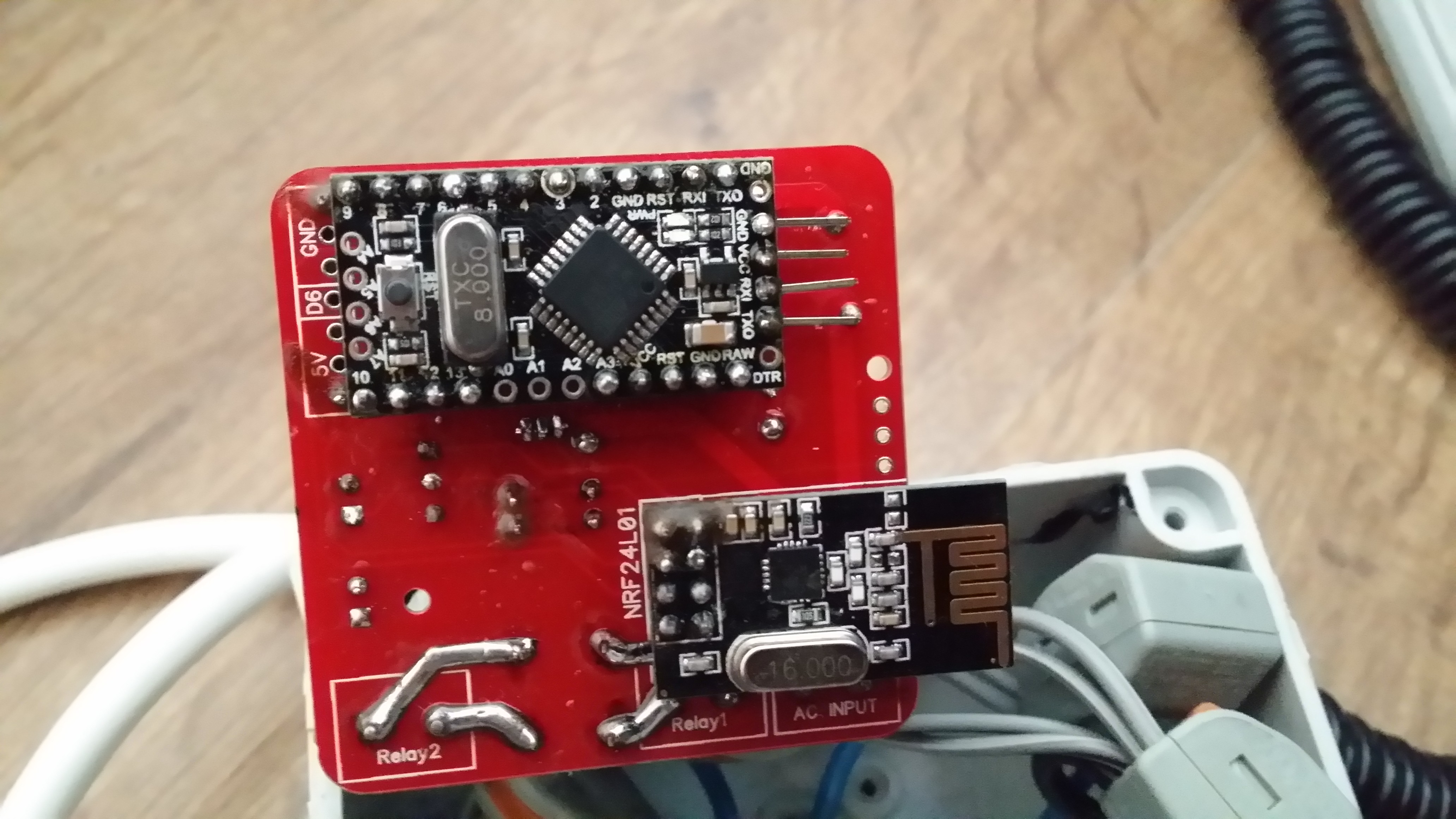
              That's where the biggest problem is on this board. I think the previous revision without the DS18 is safer, here there is less than 2mm creepage/clearance between main and low voltage traces and solder points, not enough :(

              0_1478261384159_1478249033709-20161104_093851.jpg

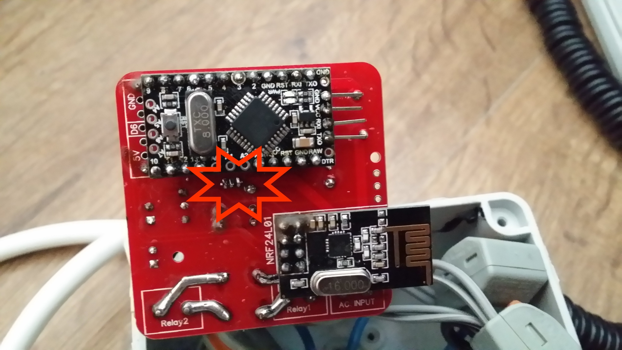
              There's also problem of mixing both main/low voltage everywhere in the board like near the NRF24.

              1 Reply Last reply
              0
              • L Offline
                L Offline
                ludoarchi
                wrote on last edited by
                #108

                Hi
                Noob questions sorry !
                1/ Can i used it with 3way switches ?
                2/ what are the pins 7 GND and 4 for ?
                Thinks

                mr_constM 1 Reply Last reply
                0
                • L ludoarchi

                  Hi
                  Noob questions sorry !
                  1/ Can i used it with 3way switches ?
                  2/ what are the pins 7 GND and 4 for ?
                  Thinks

                  mr_constM Offline
                  mr_constM Offline
                  mr_const
                  wrote on last edited by mr_const
                  #109

                  @ludoarchi

                  @ludoarchi said:

                  2/ what are the pins 7 GND and 4 for ?

                  7 and 4 pins are mapped to 7 and 4 in/out of an arduino module. GND is for ground. These pins could be used to manually control relay state.

                  L 1 Reply Last reply
                  0
                  • mr_constM mr_const

                    @ludoarchi

                    @ludoarchi said:

                    2/ what are the pins 7 GND and 4 for ?

                    7 and 4 pins are mapped to 7 and 4 in/out of an arduino module. GND is for ground. These pins could be used to manually control relay state.

                    L Offline
                    L Offline
                    ludoarchi
                    wrote on last edited by
                    #110

                    @mr_const ok i understand ! Thinks

                    1 Reply Last reply
                    0
                    • rozpruwaczR Offline
                      rozpruwaczR Offline
                      rozpruwacz
                      wrote on last edited by rozpruwacz
                      #111

                      hi, great project. I have one idea, is it possible to add current and voltage measurement ?

                      1 Reply Last reply
                      0
                      • Sander CrombeenS Offline
                        Sander CrombeenS Offline
                        Sander Crombeen
                        wrote on last edited by
                        #112

                        Ordered all the components for this project but now i see there are 12 v solid state relays on the list?? mine is not working, does it not need to have 5V version??

                        1 Reply Last reply
                        0
                        • AchimA Offline
                          AchimA Offline
                          Achim
                          wrote on last edited by
                          #113

                          Hello,
                          one question to the SSR Relay. The Arduino works with 5V, the SSR in the BOM is a 12V type. Is this a mistake? According to the Datasheet of the relay, the 12V type has an operating range from 9,6v to 14,4V

                          mr_constM 1 Reply Last reply
                          0
                          • AchimA Achim

                            Hello,
                            one question to the SSR Relay. The Arduino works with 5V, the SSR in the BOM is a 12V type. Is this a mistake? According to the Datasheet of the relay, the 12V type has an operating range from 9,6v to 14,4V

                            mr_constM Offline
                            mr_constM Offline
                            mr_const
                            wrote on last edited by
                            #114

                            @Achim looks like a mistake in BOM (maybe that aliexpress listing has changed). Project uses same relay, but 5V version is needed.

                            JonnyDev13J 1 Reply Last reply
                            1
                            • tonnerre33T Offline
                              tonnerre33T Offline
                              tonnerre33
                              Hardware Contributor
                              wrote on last edited by tonnerre33
                              #115

                              Hello all,

                              I have finished to assemble one of this board today.

                              You can see some pictures of my board here :
                              http://www.photorapide.com/albums/jordan/khreln/ac-dc-double-solid-state-relay-module.html

                              If you want more pictures, ask me ;)

                              The skecth works fine.

                              Thx for this project.

                              okosO 1 Reply Last reply
                              0
                              • tonnerre33T tonnerre33

                                Hello all,

                                I have finished to assemble one of this board today.

                                You can see some pictures of my board here :
                                http://www.photorapide.com/albums/jordan/khreln/ac-dc-double-solid-state-relay-module.html

                                If you want more pictures, ask me ;)

                                The skecth works fine.

                                Thx for this project.

                                okosO Offline
                                okosO Offline
                                okos
                                wrote on last edited by okos
                                #116

                                @tonnerre33
                                Avesome photogallery :smile:
                                whose sketch you used? because I have a problem with phisycal switches if I use sketch of Nca78 (I wrote about this earlier)

                                Nca78N 1 Reply Last reply
                                0
                                • tonnerre33T Offline
                                  tonnerre33T Offline
                                  tonnerre33
                                  Hardware Contributor
                                  wrote on last edited by
                                  #117

                                  I used the sketch of Nca78 (2 months ago) but i only command relays from jeedom.
                                  I didn't test physical switch change because i don't have neutral wire in my switch box :(

                                  1 Reply Last reply
                                  0
                                  • okosO okos

                                    @tonnerre33
                                    Avesome photogallery :smile:
                                    whose sketch you used? because I have a problem with phisycal switches if I use sketch of Nca78 (I wrote about this earlier)

                                    Nca78N Offline
                                    Nca78N Offline
                                    Nca78
                                    Hardware Contributor
                                    wrote on last edited by
                                    #118

                                    @okos said:

                                    @tonnerre33
                                    Avesome photogallery :smile:
                                    whose sketch you used? because I have a problem with phisycal switches if I use sketch of Nca78 (I wrote about this earlier)

                                    Sorry Okos I didn't notice the problem came from my sketch. I'm not using the physical switches at the moment (same reason than tonnerre33, no neutral wire where I have put it at the moment), but I will try to find some time next week to fix the sketch. I'll fix the temperature sending too as sometimes I have some tiny variations of temperature that generate a lot of message sending in a burst and it perturbates other sensors.

                                    1 Reply Last reply
                                    0
                                    • br0wnB Offline
                                      br0wnB Offline
                                      br0wn
                                      wrote on last edited by
                                      #119

                                      @tonnerre33
                                      Just a quick question before i order the PCB, is it realy 4.6x5 cm? (thats what it says on the dirtypcb website, but when i mesure the PCB in the diptrace file, it shows a perfect 5x5 cm.
                                      can you please explain?

                                      1 Reply Last reply
                                      0
                                      • Nca78N Offline
                                        Nca78N Offline
                                        Nca78
                                        Hardware Contributor
                                        wrote on last edited by
                                        #120

                                        PCB is 5*5cm.
                                        You will also have to include the antenna of the NRF24 that is outside the PCB area.

                                        1 Reply Last reply
                                        0
                                        • tonnerre33T Offline
                                          tonnerre33T Offline
                                          tonnerre33
                                          Hardware Contributor
                                          wrote on last edited by
                                          #121

                                          Yes, it's 5x5cm.
                                          For information, i can't place this pcb in my wall box.
                                          I'll search other wall box this week in order to find a greater box..

                                          If someone want just to test the PCB i can sell one PCB if you are in france ;)
                                          I have ordered 10 boards but i don't think use everything.

                                          Nca78N br0wnB 2 Replies Last reply
                                          0
                                          Reply
                                          • Reply as topic
                                          Log in to reply
                                          • Oldest to Newest
                                          • Newest to Oldest
                                          • Most Votes


                                          15

                                          Online

                                          11.7k

                                          Users

                                          11.2k

                                          Topics

                                          113.0k

                                          Posts


                                          Copyright 2019 TBD   |   Forum Guidelines   |   Privacy Policy   |   Terms of Service
                                          • Login

                                          • Don't have an account? Register

                                          • Login or register to search.
                                          • First post
                                            Last post
                                          0
                                          • MySensors
                                          • OpenHardware.io
                                          • Categories
                                          • Recent
                                          • Tags
                                          • Popular