Problems with first sensors
-
Hello,
A few days ago I build a serial gateway using an arduino nano clone and a NRF24L01 with antenna. My raspberry pi 3 is running domoticz as controller.
Domoticz seems to recognize the serial mysensors gateway (USB) and shows version 2.0.
For testing I build a motion sensor (HC-SR501, arduino nano, NRF24L01) and uploaded a an unmodified mysensors example-sketch. Under setup->hardware->gateway->setup (german translation) I was able to see a child no. 255 (doesn´t the example used child ID 1?), which was named S_ARDUINO_REPEATER_NODE version 1 instead of motion sensor. I was never able to see this in devices.
Tried to upload the sketch once again with a clean installation of the arduino IDE from arduino.cc. Installed the newest IDE version and mysensors 2.0.
But, now on compiling a sketch, the IDE tells me:
In file included from /Users/XX 1/Dropbox/Arduino/MySensors/MotionSensor/MotionSensor.ino:2:0:
/Users/XX/Documents/Arduino/libraries/MySensors/MySensors.h:287:4: error: #error No forward link or gateway feature activated. This means nowhere to send messages! Pretty pointless.
#error No forward link or gateway feature activated. This means nowhere to send messages! Pretty pointless.
^
/Users/XX 1/Dropbox/Arduino/MySensors/MotionSensor/MotionSensor.ino:41:22: fatal error: MySensor.h: No such file or directory
#include <MySensor.h>
^
compilation terminated.
exit status 1The sketch:
#include <MyConfig.h>
#include <MySensors.h>

/**
 * The MySensors Arduino library handles the wireless radio link and protocol
 * between your home built sensors/actuators and HA controller of choice.
 * The sensors forms a self healing radio network with optional repeaters. Each
 * repeater and gateway builds a routing tables in EEPROM which keeps track of the
 * network topology allowing messages to be routed to nodes.
 *
 * Created by Henrik Ekblad <henrik.ekblad@mysensors.org>
 * Copyright (C) 2013-2015 Sensnology AB
 * Full contributor list: https://github.com/mysensors/Arduino/graphs/contributors
 *
 * Documentation: http://www.mysensors.org
 * Support Forum: http://forum.mysensors.org
 *
 * This program is free software; you can redistribute it and/or
 * modify it under the terms of the GNU General Public License
 * version 2 as published by the Free Software Foundation.
 *
 *******************************
 *
 * REVISION HISTORY
 * Version 1.0 - Henrik Ekblad
 *
 * DESCRIPTION
 * Motion Sensor example using HC-SR501
 * http://www.mysensors.org/build/motion
 *
 */

// Enable debug prints
// #define MY_DEBUG

// Enable and select radio type attached
#define MY_RADIO_NRF24
//#define MY_RADIO_RFM69

#include <SPI.h>
#include <MySensor.h>

unsigned long SLEEP_TIME = 120000; // Sleep time between reports (in milliseconds)
#define DIGITAL_INPUT_SENSOR 3   // The digital input you attached your motion sensor.  (Only 2 and 3 generates interrupt!)
#define INTERRUPT DIGITAL_INPUT_SENSOR-2 // Usually the interrupt = pin -2 (on uno/nano anyway)
#define CHILD_ID 1   // Id of the sensor child

// Initialize motion message
MyMessage msg(CHILD_ID, V_TRIPPED);

void setup()
{
  pinMode(DIGITAL_INPUT_SENSOR, INPUT);      // sets the motion sensor digital pin as input
}

void presentation()  {
  // Send the sketch version information to the gateway and Controller
  sendSketchInfo("Motion Sensor", "1.0");

  // Register all sensors to gw (they will be created as child devices)
  present(CHILD_ID, S_MOTION);
}

void loop()
{
  // Read digital motion value
  boolean tripped = digitalRead(DIGITAL_INPUT_SENSOR) == HIGH;

  Serial.println(tripped);
  send(msg.set(tripped?"1":"0"));  // Send tripped value to gw

  // Sleep until interrupt comes in on motion sensor. Send update every two minute.
  sleep(INTERRUPT,CHANGE, SLEEP_TIME);
}
I am very frustrated. Why don´t I see the sensor in domiticz and why does the IDE not compile the sketch. This error occurs on my mac and my windows pc.
Little help would be great... thanks.
-
Hello.
I don't think this is an unmodified sketch ;) There are multiple wrong things like the two different Mysensors includes etc.. Here is the right one : https://github.com/mysensors/MySensors/blob/development/examples/MotionSensor/MotionSensor.ino
And you need to config your sketch. You can read this, it can help you:
https://www.mysensors.org/about/arduino#installing-the-sensor-libraries
https://forum.mysensors.org/topic/4276/converting-a-sketch-from-1-5-x-to-2-0-x -
Oh, I thought the examples are ready for mysensors library 2.0. So, first step I have to do is to change some lines in the sketch...
But, I already used the "manage library" function in the IDE and installed mysensors 2.0. So, I am wondering why all these errors still come up.
-
Your new code from github for the motion compiled without any problems.
2 days ago I uploaded the serial gateway sketch from https://www.mysensors.org/build/serial_gateway. This sketch is not compatible to mysensor library 2.0 ?
I found some new example code on github, but at the moment, I don´t really know how to change the sketch to 2.0 compatibility.
-
yes sketch are ready, the sketch from example folder is ok.
perhaps you didn't paid attention, but imho you have changed something...Look at the top of your sketch, mysensors is two times included and not right. And if you look at the sketch I've linked (which is from example folder), you will see it's done once like this#include <Mysensors.h>And you have this in your :
#include <MyConfig.h> #include <MySensors.h> ... #include <MySensor.h> -
ah ok. I don't know for these sketch. But those from the arduino example folder should be ok.
If not, clean your arduino install, and install it again. with the help from the links above, this should be ok.
I hope it helps. -
Nano seems to be damaged. Trying a new one tomorrow.
One more question, please: I downloadee mysensors library 20.
As I am using a serial hateway, I notices the gateway sketch uses the old gw.xxx structure. Do I have to modfiy the sketch on my own for preparing it for library 2.0? (My programming skills are under development). On githib the sketch is very basic, there is missing a lot?! -
where do you see that gateway use old structure?
the serial gw sketch you have in arduino ide should be the same as github. if not, you have not well updated your lib..
don't worry, the sketch is very basic but it works. it's because lot of stuff is hidden for easing the lib use. -
To me as a newbie it is a bit confusing...
This sketch comes from mysensors.org:
**
 * The MySensors Arduino library handles the wireless radio link and protocol
 * between your home built sensors/actuators and HA controller of choice.
 * The sensors forms a self healing radio network with optional repeaters. Each
 * repeater and gateway builds a routing tables in EEPROM which keeps track of the
 * network topology allowing messages to be routed to nodes.
 *
 * Created by Henrik Ekblad <henrik.ekblad@mysensors.org>
 * Copyright (C) 2013-2015 Sensnology AB
 * Full contributor list: https://github.com/mysensors/Arduino/graphs/contributors
 *
 * Documentation: http://www.mysensors.org
 * Support Forum: http://forum.mysensors.org
 *
 * This program is free software; you can redistribute it and/or
 * modify it under the terms of the GNU General Public License
 * version 2 as published by the Free Software Foundation.
 *
 *******************************
 *
 * DESCRIPTION
 * The ArduinoGateway prints data received from sensors on the serial link.
 * The gateway accepts input on seral which will be sent out on radio network.
 *
 * The GW code is designed for Arduino Nano 328p / 16MHz
 *
 * Wire connections (OPTIONAL):
 * - Inclusion button should be connected between digital pin 3 and GND
 * - RX/TX/ERR leds need to be connected between +5V (anode) and digital pin 6/5/4 with resistor 270-330R in a series
 *
 * LEDs (OPTIONAL):
 * - To use the feature, uncomment WITH_LEDS_BLINKING in MyConfig.h
 * - RX (green) - blink fast on radio message recieved. In inclusion mode will blink fast only on presentation recieved
 * - TX (yellow) - blink fast on radio message transmitted. In inclusion mode will blink slowly
 * - ERR (red) - fast blink on error during transmission error or recieve crc error
 *
 */

#define NO_PORTB_PINCHANGES

#include <MySigningNone.h>
#include <MyTransportRFM69.h>
#include <MyTransportNRF24.h>
//#include <MyHwATMega328.h>
#include <MySigningAtsha204Soft.h>
#include <MySigningAtsha204.h>

#include <SPI.h>
#include <MyParserSerial.h>
#include <MySensor.h>
#include <stdarg.h>
#include <PinChangeInt.h>
#include "GatewayUtil.h"

#define INCLUSION_MODE_TIME 1 // Number of minutes inclusion mode is enabled
#define INCLUSION_MODE_PIN  3 // Digital pin used for inclusion mode button
#define RADIO_ERROR_LED_PIN 4  // Error led pin
#define RADIO_RX_LED_PIN    6  // Receive led pin
#define RADIO_TX_LED_PIN    5  // the PCB, on board LED

// NRFRF24L01 radio driver (set low transmit power by default)
MyTransportNRF24 transport(RF24_CE_PIN, RF24_CS_PIN, RF24_PA_LEVEL_GW);
//MyTransportRFM69 transport;

// Message signing driver (signer needed if MY_SIGNING_FEATURE is turned on in MyConfig.h)
//MySigningNone signer;
//MySigningAtsha204Soft signer;
//MySigningAtsha204 signer;

// Hardware profile
MyHwATMega328 hw;

// Construct MySensors library (signer needed if MY_SIGNING_FEATURE is turned on in MyConfig.h)
// To use LEDs blinking, uncomment WITH_LEDS_BLINKING in MyConfig.h
#ifdef WITH_LEDS_BLINKING
MySensor gw(transport, hw /*, signer*/, RADIO_RX_LED_PIN, RADIO_TX_LED_PIN, RADIO_ERROR_LED_PIN);
#else
MySensor gw(transport, hw /*, signer*/);
#endif

char inputString[MAX_RECEIVE_LENGTH] = "";    // A string to hold incoming commands from serial/ethernet interface
int inputPos = 0;
boolean commandComplete = false;  // whether the string is complete

void parseAndSend(char *commandBuffer);

void output(const char *fmt, ... ) {
   va_list args;
   va_start (args, fmt );
   vsnprintf_P(serialBuffer, MAX_SEND_LENGTH, fmt, args);
   va_end (args);
   Serial.print(serialBuffer);
}


void setup()
{
  gw.begin(incomingMessage, 0, true, 0);

  setupGateway(INCLUSION_MODE_PIN, INCLUSION_MODE_TIME, output);

  // Add interrupt for inclusion button to pin
  PCintPort::attachInterrupt(pinInclusion, startInclusionInterrupt, RISING);


  // Send startup log message on serial
  serial(PSTR("0;0;%d;0;%d;Gateway startup complete.\n"),  C_INTERNAL, I_GATEWAY_READY);
}

void loop()
{
  gw.process();

  checkButtonTriggeredInclusion();
  checkInclusionFinished();

  if (commandComplete) {
    // A command wass issued from serial interface
    // We will now try to send it to the actuator
    parseAndSend(gw, inputString);
    commandComplete = false;
    inputPos = 0;
  }
}


/*
  SerialEvent occurs whenever a new data comes in the
 hardware serial RX.  This routine is run between each
 time loop() runs, so using delay inside loop can delay
 response.  Multiple bytes of data may be available.
 */
void serialEvent() {
  while (Serial.available()) {
    // get the new byte:
    char inChar = (char)Serial.read();
    // if the incoming character is a newline, set a flag
    // so the main loop can do something about it:
    if (inputPos<MAX_RECEIVE_LENGTH-1 && !commandComplete) {
      if (inChar == '\n') {
        inputString[inputPos] = 0;
        commandComplete = true;
      } else {
        // add it to the inputString:
        inputString[inputPos] = inChar;
        inputPos++;
      }
    } else {
       // Incoming message too long. Throw away
        inputPos = 0;
    }
  }
}
Looks like the sketch for mysensors library 1.x.
And this one is from github:
 /**
 * The MySensors Arduino library handles the wireless radio link and protocol
 * between your home built sensors/actuators and HA controller of choice.
 * The sensors forms a self healing radio network with optional repeaters. Each
 * repeater and gateway builds a routing tables in EEPROM which keeps track of the
 * network topology allowing messages to be routed to nodes.
 *
 * Created by Henrik Ekblad <henrik.ekblad@mysensors.org>
 * Copyright (C) 2013-2015 Sensnology AB
 * Full contributor list: https://github.com/mysensors/Arduino/graphs/contributors
 *
 * Documentation: http://www.mysensors.org
 * Support Forum: http://forum.mysensors.org
 *
 * This program is free software; you can redistribute it and/or
 * modify it under the terms of the GNU General Public License
 * version 2 as published by the Free Software Foundation.
 *
 *******************************
 *
 * DESCRIPTION
 * The ArduinoGateway prints data received from sensors on the serial link.
 * The gateway accepts input on seral which will be sent out on radio network.
 *
 * The GW code is designed for Arduino Nano 328p / 16MHz
 *
 * Wire connections (OPTIONAL):
 * - Inclusion button should be connected between digital pin 3 and GND
 * - RX/TX/ERR leds need to be connected between +5V (anode) and digital pin 6/5/4 with resistor 270-330R in a series
 *
 * LEDs (OPTIONAL):
 * - To use the feature, uncomment MY_LEDS_BLINKING_FEATURE in MyConfig.h
 * - RX (green) - blink fast on radio message recieved. In inclusion mode will blink fast only on presentation recieved
 * - TX (yellow) - blink fast on radio message transmitted. In inclusion mode will blink slowly
 * - ERR (red) - fast blink on error during transmission error or recieve crc error
 *
 */

// Enable debug prints to serial monitor
#define MY_DEBUG


// Enable and select radio type attached
#define MY_RADIO_NRF24
//#define MY_RADIO_RFM69

// Set LOW transmit power level as default, if you have an amplified NRF-module and
// power your radio separately with a good regulator you can turn up PA level.
#define MY_RF24_PA_LEVEL RF24_PA_LOW

// Enable serial gateway
#define MY_GATEWAY_SERIAL

// Define a lower baud rate for Arduino's running on 8 MHz (Arduino Pro Mini 3.3V & SenseBender)
#if F_CPU == 8000000L
#define MY_BAUD_RATE 38400
#endif

// Flash leds on rx/tx/err
#define MY_LEDS_BLINKING_FEATURE
// Set blinking period
#define MY_DEFAULT_LED_BLINK_PERIOD 300

// Inverses the behavior of leds
//#define MY_WITH_LEDS_BLINKING_INVERSE

// Enable inclusion mode
#define MY_INCLUSION_MODE_FEATURE
// Enable Inclusion mode button on gateway
#define MY_INCLUSION_BUTTON_FEATURE

// Inverses behavior of inclusion button (if using external pullup)
//#define MY_INCLUSION_BUTTON_EXTERNAL_PULLUP

// Set inclusion mode duration (in seconds)
#define MY_INCLUSION_MODE_DURATION 60
// Digital pin used for inclusion mode button
#define MY_INCLUSION_MODE_BUTTON_PIN  3

// Uncomment to override default HW configurations
//#define MY_DEFAULT_ERR_LED_PIN 4  // Error led pin
//#define MY_DEFAULT_RX_LED_PIN  6  // Receive led pin
//#define MY_DEFAULT_TX_LED_PIN  5  // the PCB, on board LED

#include <SPI.h>
#include <MySensors.h>

void setup() {
  // Setup locally attached sensors
}

void presentation() {
 // Present locally attached sensors
}

void loop() {
  // Send locally attached sensor data here
}
To me ot looks like this is meant for mysensors.org 2.0, which looks incomplete. Think, they have to be merged ?
-
I know the difference between the two versions. But, as I said, no need to merge.
Please note:-
The examples you found on mysensors.org are, i guess, not all updated yet. but mysensors team is working hard, it's lot of work ;)
-
The example from github are compiled for mysensors 2. You think this is incomplete but that's wrong. The stuff you think missing is simply hidden. For easing noob experience.
-
So only 1.x older user sketch need to be updated to 2.0. If you are starting with mysensors, i don't think you have older sketch to convert, isn't it?
-
if not already done., use https://www.mysensors.org/about/arduino#installing-the-sensor-libraries to install the latest lib from Arduino software
-
Then no need to go to mysensors or git to get the latest examples. It's available in Arduino software. File Menu\Examples\Mysensors
For discovering Arduino software, or arduino in general, you can have a look at
https://www.arduino.cc/en/Guide/HomePage
https://www.arduino.cc/en/Tutorial/HomePage
https://www.arduino.cc/en/Reference/HomePage -
-
It is very frustrating...
Uploaded the serial gateway sketch from examples ro my serial gateway (not serialgateway485). I just modified the baud rate to 115200. domoticz recognizes the gateway as version 2.0.
I also uploaded the motion sketch from examples to a new arduino nano and modified nothing.
Domoticz now is able to see the node, but it is named unknown. The child ID 255 (that must be wrong) is named S_ARDUINO_REPEATER_NODE - that is wrong. It has to be S_MOTION. Despite I was using the newest sketch, domoticz calls it version 1.0.
Could someone tell me the solution, please?
-
The version 1.0 comes from this piece of code and has nothing to do with the mysensors version.
void presentation()  {
  // Send the sketch version information to the gateway and Controller
  sendSketchInfo("Motion Sensor", "1.0");
It would be nice to see the serial output from your node when you connect it to your gateway.
Also try to comment out the sleep function so there is less code that could cause a problem. -
This is the code for my serial gateway to domoticz (arduino nano, NRF24L01+PA+ANTENNA) I am actually using...
 * The MySensors Arduino library handles the wireless radio link and protocol
 * between your home built sensors/actuators and HA controller of choice.
 * The sensors forms a self healing radio network with optional repeaters. Each
 * repeater and gateway builds a routing tables in EEPROM which keeps track of the
 * network topology allowing messages to be routed to nodes.
 *
 * Created by Henrik Ekblad <henrik.ekblad@mysensors.org>
 * Copyright (C) 2013-2015 Sensnology AB
 * Full contributor list: https://github.com/mysensors/Arduino/graphs/contributors
 *
 * Documentation: http://www.mysensors.org
 * Support Forum: http://forum.mysensors.org
 *
 * This program is free software; you can redistribute it and/or
 * modify it under the terms of the GNU General Public License
 * version 2 as published by the Free Software Foundation.
 *
 *******************************
 *
 * DESCRIPTION
 * The ArduinoGateway prints data received from sensors on the serial link.
 * The gateway accepts input on seral which will be sent out on radio network.
 *
 * The GW code is designed for Arduino Nano 328p / 16MHz
 *
 * Wire connections (OPTIONAL):
 * - Inclusion button should be connected between digital pin 3 and GND
 * - RX/TX/ERR leds need to be connected between +5V (anode) and digital pin 6/5/4 with resistor 270-330R in a series
 *
 * LEDs (OPTIONAL):
 * - To use the feature, uncomment MY_LEDS_BLINKING_FEATURE in MyConfig.h
 * - RX (green) - blink fast on radio message recieved. In inclusion mode will blink fast only on presentation recieved
 * - TX (yellow) - blink fast on radio message transmitted. In inclusion mode will blink slowly
 * - ERR (red) - fast blink on error during transmission error or recieve crc error
 *
 */

// Enable debug prints to serial monitor
#define MY_DEBUG


// Enable and select radio type attached
#define MY_RADIO_NRF24
//#define MY_RADIO_RFM69

// Set LOW transmit power level as default, if you have an amplified NRF-module and
// power your radio separately with a good regulator you can turn up PA level.
#define MY_RF24_PA_LEVEL RF24_PA_LOW

// Enable serial gateway
#define MY_GATEWAY_SERIAL

// Define a lower baud rate for Arduino's running on 8 MHz (Arduino Pro Mini 3.3V & SenseBender)
#if F_CPU == 8000000L
#define MY_BAUD_RATE 115200
#endif

// Flash leds on rx/tx/err
#define MY_LEDS_BLINKING_FEATURE
// Set blinking period
#define MY_DEFAULT_LED_BLINK_PERIOD 300

// Inverses the behavior of leds
//#define MY_WITH_LEDS_BLINKING_INVERSE

// Enable inclusion mode
#define MY_INCLUSION_MODE_FEATURE
// Enable Inclusion mode button on gateway
#define MY_INCLUSION_BUTTON_FEATURE

// Inverses behavior of inclusion button (if using external pullup)
//#define MY_INCLUSION_BUTTON_EXTERNAL_PULLUP

// Set inclusion mode duration (in seconds)
#define MY_INCLUSION_MODE_DURATION 60
// Digital pin used for inclusion mode button
#define MY_INCLUSION_MODE_BUTTON_PIN  3

// Uncomment to override default HW configurations
//#define MY_DEFAULT_ERR_LED_PIN 4  // Error led pin
//#define MY_DEFAULT_RX_LED_PIN  6  // Receive led pin
//#define MY_DEFAULT_TX_LED_PIN  5  // the PCB, on board LED

#include <SPI.h>
#include <MySensors.h>

void setup() {
  // Setup locally attached sensors
}

void presentation() {
 // Present locally attached sensors
}

void loop() {
  // Send locally attached sensor data here
}
And this sketch is for the motion sensor (arduino nano, HC-SR501 and NRF24L01+PA+ANTENNA)...
 * The MySensors Arduino library handles the wireless radio link and protocol
 * between your home built sensors/actuators and HA controller of choice.
 * The sensors forms a self healing radio network with optional repeaters. Each
 * repeater and gateway builds a routing tables in EEPROM which keeps track of the
 * network topology allowing messages to be routed to nodes.
 *
 * Created by Henrik Ekblad <henrik.ekblad@mysensors.org>
 * Copyright (C) 2013-2015 Sensnology AB
 * Full contributor list: https://github.com/mysensors/Arduino/graphs/contributors
 *
 * Documentation: http://www.mysensors.org
 * Support Forum: http://forum.mysensors.org
 *
 * This program is free software; you can redistribute it and/or
 * modify it under the terms of the GNU General Public License
 * version 2 as published by the Free Software Foundation.
 *
 *******************************
 *
 * REVISION HISTORY
 * Version 1.0 - Henrik Ekblad
 *
 * DESCRIPTION
 * Motion Sensor example using HC-SR501
 * http://www.mysensors.org/build/motion
 *
 */

// Enable debug prints
// #define MY_DEBUG

// Enable and select radio type attached
#define MY_RADIO_NRF24
//#define MY_RADIO_RFM69

#include <SPI.h>
#include <MySensors.h>

unsigned long SLEEP_TIME = 120000; // Sleep time between reports (in milliseconds)
#define DIGITAL_INPUT_SENSOR 3   // The digital input you attached your motion sensor.  (Only 2 and 3 generates interrupt!)
#define CHILD_ID 1   // Id of the sensor child

// Initialize motion message
MyMessage msg(CHILD_ID, V_TRIPPED);

void setup()
{
  pinMode(DIGITAL_INPUT_SENSOR, INPUT);      // sets the motion sensor digital pin as input
}

void presentation()  {
  // Send the sketch version information to the gateway and Controller
  sendSketchInfo("Motion Sensor", "1.0");

  // Register all sensors to gw (they will be created as child devices)
  present(CHILD_ID, S_MOTION);
}

void loop()
{
  // Read digital motion value
  boolean tripped = digitalRead(DIGITAL_INPUT_SENSOR) == HIGH;

  Serial.println(tripped);
  send(msg.set(tripped?"1":"0"));  // Send tripped value to gw

  // Sleep until interrupt comes in on motion sensor. Send update every two minute.
  sleep(digitalPinToInterrupt(DIGITAL_INPUT_SENSOR), CHANGE, SLEEP_TIME);
}
Domoticz still recognizes the motion sensor as "unknown" and S_ARDUINO_REPEATER.
And, the debug seriell monitor tells me:
Starting sensor (RNNNA-, 2.0.0)
TSM:INIT
TSM:RADIO:OK
TSM:FPAR
TSP:MSG:SEND 255-255-255-255 s=255,c=3,t=7,pt=0,l=0,sg=0,ft=0,st=bc:
TSM:FPAR
TSP:MSG:SEND 255-255-255-255 s=255,c=3,t=7,pt=0,l=0,sg=0,ft=0,st=bc:
TSM:FPAR
TSP:MSG:SEND 255-255-255-255 s=255,c=3,t=7,pt=0,l=0,sg=0,ft=0,st=bc:
TSM:FPAR
TSP:MSG:SEND 255-255-255-255 s=255,c=3,t=7,pt=0,l=0,sg=0,ft=0,st=bc:
!TSM:FPAR:FAIL
!TSM:FAILURE
TSM:PDT
Hope, someone can help - it is very frustrating.
-
Okay, could you please tell me how to do that.
At the moment I do not know where to find it.@blebbens connect the gateway to your computer usb port and look at the serial to see the debug log.
In addition where does domoticz show the "unknown" sensor? In the hardware log there is always one with id 255 for the node.
From you log I read a lot of "failed" messages. This indicates transmission errors which could result from your amplified radio's. These a more error prone than the non amplified ones. For testing you better use the non amplified.
-
I don't know about domoticz but perhaps you can get the logs. Or use MYSController.
Otherwise, when you need it, you can debug gw and node on your computer. Just connect both devices to your computer. Then of course this is not connected to domoticz but for debugging i often do this, it's useful.
So:
- connect gw+node to your computer
- then use Serial monitor from arduino if you want, to monitor one device. choose right baudrate and comport of course
- and for other device, use another serial monitor like putty etc..
or a sniffer if you really want to keep it connected to your controller. But for noobs, i would advice to simply use two serial monitor when you need to debug, easier..
-
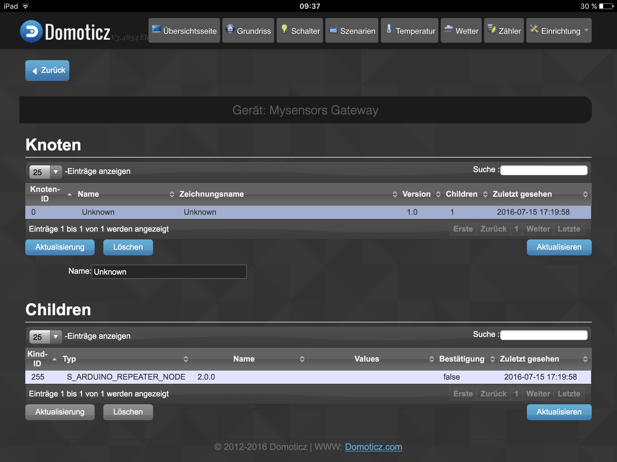
This is what domoticz looks like...
Connecting the serial gateway to my computer means, I can not connect it to domoticz ?
For debugging I have to enable #define MY_DEBUG ?
Or, is there a way to read the log file on the gateway ?@blebbens your domoticz screen looks fine. No errors but also no sensors reported. Only the node is known.
As @scalz mentioned, just connect the node and gateway to your computer watch what happens on the serial monitor (arduino idea or whatever you are using) the node does not have to be connected to domoticz for initial debugging.