💬 Battery Powered Sensors


  • @evb little info regarding the LED on the SCK pin.
    Assuming it is a red LED with a forward voltage of 1.8V, considering the chip is powered with 3.3V and considering the 330 Ohm resistor in series with the LED, the additional current draw when SCK goes high should be about 4.5mA.


  • @canique you confirm my suspicions. For the moment I have 3 working battery nodes with the pro mini and the RFM69HW. We will see how long the batteries are going to last. Normally it should be one year.

    I'm constrained by the maximum dimensions of the sensor node. The case must go inside the PVC door frame, so it can be maximum 20mm width on 17mm height, the length is not a constraint. 🙂
    20201114_133327.jpg
    I had to solder the RFM69HW in line with the pro mini.
    The MK2 boards are unfortunately too wide.


  • Mod

    @evb how's the range of your node? Being enclosed in aluminum will definitely reduce range.


  • @evb I can't see it clearly on the picture but this seems like a reed sensor to me.
    Well, usually the transmitter does not have to be at some specific location. There are reed sensors based on magnets (connected with 2 wires to the transmitter). As soon as the magnets are close to each other, a small current flows (or vice versa). They are just attached to the window/door with some sticky adhesive. The transmitter can well be a meter away.

    I can say from experience with Atmega328P, that when drawing ~24uA in sleep and sending every 30 seconds a single battery lasts ~ 1 year.
    This can all be calculated (rough estimates).
    A basic online calculator for this kind of stuff can be found @ https://oregonembedded.com/batterycalc.htm


  • @Yveaux It is not a aluminium door frame, but a PVC door frame (plastic).
    The problem is that my gateway is in the extension of the brick wall, about 15m away in the garage at the backyard. So I have a 5m brick wall between de node and the gateway 😞
    This means that the reliability of the connection is not good, so I had to place a repeater node between them.


  • @canique no, the purpose of the node is to know when the door is locked by the bolt, not only closed. What you see are simply 2 battery springs and the bolt of the lock closes the contact.
    I can move the node more upwards the door frame (and I will do it if the radio connection is still not reliable with the repeater).
    In order to preserve domestic peace, I placed the nodes in the door frame, invisible when the door is closed: no visible dangling wires and no visible boxes.

    Maybe an idea for a MK3 version of your board as wide as the RFM69HW 😉


  • Hello

    I created battery powered node running on 2x 1.5V AA batteries with DC-DC step up booster. But the step up booster makes audible noise (very tiny beeping) when the radio is transmitting.

    It is this step up booster https://www.laskarduino.cz/step-up-boost-menic-s-me2108-33v-480ma/

    Is there any way to solve it?

    Thanks

    Tomas


  • Contest Winner

    @tssk First things that comes to my mind is that you might draw too much power (but no expert) did you measure it?


  • @tssk There is a name for this noise: it is called "coil whine". In German "Spulenfiepen". It stems from the inductor - I wouldn't know any way to get rid of it.
    My mainboard or power supply on my PC creates similar noise when the CPU goes in certain doze modes.


  • @tssk I heard that people got rid of or at least reduced the coil whine by coating the windings of an audible inductor with non-conductive materials like epoxy resin or even hot glue to reduce the vibrations.

    Of course, I woudn't mess with expensive PC hardware, but I guess there's not much to loose with a cheap boost module like this.


  • Thanks all for the response.

    @BearWithBeard I will start googling about such solution.

    Do you think using different step up booster might help? Could someone recommend something?


  • I am biased since I run that website but I can recommend https://www.canique.com/boost
    I've never heard it making noise.


  • @canique Thanks for the recommendation if I do not find fix for the model I am using I will consider buying it.

    I will try to hot glue the side with the coil as I found on some pages. Any ideas / warnings? 🙂


  • @tssk Most of these boosters have a grounded backplane, perhaps trying to re-orientate the inductor so the backplane acts a shield to direct RF may be an option to try ?
    If the noise in on the power line I've heard of some managing to block it with a VR circuit if the voltage drop is acceptable, but never tried it.


  • @zboblamont It is not electrical noise but audio noise I can hear. Sorry if I use improper terms.


  • @tssk My misconception.


  • @tssk If the item is not going to be too hot then hot melted candle wax dripped over the coils will probably help.


  • So I used hot glue and it is better. Now I can hear the squeal only when I put my ear directly to the PCB. Thanks for the tips.

    @TheoL I have no idea how to measure that.

    I noticed that when the radio is transmitting the LED on the Arduino Pro Mini (not the power one) starts blinking very tiny. I still plan to remove the power LED and voltage regulator from the Arduino.


  • Mod

    @tssk the led blinks because it is connected to the same pin as the SCK pin used by the nrf24.


  • @mfalkvidd You are right 🙂 I did not know that.

    SPI: 10 (SS), 11 (MOSI), 12 (MISO), 13 (SCK). These pins support SPI communication, which, although provided by the underlying hardware, is not currently included in the Arduino language.
    LED: 13. There is a built-in LED connected to digital pin 13. When the pin is HIGH value, the LED is on, when the pin is LOW, it's off.

    https://www.arduino.cc/en/pmwiki.php?n=Main/ArduinoBoardProMini

    Should I remove the LED to save power? Or it is marginal?


  • Mod

    @tssk it is marginal


  • @mfalkvidd Thanks.


  • Hello

    I would like to ask for help with passive battery powered node I created with following components:

    • Arduino pro mini 8MHz - voltage regulator and power LED removed
    • SX1276 based 868MHz LoRa radio
    • BME680 sensor
    • DC-DC 3.3V step-up booster

    I created a battery measuring circuit according to scheme on this page ( https://www.mysensors.org/build/battery ).

    The problem is the two fresh new AA batteries lasted less than 14 days and stopped when the circuit measured 36%.

    2x1.5V AA Aerocell following start and end values:

    09.02.2021 16:45 102% (start) : 1.610V and 1.610V
    22.02.2021 04:15 36% (end) : 1.001V and -0.150V

    2021-02-25_07-36.png

    The node code is sleeping for 6 minutes between each sensing and sending data.

    sleep(180000);
    

    14 days seems very short to me. Is that normal? Is there something I can to make it last longer?

    Thanks


  • Mod

    @tssk could you post your sketch? Some things that could draw power:

    • bme not turned off properly when sleeping the node
    • lora transmits can take a long time, depending on which settings are used

    Which booster are you using? A good booster will use almost no power when the node is sleeping. A bad booster will consume almost as much as if the node was not sleeping, so the performance of the booster will make a huge difference.


  • @tssk Sending 240 messages a day is quite a lot for a battery node. I think you will need higher capacity batteries with that frequency of sending (is it really essential to send that often I wonder?).

    Anyway, I am also testing battery nodes and as far as I can see the lora and bme are likely taking a lot of power. They must be 'put to sleep' as much as possible. AFAIK lora is an abbreviation of 'long range' and therefore means 'more power'. Can you test the current drawn by just the radio in sleep and transmitting?

    Also, bootloader - I highly recommend using the minicore bootloader with internal 8MHz, bod as you wish (I ususally disable) and try again. My sleeping nodes use less than 5uA in sleep and I am trying to get that even lower this week.

    Also check the value of pull-upresistors on the boards, they can be on the low side and perhaps better with higher value external ones (something I hope to test tomorrow as it happens).

    Also temperature and humidity will have an effect. I put one test node on a colder NE facing window which has slept all the time except a twice daily battery check and send value only if changed. It is the only node to have changed from 100% to 99% in a week, so the colder window is clearly having an effect on the battery life in this situation.

    As @mfalkvidd implied I would get rid of the stepup booster if at all possible, they are not so efficient and can produce a lot of noise on the power line. Can you go to 3xAA batteries? What about an 18650 li-on or two in parallel?

    Finally check solder joints. A dry joint or cold joint may look OK but measure them with a meter just to make sure.


  • @mfalkvidd

    • I did not know that I need to turn BME off ů how to do that?

    • Only thing I found is that Arduino has deepSleep() - but I am not sure if I can use it.

    • I am using the default Bw125Cr45Sf128 but thinking about testing Bw125Cr48Sf4096 to achieve greater range.

    • Booster is the whining one - https://www.laskarduino.cz/step-up-boost-menic-s-me2108-33v-480ma/

    • Is there a way I can measure power draw with multimeter?

    // Enable debug prints
    //#define MY_DEBUG
    
    // Enable passive mode
    #define MY_PASSIVE_NODE
    
    // Passive mode requires static node ID
    #define MY_NODE_ID 100
    
    // Enable and select radio type attached
    //#define MY_RADIO_RF24
    //#define MY_RADIO_NRF5_ESB
    //#define MY_RADIO_RFM69
    #define MY_RADIO_RFM95
    
    //#define MY_DEBUG_VERBOSE_RFM95
    #define MY_RFM95_FREQUENCY (RFM95_868MHZ)
    //#define MY_RFM95_MODEM_CONFIGRUATION RFM95_BW31_25CR48SF512
    #define MY_RFM95_CS_PIN 8
    #define MY_RFM95_IRQ_PIN 2
    
    #include <MySensors.h>
    #include <Wire.h>
    #include <SPI.h>
    #include <Adafruit_Sensor.h>
    #include "Adafruit_BME680.h"
    
    #define BME_SCK 13
    #define BME_MISO 12
    #define BME_MOSI 11
    #define BME_CS 10
    
    //#define SEALEVELPRESSURE_HPA (1013.25)
    
    // Initialize general message
    MyMessage msgTemp( 1, V_TEMP );
    MyMessage msgHumi( 2, V_HUM );
    MyMessage msgAirq( 3, V_LEVEL );
    
    //Adafruit_BME680 bme; // I2C
    Adafruit_BME680 bme(BME_CS); // hardware SPI
    //Adafruit_BME680 bme(BME_CS, BME_MOSI, BME_MISO,  BME_SCK);
    
    void setup()
    {
      analogReference(INTERNAL);
    
      if (!bme.begin()) {
        Serial.println( "ERR: BME680 not found" );
        while (1);
      }
      // Set up oversampling and filter initialization
      bme.setTemperatureOversampling(BME680_OS_8X);
      //bme.setPressureOversampling(BME680_OS_4X);
      bme.setHumidityOversampling(BME680_OS_2X);
      bme.setIIRFilterSize(BME680_FILTER_SIZE_3);
      bme.setGasHeater(320, 150); // 320*C for 150 ms
    
      delay(2000);
      
    }
    
    void presentation()
    {
    	// Send the sketch version information to the gateway and controller
    	sendSketchInfo("Room sensor", "4.0");
    
    	// Register all sensors to gw (they will be created as child devices)
      wait(100);
    	present( 1, S_TEMP );
      wait(100);
      present( 2, S_HUM );
      wait(100);
      present( 3, S_AIR_QUALITY );
    
    }
    
    void loop()
    {
    
      int batt = analogRead( A3 );
      // 1M, 470K divider across battery and using internal ADC ref of 1.1V
      // Sense point is bypassed with 0.1 uF cap to reduce noise at that point
      // ((1e6+470e3)/470e3)*1.1 = Vmax = 3.44 Volts
      // 3.44/1023 = Volts per bit = 0.003363075
      int battP = batt / 10;
      #ifdef MY_DEBUG
          float battV  = batt * 0.003363075;
          Serial.print( "Battery Voltage: " );
          Serial.print( battV );
          Serial.println(" V");
          Serial.print( "Battery percent: " );
          Serial.print( battP );
          Serial.println(" %");
      #endif
      wait(100);
      sendBatteryLevel( battP );
      
    
      if (! bme.performReading()) {
        Serial.println( "ERR: BME680 reading failed" );
        return;
      }
      
      float temp = bme.temperature;
      #ifdef MY_DEBUG
        Serial.print( "DBG: Temperature = " );
        Serial.print( temp );
        Serial.println( " C" );
      #endif
      wait(100);
      send(msgTemp.set( temp, 2 ));
      
      /*
      float pres = bme.pressure/100.00;
      #ifdef MY_DEBUG
        Serial.print( "DBG: Pressure = " );
        Serial.print( pres );
        Serial.println( " hPa" );
      #endif
      wait(100);
      send(msgPres.set(pres,2));
      */
      
      float humi = bme.humidity;
      #ifdef MY_DEBUG
        Serial.print( "DBG: Humidity = " );
        Serial.print( humi );
        Serial.println( " %" );
      #endif
      wait(100);
      send(msgHumi.set( humi, 2 ));
      
      /*
      float alti = bme.readAltitude(SEALEVELPRESSURE_HPA);
      #ifdef MY_DEBUG
        Serial.print( "DBG: Approx. Altitude = " );
        Serial.print( alti );
        Serial.println( " m" );
      #endif
      wait(100);
      send(msgPosi.set(alti,2));
      */
    
      float airq = bme.gas_resistance / 1000.0;
      #ifdef MY_DEBUG
        Serial.print("DBG: Gas Resistance = ");
        Serial.print( gas );
        Serial.println(" KOhms");
      #endif
      wait(100);
      send(msgAirq.set( airq, 2 ));
      
      
      sleep(10000);
    	//sleep(180000);
    }


  • @skywatch

    • This is room sensor and I would like to react to changes in temperature and airquality - I was thinking that I could prolong the interval up to 12min. What do you think is optimal measurements rate for room thermostat?

    • Is it possible / necessary to put the radio module to sleep? How to do that?

    • So far I did not mess with the Arduino bootloader but I would like to 🙂 Any link that I could read about it? And specifically about the minicore you mention?

    • I do not understand what you mean by the pull-up resistors?

    • I have my node in the middle of the room around 20-24C that sould not be the problem. Actually it is it main purpose to provide data for optimal room temperature.

    • I included step up boosted based on recommendation on the https://www.mysensors.org/build/battery page. I thought it should use the batteries most efficiently. I think I could go with 3 AA batteries. Will I need to regulate the voltage or can I power the radio and bme modules directly?


  • IMG_20210225_121037.jpeg

    IMG_20210225_121053.jpeg


  • Contest Winner

    @tssk I use a threshold. I measure every 30 - 60 seconds. If a change goes pass the threshold I report immediately. Else I report periodically. I think I've created a small lib for that some years ago


  • @TheoL I see so you measure every tim e but send only sometimes. Nice idea thanks.


  • Mod

    You might need to turn off the BME, but that depends on how it works and what the Adafruit library handles for you.

    My Sensors will turn off the radio when the Arduino goes to sleep so you don't need to sleep the radio manually.

    This diagram from the booster datasheet shows how much current it will consume with no load:
    380a6f60-7d46-4426-aba2-bf16486f2d51-image.png


  • I hope I am measuring it correctly.

    It shows 12.5 when in sleep and up to 90 when transmitting/measuring.

    Any one can interpret that for me please? 🙂

    IMG_20210225_151612.jpeg


  • @tssk That is 12.5mA (12500uA) in sleep and up to 90mA (90000uA) in transmit mode. Compare that to my door/window sensor which is <5uA sleep and about 15uA transmit with nrf24l01+). Your current draw is too high for most 'normal' batteries to last very long as you have found out.

    Minicore info and install instructions is here -- https://github.com/MCUdude/MiniCore.

    Pull-up resistors are on the pcb and connect between data and Vcc as well as clock to Vcc. You won't gain a lot tampering with those with the figures you have posted so I would forget about those at the moment and concentrate on more productive things to get a lower current.

    here is the bit of code to only send sensor variable when it has changed.....

    if (int != oldint) {
        send(msgInt.set(int));
        oldint = int;
      }
    

    This is used in my door sensor and can be used with any sensor variable name.

    ALso of help would be to re-flash the node with MY_DEBUG to see how often your node is measuring and sending data. It shows if your prog is working as your expected it to (or not).

    Anoother thought is that the sleep interval does not have to be fixed. You can vary it so that some times of day it is 20-30mins between read/send and at others you can reduce it if you think you need to.


  • Mod

    @skywatch said in 💬 Battery Powered Sensors:

    @tssk That is 12.5mA (12500uA) in sleep and up to 90mA (90000uA) in transmit mode. Compare that to my door/window sensor which is <5uA sleep and about 15uA transmit with nrf24l01+

    You mean 15mA transmit, right?


  • I removed the step up booster connected + directly to VCC but the node stopped working - only the arduino onboard led is constantly on.

    I also tried to measure the step up booster alone and it is showing 0.05 at 20mA on multimeter settings.

    I am now really confused and I am not sure what to conclude from that...


  • @mfalkvidd Yes - you got me 😉

    I was confusing it with the battery pir which is 15-16uA in trigger mode. But yes, 15mA in Tx mode with a nrf24 module.

    Maybe it is time for me to hibernate for a few months after all .....


  • @tssk said in 💬 Battery Powered Sensors:

    I removed the step up booster connected + directly to VCC but the node stopped working - only the arduino onboard led is constantly on.

    The problem was that the batteries I used were not completely fresh. I googled that Arduino pro mini need at least 2.7V to operate. Using fresh batteries the node is working. And it shows 6.0mA in sleep and 25.4mA when transmitting.

    So using the stepup booster adds 6.5mA in sleep and 65mA when transmitting to consumption?

    I also found LowPower library (https://github.com/rocketscream/Low-Power) but it seems to interfere with mysensors library (https://github.com/rocketscream/Low-Power/issues/80). Any experience?


  • @tssk

    The 2.7V is set in the fuses, you can go a lot lower if you disable Bod completely. I tested one with nrf24 and it worked down to 1.64V.

    I think you will find that all the 'good stuff' from the low power library is included in mysensors sleep function anyway.

    I suggest using minicore (it is easy to install and all works from within the arduino IDE you are used to) and set internal oscillator and disable BoD. You will need a programmer (a few dollars) or you can use another arduino as programmer. but that is more time consuming to set up and easier to mess up as well!

    Good that you got rid of the booster!


  • @skywatch said in 💬 Battery Powered Sensors:

    I think you will find that all the 'good stuff' from the low power library is included in mysensors sleep function anyway.

    So when I use sleep() mysensors library overloads the generic arduino sleep?

    I suggest using minicore (it is easy to install and all works from within the arduino IDE you are used to) and set internal oscillator and disable BoD. You will need a programmer (a few dollars) or you can use another arduino as programmer. but that is more time consuming to set up and easier to mess up as well!

    I look at the git repo and I more confused now. I thought it is some kind of bootloader/firmware I flash. What is Arduino core? I never heard that term.

    Good that you got rid of the booster!

    I wonder why the booster is recommended here https://www.mysensors.org/build/battery ? Or did I misinterpreted?


  • Mod

    @tssk said in 💬 Battery Powered Sensors:

    I wonder why the booster is recommended here https://www.mysensors.org/build/battery ? Or did I misinterpreted?

    If you interpreted

    Note that a booster can be a bit noisy (and disturb the radio). The booster is also less than 100% efficient, so boosting can be less efficient than just powering the Arduino directly from the batteries and change batteries when they hit 2.8V.

    as a recommendation, I would say that you did a slight misinterpretation. But it depends on what sensors you use and how much the device will be sleeping.


  • @tssk In following post I have described my adventures in building a battery powered door node : https://forum.mysensors.org/topic/11499/checking-mechanical-locked-doors-by-a-battery-based-windows-door-sensor-node?_=1614421889744
    Search for the section : The battery-based windows/door sensor node : software
    I explain there the use of the minicore package.
    See also the section References at the end for more information about battery powered nodes


  • So I ordered Arduino Uno for programming my Pro Minis. And going to experiment with 2xAA or 3xAA setup without step up booster (they are whining anyway so I will be happy if I get rid of it 🙂

    Thank everyone for help!


  • I have a problem: when batteries go around 2.7V radio will stop transmitting. Board still take current, but no messages.
    I'm using own board with barebone 328p (8mHz internal) and SMD/mini nrf24l01 (pretty shure china)
    Did anyone had same issues?

    I've checked programmaticaly (yes, it is possible!) my fuse bits: Low=0xE2, High=0xD2, Extended=0xFE (0x06)
    (BOD = 1.8V)
    I've have three same boards (water leak) and used other not-yet-installed with specially made low-voltage regulated source (with 2200 uF capacitor and resistor load to eliminate voltage drop at transmission) to test - same result.
    Sometimes i can go lower to 2.5V but not guaranteed, sometimes even corrupted messages (i.e. node id 168 instead 8).
    Tests were without UART, only MYSController to monitor messages flooding each 5sec to approve life.

    Did anyone had same problems with nrf24l01 modules? All i see people say the can go to around 2.0 V.

    According to article https://www.gammon.com.au/power (and datasheet)
    at 8mHz i'm safe down to 2.4V (something like that i also measured)
    nrf should go down to 1.9...

    Also it would be great to add into advanced section possible voltages and problems with NiMh, china modules & 2.7V(if not only me), [not]possible currents from coin cells and metioned article.


  • @nekitoss said in 💬 Battery Powered Sensors:

    It would be great to add to this arctle that if you want to be battery powered outdoors with temperature below zero - you have to use lithium batteries (FR6 for AA) (yes, batteries, not li-ion accumulators!) (for example ultimate lithium energizer, also could be found lithium batteries from other vendors), because Alkaline (LR6 for AA) will be frozen and loose their capacity heavily. If i remember it is >50% at -10 C and death at -20 C. Same problem for li-ion accumulators - when liquid is frozen - electrons are stucked...
    Also would be great to add some link about battery/accumulator types, advanteges and disadvantages, but i have no links in english, easy-to-read and in one place...

    But i have very great link about battery-powering that really should be added here, but in advanced section:
    http://www.gammon.com.au/power

    @zboblamont how your alkaline batteries experience after 2 years(temperatures, lasting time)? my freshly installed (yes, it was long develop and test...) Lithium AA - when few weeks ago it was -20 .. stopped transmitting! Fixed resetting power when it become little warmer. Possibly same problem with 2.7V or exactly there may be wrong BOD...


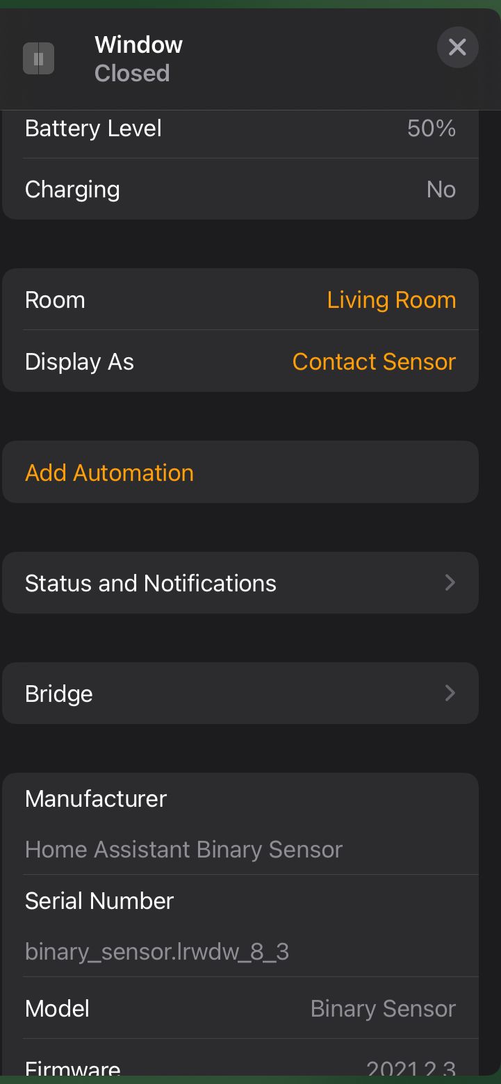
  • @nekitoss If I were you I;d reflash the bootloader and chec again. I got my pro mini with ebyte nrf24 to work and register with the gateway all the way down to 1.63V, so somethingi is wrong if you are loosing it at 2.7V (which is also as it happens, a BoD setting for atmel 328p). For the test I used minicore bootloader iwth Bod disabled and 2MHz clock. Bench power supply for the voltage variation.


  • @nekitoss No problems with alkaline power, 6 - 18 months now on 2xAA down to ca -15c, battery voltage reported ca 2 or 3 times per day.
    I vaguely recall reading an article on lithium and alkaline battery behaviour in extreme cold weather, the alkalines were the better performers.

    Note that the pro-minis here use onboard booster and LDO which provide stable 3.3v all the way down to ca 1.8v battery death, so battery voltage is unrelated to system voltage unlike your setup. They also use rfm69s (433MHz) which are better able to penetrate structural obstacles.
    Bear in mind that if you have comms problems this can substantially reduce battery life as it does not quickly waken, perform the task and go back to deep sleep


  • @mfalkvidd

    Nice job on updating the infor BTW 🙂


  • Adding on to this.. If we use a map function to convert the battery level like this, then it shows up as an attribute in HomeAssistant and Homekit

    Map function works and not the percent. The percent always shows as zero in Homekit.
    Hope this helps someone!

    void battery()
    {
      long batteryMillivolts = hwCPUVoltage();
      int batteryV =batteryMillivolts /1000 + 0.5;
      auto batteryLevel = map(batteryV,EMPTY_BATTERY, FULL_BATTERY, 0, 100);
      if (batteryLevel > 100) 
      {batteryLevel=100;}
    
    #ifdef MY_DEBUG
      Serial.print("Battery voltage: ");
      Serial.print(batteryMillivolts / 1000.0);
      Serial.println("V");
      Serial.print("Battery Level ");
      Serial.print(batteryLevel);
      Serial.println(" %");
    #endif
    
      if (oldBatteryLevel != batteryLevel) {
        sendBatteryLevel(batteryLevel);
        send(msgV.set(batteryV,2));
        oldBatteryLevel = batteryLevel;
      }
    }
    

    ![Home Assistant](812c9e02-8b21-44dc-ab8d-04559bf38462-image.png image url)

    IHomeKit


  • @skywatch Thank you very much! Your advice helped. Not shure what it was on BOTH devices - my mistake or some corruption of fuses/program.
    On first device (where i found problem) - there were different fuse bits (but according to my eyes BOD was even disabed, but not shure). On the second (where i tested) fuses were checked and were correct. I tried to play with fuses and erase chip... and something strange happened - or chip memory was broken or i can't verify program when box "erase flash and eeprom" is checked... so i took fresh nano, programmed it and resoldered MCU into the second device.
    So both devices now are fixed and tested - both work till ~1.9V.
    Thanks, you saved my brains!


  • @nekitoss Yay! 🙂

    Well done on getting it working!


  • Hi from France;
    I've tried everything I could and no way to put My temp. sensor to deep sleep.
    so I went back to the very beginning with a bare Pro-Min 3.3v and I tryed this:


    #include <LowPower.h>
    void setup() {
    pinMode(13, OUTPUT);
    }
    void loop() {
    LowPower.powerDown(SLEEP_8S, ADC_OFF, BOD_OFF);
    digitalWrite(13, HIGH);
    delay(1000);
    digitalWrite(13, LOW);
    }


    My boad is going to sleep;
    YEEEESSS ! the pb is NOT comming from the board itself....eating a bunch ou micro amp;
    Then I've added the minimum requested to make a MySensor extension and I tried this:


    #define MY_RADIO_NRF24 // Choix du module radio
    #define MY_RF24_PA_LEVEL (RF24_PA_HIGH) //CHOIX: RF24_PA_MIN; RF24_PA_LOW; RF24_PA_HIGH; RF24_PA_MAX
    #define RF24_CHANNEL 76
    #define RF24_DATARATE RF24_250KBPS
    #include <MySensors.h>
    #include <LowPower.h>
    void setup() {
    pinMode(13, OUTPUT);
    }
    void loop() {
    LowPower.powerDown(SLEEP_8S, ADC_OFF, BOD_OFF);
    digitalWrite(13, HIGH);
    delay(1000);
    digitalWrite(13, LOW);
    }


    The boad stays awaken (4 mA current)
    So may be the problem is comming from LowPower library...
    I tried this minimal prgm recommended in a tutorial, using MySensors library and SLEEP function:


    // Enable and select radio type attached
    #define MY_RADIO_RF24
    #include <MySensors.h>
    uint32_t SLEEP_TIME = 900000; // sleep time between reads (in seconds * 1000 )
    int oldBatteryPcnt = 0;
    #define FULL_BATTERY 3 // 3V for 2xAA alkaline. Adjust if you use a different battery setup.
    void setup()
    {
    }
    void presentation()
    {
    // Send the sketch version information to the gateway and Controller
    sendSketchInfo("Battery Meter", "1.0");
    }
    void loop()
    {
    // get the battery Voltage
    long batteryMillivolts = hwCPUVoltage();
    int batteryPcnt = batteryMillivolts / FULL_BATTERY / 1000.0 * 100 + 0.5;
    if (oldBatteryPcnt != batteryPcnt) {
    sendBatteryLevel(batteryPcnt);
    oldBatteryPcnt = batteryPcnt;
    }
    sleep(SLEEP_TIME);
    }


    NO WAY AGAIN; The board is still eating 4mA all the way long.
    I'm lost !!!! Please HELP ME ....


  • @Gilles-BILLARD Using the lowpower lib and mysensors lib together will probably give conflicts, so you should avoid it. MySensors lib implements the same low power tricks.

    When doing the latest test sketch, are you doing this also with a bare pro-mini 3.3V?
    So not connected to anything, no radio, no sensor?
    Try the same latest sketch, but set everything inside the loop() in comment except the sleep line.


  • Thanks EVB;

    1. Yes; Last test with a bare pro-mini 3.3v
    2. I did that...
    // Enable and select radio type attached
    #define MY_RADIO_RF24
    #include <MySensors.h>
    uint32_t SLEEP_TIME = 900000;  // sleep time between reads (in seconds * 1000 )
    int oldBatteryPcnt = 0;
    #define FULL_BATTERY 3 // 3V for 2xAA alkaline. Adjust if you use a different battery setup.
    void setup()
    {
    }
    void presentation()
    {
      // Send the sketch version information to the gateway and Controller
      sendSketchInfo("Battery Meter", "1.0");
    }
    void loop()
    {
    //    // get the battery Voltage
    //    long batteryMillivolts = hwCPUVoltage();
    //    int batteryPcnt = batteryMillivolts / FULL_BATTERY / 1000.0 * 100 + 0.5;
    //  
    //    if (oldBatteryPcnt != batteryPcnt) {
    //      sendBatteryLevel(batteryPcnt);
    //      oldBatteryPcnt = batteryPcnt;
    //  }
      sleep(SLEEP_TIME);
    }
    

    Again : 4.2mA (no sleep )
    So sad ! 😥


  • @Gilles-BILLARD IT took me some time to work it out and get it working.

    I suggest you install MiniCore library - it is easy to follow simple steps and takes a minute or two.

    Then burn a bootloader into the atmega, I always use 3.3V, disable BoD and 4MHz or 8MHz internal clock. You can use one arduino to program another or just get a USB programmer from your preferred source (about $2).

    Once your pro mini is booeloaded and you have your sketch in installed , remove the Power LED (or the series resistor for the LED) and also remove the voltage regulator (or cut the tracks as shown in the battery powered page).

    You won't get down to <10uA in sleep unless you do all of this.


  • Thanks Skywatch,
    My Pro-Mini boards are comming from Aliexpress, so, I was also thinking about the bootloader... what else ?
    I'll do what you explain ASAP and be back to say what...
    BTW: I already have cut the tracks powering the LED & regulator


  • @skywatch NO WAY ! So bad !
    I burned the MiniCore bootloader quite eazily using a second Pro-Mini loaded with Arduino BootLoader ( juste a file name error; looking for optiboot_flash_atmega328p_UART1_115200_16000000L_B5.hex but only optiboot_flash_atmega328p_UART0_115200_16000000L_B5.hex on the folder, so I just changed 0-->1 in the file name) and the résult was:
    *
    avrdude: Version 6.3-20201216
    Copyright (c) 2000-2005 Brian Dean, http://www.bdmicro.com/
    Copyright (c) 2007-2014 Joerg Wunsch

         System wide configuration file is "C:\Users\billa\AppData\Local\Arduino15\packages\MiniCore\hardware\avr\2.1.0/avrdude.conf"
    
         Using Port                    : COM7
         Using Programmer              : stk500v1
         Overriding Baud Rate          : 19200
         AVR Part                      : ATmega328P
         Chip Erase delay              : 9000 us
         PAGEL                         : PD7
         BS2                           : PC2
         RESET disposition             : dedicated
         RETRY pulse                   : SCK
         serial program mode           : yes
         parallel program mode         : yes
         Timeout                       : 200
         StabDelay                     : 100
         CmdexeDelay                   : 25
         SyncLoops                     : 32
         ByteDelay                     : 0
         PollIndex                     : 3
         PollValue                     : 0x53
         Memory Detail                 :
    
                                  Block Poll               Page                       Polled
           Memory Type Mode Delay Size  Indx Paged  Size   Size #Pages MinW  MaxW   ReadBack
           ----------- ---- ----- ----- ---- ------ ------ ---- ------ ----- ----- ---------
           eeprom        65    20     4    0 no       1024    4      0  3600  3600 0xff 0xff
           flash         65     6   128    0 yes     32768  128    256  4500  4500 0xff 0xff
           lfuse          0     0     0    0 no          1    0      0  4500  4500 0x00 0x00
           hfuse          0     0     0    0 no          1    0      0  4500  4500 0x00 0x00
           efuse          0     0     0    0 no          1    0      0  4500  4500 0x00 0x00
           lock           0     0     0    0 no          1    0      0  4500  4500 0x00 0x00
           calibration    0     0     0    0 no          1    0      0     0     0 0x00 0x00
           signature      0     0     0    0 no          3    0      0     0     0 0x00 0x00
    
         Programmer Type : STK500
         Description     : Atmel STK500 Version 1.x firmware
         Hardware Version: 2
         Firmware Version: 1.18
         Topcard         : Unknown
         Vtarget         : 0.0 V
         Varef           : 0.0 V
         Oscillator      : Off
         SCK period      : 0.1 us
    

    avrdude: AVR device initialized and ready to accept instructions

    Reading | ################################################## | 100% 0.04s

    avrdude: Device signature = 0x1e950f (probably m328p)
    avrdude: NOTE: "flash" memory has been specified, an erase cycle will be performed
    To disable this feature, specify the -D option.
    avrdude: erasing chip
    avrdude: reading input file "C:\Users\billa\AppData\Local\Arduino15\packages\MiniCore\hardware\avr\2.1.0/bootloaders/empty/empty.hex"
    avrdude: writing flash (0 bytes):

    Writing | ################################################## | 100% 0.00s

    avrdude: 0 bytes of flash written
    avrdude: verifying flash memory against C:\Users\billa\AppData\Local\Arduino15\packages\MiniCore\hardware\avr\2.1.0/bootloaders/empty/empty.hex:
    avrdude: load data flash data from input file C:\Users\billa\AppData\Local\Arduino15\packages\MiniCore\hardware\avr\2.1.0/bootloaders/empty/empty.hex:
    avrdude: input file C:\Users\billa\AppData\Local\Arduino15\packages\MiniCore\hardware\avr\2.1.0/bootloaders/empty/empty.hex contains 0 bytes
    avrdude: reading on-chip flash data:

    Reading | ################################################## | 100% -0.00s

    avrdude: verifying ...
    avrdude: 0 bytes of flash verified
    avrdude: reading input file "0x0f"
    avrdude: writing lock (1 bytes):

    Writing | ################################################## | 100% 0.04s

    avrdude: 1 bytes of lock written
    avrdude: verifying lock memory against 0x0f:
    avrdude: load data lock data from input file 0x0f:
    avrdude: input file 0x0f contains 1 bytes
    avrdude: reading on-chip lock data:

    Reading | ################################################## | 100% 0.01s

    avrdude: verifying ...
    avrdude: 1 bytes of lock verified

    avrdude done. Thank you.


    Then I loaded it with Blink demo...
    At this point all's OKay. Both Po-Mini are blinking
    Blink
    Then I've loaded the 2nd with that:

    // Enable and select radio type attached
    #define MY_RADIO_RF24
    #include <MySensors.h>
    uint32_t SLEEP_TIME = 4000;  // sleep time (in seconds * 1000 )
    
    void setup() 
    {
    pinMode(LED_BUILTIN, OUTPUT);
    }
    
    void presentation()
    {  
      sendSketchInfo("Test Prgm", "1.0"); // Send the sketch version information to the gateway and Controller
    }
    void loop()
    {
      digitalWrite(LED_BUILTIN, HIGH);
    delay(1000);
      digitalWrite(LED_BUILTIN, LOW);
    delay(1000);  
      
    sleep(SLEEP_TIME);
    }
    

    and...
    the result is...
    No blinking
    NO BLINK
    (draining more or less 2mA; Varying quickly from 1600uA to 2000uA; I should put a scope probe on that....)


  • Mod

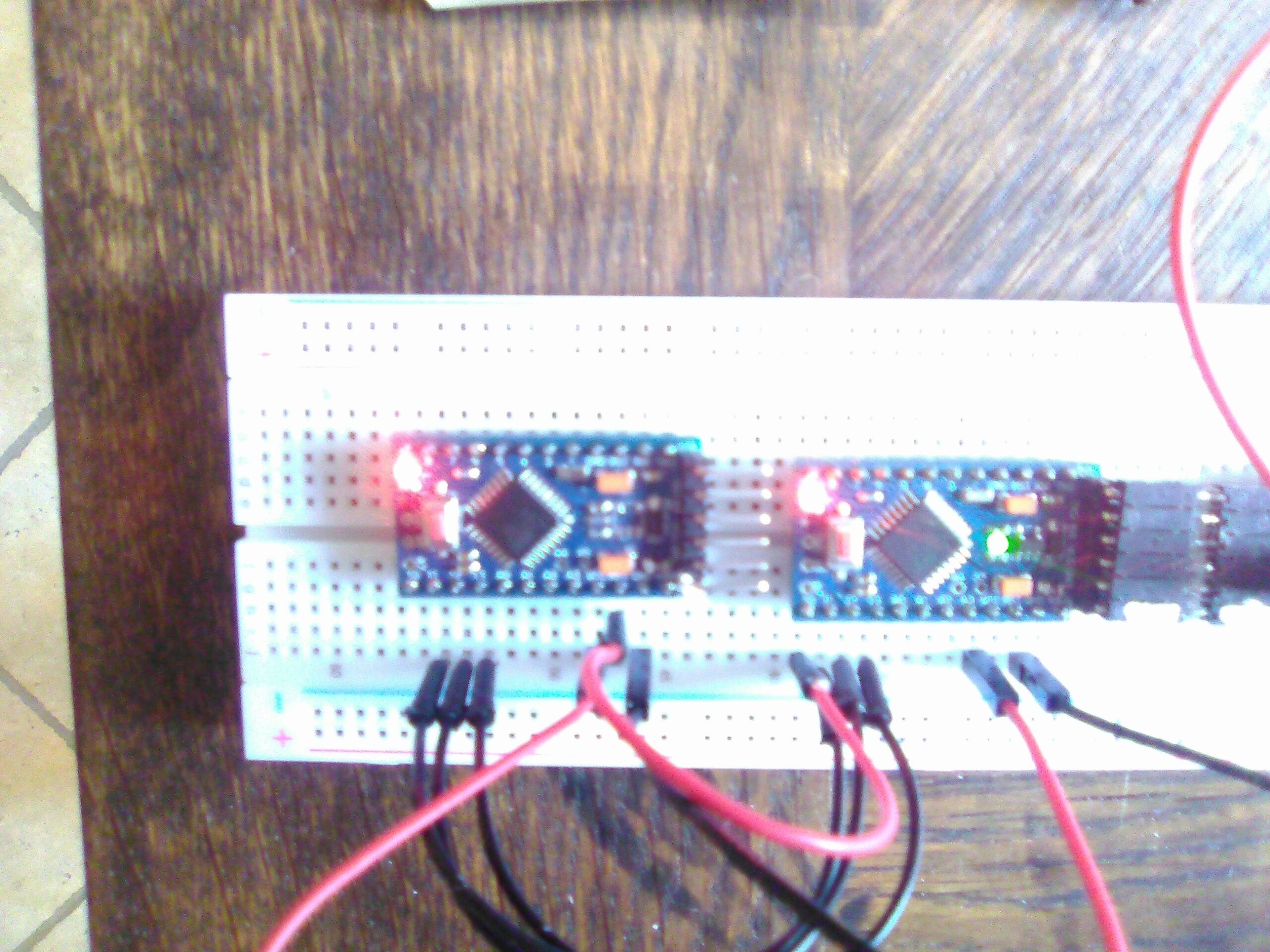
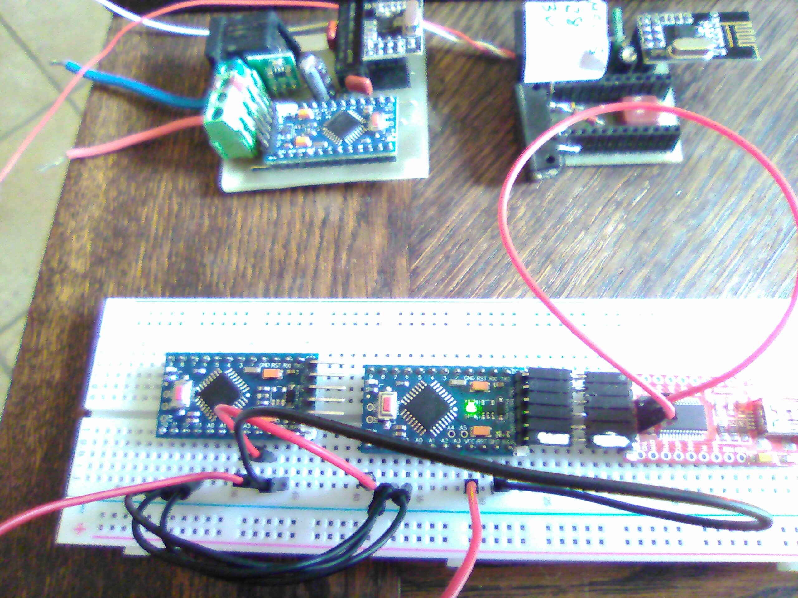
    @Gilles-BILLARD from the photos it seems you didn't connect a radio. If that is the case, the loop will not be entered and your arduino won't sleep!


  • @Yveaux
    YESSSSSS !<
    That was the last problèm to solve.
    Back with my own MySensors routine all is perfect ! (8uA in sleep mode)
    I am very happy now and I thank all those who assisted me.
    You've made my day !
    Gilles


  • @Gilles-BILLARD @Yveaux beat me to it! - But I bet you are a very happy person after that - it is easy when you know how! 🙂


  • @Gilles-BILLARD Damn! Why did I order UNO if I could use another Pro Mini for programming... 🙂


  • @tssk My Pro-Mini's are 3.3V, so this way I avoid the resistors dividers wiring to change 5V (Uno) to 3.3 (Pro-Mini);
    May be you love creating problems where there are none 😉


  • Hy guys; So sorry but the procedure ran just once 😕
    When I reproammed my soldred Pro-Minis (via the radio socket + 1 air wire to the reset pin) none was running as expected; The issue was a kind of permanent reboot..????
    I tried to burn the MinCore bootloader and load my sketch into several brand new boards and the result was the same...
    So I simplified and simplified again the sketches until this one:

    
    /*This sketch is cycling wether you comment MY-DEBUG.....
    SERIAL MONITOR report: 
              2021-04-04 17:20:04.426 Status: MySensors: Node: 20, Sketch Name: Temperature Sensor Test
              2021-04-04 17:20:04.426 Status: MySensors: Node: 20, Sketch Version: G.B.
              2021-04-04 17:20:15.378 (GiBi-Home) Temp (Temptest)
              2021-04-04 17:20:15.368 Status: MySensors: Node: 20, Sketch Name: Temperature Sensor Test
              2021-04-04 17:20:15.368 Status: MySensors: Node: 20, Sketch Version: G.B.
              .
              .
              .
              
    ......or running as it should do if you uncomment MY-DEBUG
    SERIAL MONITOR report: 
              2021-04-04 17:22:52.558 Status: MySensors: Node: 20, Sketch Name: Temperature Sensor Test
              2021-04-04 17:22:52.558 Status: MySensors: Node: 20, Sketch Version: G.B.
              2021-04-04 17:23:02.654 (GiBi-Home) Temp (Temptest)
              2021-04-04 17:23:12.717 (GiBi-Home) Temp (Temptest)
              2021-04-04 17:23:22.781 (GiBi-Home) Temp (Temptest)
              .
              .
              .
    NOTA: wether bootLoader is ordinary AVR bootloader or MiniCore's one
     */
    
    //#define MY_DEBUG 
    
    #define MY_RADIO_RF24
    #include <MySensors.h>  
    
    
    #include <DallasTemperature.h>
    #include <OneWire.h>
    #define ONE_WIRE_BUS 3 // Pin E/S de mesure 
    OneWire oneWire(ONE_WIRE_BUS); // Instanciation du OneWire 
    DallasTemperature sensors(&oneWire); // Passage de l'instance du OneWire à Dallas Temperature.
    
    
    MyMessage msg(0,V_TEMP); // Init temp msg
    
    void before()
    {
        sensors.begin();// démarre le OneWire
    }
    
    void setup()  
    {  
    }
    
    void presentation() 
    {
      sendSketchInfo("Temperature Sensor Test", "GB.1.0");
      present(0, S_TEMP);
    }
    
    void loop()     
    {     
        float (temperature) = sensors.getTempCByIndex(0);   // acquisition du résultat
        temperature = float(int(temperature * 10)) / 10;    // cast pour 1 seul chiffre après la virgule
        send(msg.setSensor(0).set(temperature,1)); 
        sensors.requestTemperatures(); // ordre de mesure  
        // ************Sleeping test ***************
        #ifdef MY_DEBUG 
            delay(10000); // 10 secondes
        #else
            sleep(10000);
        #endif    
    }
    

    and then this one

    // Simplest test to to highlight my problèm
    // Ordinary delay function used on DEBUG
    // Sleep is used without DEBUG
    // Successiv Serial prints should be printed if loop entered
    //************************************************
    /*
     Without DEBUG Serial monitor screen copy
     
     ⸮⸮ `_⸮       ⸮ߟ⸮
    ⸮  ⸮o  ⸮⸮   ⸮/ _⸮⸮⸮` ⸮⸮⸮ ⸮ ⸮⸮ `ߟ⸮  ⸮⸮⸮  ⸮ ⸮⸮`⸮⸮⸮
    ⸮ ⸮⸮/⸮ ⸮ ⸮ ⸮ ⸮_⸮⸮ ⸮ / ⸮ ⸮ `⸮ ⸮/ ⸮⸮⸮/ ⸮`⸮⸮ ⸮⸮⸮/ ⸮⸮⸮
    ⸮ ⸮  ⸮`⸮ ⸮⸮⸮ ⸮⸮⸮⸮⸮ ⸮  ⸮⸮/`⸮ ⸮ ⸮⸮⸮ ⸮ `⸮  ⸮ ⸮ `⸮⸮⸮`⸮
    ⸮⸮⸮  ⸮_⸮⸮⸮⸮, |⸮_⸮⸮/ ⸮⸮ߟ⸮⸮⸮ ⸮⸮⸮_⸮⸮/⸮⸮⸮_/⸮⸮⸮  ⸮⸮⸮⸮/
            ⸮⸮ߟ/`                    `2.3.2
    
    ⸮é⸮u⸮ ⸮⸮ ⸮⸮⸮⸮
    :. 
     ⸮⸮  ⸮⸮       ⸮ߟ⸮
    ⸮  ⸮/  ⸮⸮   ⸮/ ⸮⸮⸮⸮  ⸮⸮⸮ ⸮ ⸮⸮  ߟ⸮  ⸮⸮⸮  ⸮ ⸮⸮ ⸮_⸮
    ⸮ ⸮⸮/⸮ ⸮ ⸮`⸮ ܟ⸮⸮ ⸮ / ⸮ ⸮ ⸮⸮`⸮/`⸮⸮⸮/ ⸮ ⸮⸮ ⸮ߟ/ ⸮⸮⸮
    ⸮`⸮ `⸮`⸮ ⸮⸮⸮ ⸮⸮⸮⸮⸮ ⸮ `ߟ/ ⸮`⸮`ܟ⸮ ⸮ `⸮` ⸮ ⸮  ܟ⸮ ⸮
    ⸮⸮⸮ `⸮⸮⸮⸮⸮⸮, ⸮⸮⸮⸮⸮/ ⸮⸮ߟ⸮⸮⸮ ⸮⸮⸮⸮ߟ/ܟ⸮⸮o⸮⸮⸮` ⸮⸮⸮⸮o
     `  ` ` ⸮⸮ߟo`` `  `  `  ``        2.3.2
    
    ⸮⸮i⸮⸮⸮`⸮⸮`⸮⸮⸮⸮
    :. 
     ⸮⸮  ⸮⸮       ⸮⸮⸮⸮
    ⸮  ⸮/` ⸮⸮ ` ⸮/ ⸮ߟ⸮  ⸮⸮⸮`⸮ ߟ `⸮ߟ `⸮⸮⸮ `⸮`⸮⸮ ⸮ߟ
    ⸮ ⸮⸮/⸮ ⸮ ⸮ ⸮ ⸮ߟ⸮ ⸮ / ⸮ ⸮ ⸮⸮ ⸮o`ߟ⸮/`⸮`⸮⸮ ⸮ߟo ⸮⸮⸮
    ⸮`⸮  ⸮ ⸮ ⸮⸮⸮ ⸮_⸮⸮⸮`⸮``⸮⸮/`⸮ ⸮ ⸮⸮⸮ ⸮ `⸮` ⸮`⸮ `⸮ߟ`⸮
    ⸮⸮⸮` ⸮⸮⸮⸮ߟl`⸮⸮⸮⸮⸮o`⸮ߟ⸮⸮⸮⸮ ⸮⸮⸮ߟ⸮/⸮⸮⸮⸮o⸮⸮⸮ `⸮⸮⸮⸮/
     `      ⸮⸮⸮⸮/   `   ``` ```        2.3.r
    
    etc....
    *******************************************************
    * With DEBUG Serial monitor screen copy
     
     ⸮⸮  ⸮⸮       ⸮⸮⸮⸮
    ⸮  ⸮/  ⸮⸮`  ⸮/ ⸮⸮⸮⸮  ߟ⸮`⸮ ⸮⸮` ⸮⸮⸮  ߟ⸮` ⸮ ⸮⸮`⸮⸮⸮
    ⸮ ⸮⸮o⸮ ⸮ ⸮ ⸮ ⸮_⸮⸮ \ / ⸮ ⸮ ⸮_ ⸮/ ⸮⸮⸮/ ⸮ ⸮| ⸮⸮⸮o ⸮⸮⸮
    ⸮ ⸮` ⸮`⸮ ⸮⸮⸮ ⸮⸮_⸮⸮ ⸮  ⸮⸮/ ⸮ ⸮ ⸮⸮⸮`⸮  ⸮ `⸮`⸮` ⸮ߟ ⸮
    ⸮⸮⸮` ⸮⸮⸮ܟ⸮,`⸮⸮ߟ⸮o ⸮ߟ⸮⸮⸮⸮`⸮⸮⸮⸮⸮⸮/\⸮⸮⸮o⸮⸮⸮` ⸮ߟ⸮/
            ⸮ߟ⸮/ ` ` `                2.3.2
    
    16 ̓⸮:⸮⸮⸮:⸮Ή⸮`⸮⸮⸮⸮,⸮⸮=⸮Ύ΁---,⸮Q=8,⸮⸮⸮=2u5,⸮E⸮=2.3.2
    28 ⸮⸮⸮:⸮⸮⸮⸮
    28 T⸮⸮:⸮⸮⸮:⸮⸮=0
    s6`⸮⸮⸮:⸮Ή⸮:⸮Ӑ ⸮⸮
    38`⸮⸮⸮:⸮I⸮:⸮K,⸮D=25
    40 ⸮⸮⸮z⸮Ё⸮
    45 ?⸮⸮⸮z⸮⸮⸮:⸮⸮⸮⸮,25-25-255-255,⸮=255,⸮=3,⸮=7,⸮t=0,l=0,⸮⸮}0l⸮⸮}0,⸮⸮=⸮⸮:
    10t0`ԓ⸮:⸮⸮⸮:⸮⸮⸮⸮,0-0-25,⸮=255,⸮}3,⸮=x,⸮⸮=1,⸮=1,sg=0:0
    1046 T⸮⸮:⸮⸮⸮:⸮⸮⸮R ⸮⸮,Ʉ=0,⸮=1
    20u4 ⸮⸮⸮:⸮Ё⸮zϋ
    2054 ⸮S⸮:⸮⸮
    2056 ⸮⸮⸮:⸮⸮:⸮⸮
    2058 ԓ⸮:⸮Ќ
    2064 ⸮⸮⸮:⸮⸮⸮:⸮⸮⸮⸮,25-25-0-0,⸮=255l⸮=s,⸮}24l⸮⸮=1,⸮=q,⸮⸮=0,⸮⸮=0l⸮⸮=⸮⸮:1
    2076 ⸮⸮⸮:⸮S⸮:⸮⸮⸮⸮,0-0-25,⸮=255l⸮=3,⸮=25,⸮⸮=1,⸮=1,⸮⸮=0:1
    2082 ⸮S⸮:⸮⸮⸮:⸮⸮⸮⸮ ⸮⸮C⸮,H⸮=1
    2084 ⸮⸮⸮zՐ⸮z⸮⸮
    2086 ⸮⸮⸮:⸮⸮⸮ę:⸮⸮=25,⸮⸮⸮=0,⸮⸮⸮=1
    2099 ⸮⸮⸮:⸮⸮⸮:⸮⸮⸮⸮,25-25-0-0,⸮=255,⸮=3,t=15,⸮⸮=6,⸮=2,⸮⸮=0,⸮⸮=0,⸮⸮=⸮⸮:0100
    2107 ⸮S⸮:⸮Ӈ:⸮Ł⸮,0-0-25,⸮=255,⸮=3,⸮=q5,⸮⸮}6l⸮}2,⸮⸮}0z0q00
    2117 ⸮⸮⸮:⸮Ӈ:⸮Ŏ⸮,ru-25-0m0,⸮=255,⸮=0,⸮=17,⸮⸮=0,⸮}5,⸮⸮}p,⸮⸮=p,⸮⸮}⸮⸮:2.3.2
    21r9 ⸮⸮⸮:⸮⸮⸮:⸮⸮⸮⸮,25-25-0-0,⸮=255,⸮=3,⸮=6,⸮⸮=1,⸮=1,⸮⸮}0,⸮⸮=0l⸮⸮=⸮⸮:p
    2142 ⸮⸮⸮:M⸮⸮:⸮E⸮⸮,p-p-25,⸮=255,⸮}sl⸮}vl⸮⸮}0,⸮=1,s⸮=0:⸮
    2154 ⸮⸮⸮:⸮⸮⸮:⸮⸮⸮⸮,25-25-0-0,⸮=r55,⸮=3,⸮=11,⸮⸮=0,⸮}9,⸮⸮=0l⸮⸮=0,⸮⸮}⸮⸮z⸮⸮⸮⸮ ⸮⸮⸮⸮
    r1v6 ⸮⸮⸮:⸮⸮⸮:⸮⸮⸮⸮,25m25-0-0l⸮=r55,⸮=3,⸮=12,pt=0,⸮}6l⸮⸮=p,⸮⸮=0,⸮⸮=⸮⸮:⸮⸮.2np
    217t ̓⸮z⸮⸮⸮:⸮⸮Q
    2179 ⸮⸮⸮:M⸮⸮:⸮⸮⸮⸮,25-25-0-0,⸮=255,⸮=3,⸮=26,⸮⸮=1,l=1,⸮⸮=0,⸮⸮=0,⸮⸮}ϋ:2
    2187 ԓ⸮:͓⸮:⸮Ł⸮,p-0m2u,⸮=25u,⸮}3,⸮=27l⸮⸮=1,l=1,⸮⸮=0z1
    r1ys ⸮⸮⸮:Љ⸮z⸮⸮ą`⸮Ň=q
    2q97`⸮⸮⸮:⸮G⸮:⸮T⸮
    ⸮⸮)⸮⸮⸮ ⸮⸮ ⸮⸮⸮⸮
    2199 ̓⸮z‡⸮:⸮⸮⸮T ⸮⸮,⸮⸮⸮=1
    :.:.:.:.:.:.:.:.:.:.:.:.:.:.:.:.:.:.:.:.:.
     */
    
    #define MY_DEBUG 
    #define MY_RADIO_RF24
    #include <MySensors.h>
    #include <DallasTemperature.h>
    #include <OneWire.h>
    
    void setup() 
    {
      Serial.begin(115200);                 
      Serial.println ("Début du test"); 
    }
    
    void presentation()
    {  
      sendSketchInfo("Test Prgm", "GB.2.0"); // Send the sketch version information to the gateway and Controller
    }
    void loop()
    { 
    Serial.print (":.");   
    #ifdef MY_DEBUG 
            delay(10000); // 10 secondes
    #else
            sleep(10000);
    #endif    
    }
    

    I have included the Domoticz log in the 1st one and the serial monitor report for the 2nd.

    You can see, if "delay(xxx)" is in use, all's Okay, but if "sleep(xxx) is employed, the sketch is cycling in both sketches....
    What is happening?

    Prog.setup

    Test setup


  • Mod

    @Gilles-BILLARD what pro minis are you using? The 3v3 version only goes to 57600 baud, so 115200 is likely too much


  • @Yveaux Yes Yveaux, you're probably righ, but, if I use AVR bootloader and Test Nb 2 the serial monitor says:

     
     __  __       ____
    |  \/  |_   _/ ___|  ___ _ __  ___  ___  _ __ ___
    | |\/| | | | \___ \ / _ \ `_ \/ __|/ _ \| `__/ __|
    | |  | | |_| |___| |  __/ | | \__ \  _  | |  \__ \
    |_|  |_|\__, |____/ \___|_| |_|___/\___/|_|  |___/
            |___/                      2.3.2
    
    16 MCO:BGN:INIT NODE,CP=RNNNA---,FQ=8,REL=255,VER=2.3.2
    28 TSM:INIT
    28 TSF:WUR:MS=0
    36 TSM:INIT:TSP OK
    38 TSF:SID:OK,ID=20
    40 TSM:FPAR
    45 ?TSF:MSG:SEND,20-20-255-255,s=255,c=3,t=7,pt=0,l=0,sg=0,ft=0,st=OK:
    657 TSF:MSG:READ,0-0-20,s=255,c=3,t=8,pt=1,l=1,sg=0:0
    663 TSF:MSG:FPAR OK,ID=0,D=1
    2054 TSM:FPAR:OK
    2054 TSM:ID
    2056 TSM:ID:OK
    2058 TSM:UPL
    2062 TSF:MSG:SEND,20-20-0-0,s=255,c=3,t=24,pt=1,l=1,sg=0,ft=0,st=OK:1
    2070 TSF:MSG:READ,0-0-20,s=255,c=3,t=25,pt=1,l=1,sg=0:1
    2076 TSF:MSG:PONG RECV,HP=1
    2080 TSM:UPL:OK
    2082 TSM:READY:ID=20,PAR=0,DIS=1
    2086 TSF:MSG:SEND,20-20-0-0,s=255,c=3,t=15,pt=6,l=2,sg=0,ft=0,st=OK:0100
    2095 TSF:MSG:READ,0-0-20,s=255,c=3,t=15,pt=6,l=2,sg=0:0100
    2105 TSF:MSG:SEND,20-20-0-0,s=255,c=0,t=17,pt=0,l=5,sg=0,ft=0,st=OK:2.3.2
    2115 TSF:MSG:SEND,20-20-0-0,s=255,c=3,t=6,pt=1,l=1,sg=0,ft=0,st=OK:0
    2125 TSF:MSG:READ,0-0-20,s=255,c=3,t=6,pt=0,l=1,sg=0:M
    2134 TSF:MSG:SEND,20-20-0-0,s=255,c=3,t=11,pt=0,l=9,sg=0,ft=0,st=OK:Test Prgm
    2146 TSF:MSG:SEND,20-20-0-0,s=255,c=3,t=12,pt=0,l=6,sg=0,ft=0,st=OK:GB.2.0
    2154 MCO:REG:REQ
    2156 TSF:MSG:SEND,20-20-0-0,s=255,c=3,t=26,pt=1,l=1,sg=0,ft=0,st=OK:2
    2164 TSF:MSG:READ,0-0-20,s=255,c=3,t=27,pt=1,l=1,sg=0:1
    2170 MCO:PIM:NODE REG=1
    2174 MCO:BGN:STP
    Début du test
    2177 MCO:BGN:INIT OK,TSP=1
    :.:.:.:.:.:.:.:.:.:.:.:.:.:.:. 
    

    and Domoticz log is:

    2021-04-08 08:08:24.328 Status: MySensors: Node: 20, Sketch Name: Test Prgm
    2021-04-08 08:08:24.329 Status: MySensors: Node: 20, Sketch Version: GB.2.0
    

    NB: On the Sérial monitor, only the last line matters

    One more point: Once the Pro-Minis are burnt with MiniCore library, I'm not able to revert on standard AVR bootloader; They are somehow bricked on MiniCore bootloader


  • @Gilles-BILLARD
    Update: Today, using Arduino UNO as ISP (instead of a ProMini as ISP), I was able to "unbrick" one Pro-Mini and revert to standard AVR bootloader


  • @Gilles-BILLARD Something is not right with either your set up (wiring etc), settings or installation of arduino IDE/libraries.

    I just tested a 3V pro mini and was able to to back and forth freely between MiniCore and AVR bootloaders without issue. Two blinks for Minicore and one blink for AVR.

    A USB programmer is usually cheaper than an uno, so why not try one and see. That is what I use and the only difference is less cabling and only one arduino in the mix.

    In one photo you show nrf24 - are you using FOTA? Is this connected when bootloading the chip?

    The error you described a week ago about optiboot should not happen and you should not need to change anything. Try reinstalling the MiniCore library again following the instructions to the letter. Have you in any way modified your boards.txt or changed your arduino ide from default settings or installation path in any way?


  • @skywatch When I try to use the red ISP (based on a FT232R ) you can see on the pictures I joined, I receive an error msg like :

    avrdude: Version 6.3-20201216
             Copyright (c) 2000-2005 Brian Dean, http://www.bdmicro.com/
             Copyright (c) 2007-2014 Joerg Wunsch
    
             System wide configuration file is "C:\Users\billa\AppData\Local\Arduino15\packages\MiniCore\hardware\avr\2.1.1/avrdude.conf"
    
             Using Port                    : usb
             Using Programmer              : usbasp
    avrdude: error: could not find USB device with vid=0x16c0 pid=0x5dc vendor='www.fischl.de' product='USBasp'
    
    avrdude done.  Thank you
    

    That is the reason why I used or Po-Mini Or UNO as ISP.
    I tried to change and test many others drivers for my FTDI (for 2 days) unsuccessfully

    are you using FOTA? Is this connected when bootloading the chip? As you can see on one picture, in the programming section, NRF is NOT wired to the programmed Pro-Mini.
    Neither it was when I tried to reprogram the wired Pro-mini because I was using the NRF socket to acces the Arduino pins.

    .....or installation of arduino IDE/libraries I checked that as well and installed the new Adruino IDE 2.0.0 beta.... same problèms :-//


  • @skywatch said in 💬 Battery Powered Sensors:

    ....... Two blinks for Minicore and one blink for AVR.....>

    Thay is not my case; 1 blink for AVR and NO BLINK for MiniCore !?!?!?


  • @Gilles-BILLARD Now it is OKay with that blinks; 1 for AVR boot and 2 for MiniCore and I can revert from one to the other and vice-versa.
    ( I removed all concerning MiniCore and reload it )
    But sleep() is still giving the same issue


  • @Gilles-BILLARD You remembered to connect the nrf before going to sleep?


  • skywatch: You remembered to connect the nrf before going to sleep?
    @skywatch Yes, of course;
    I'm 67, retired, and after 9 days (part time) on this issue, I give up !
    I am therefore torn between crushing all that stuff between between a big hammer and my anvil or to discard everything to the trash can.
    These sensors are useless if consuming 20mA H24-7/7 because they they should normally be used outside (in my greenhouses) powered by a battery 18650 + a solar cell.


  • Can anyone let me know if he sees something wrong in that log after a Min-Core bootloader burn in a Pro-Mini 3.3v
    (I do not!)
    I ask because it not the same file as the 1st one (the 1st was including the nb "115200" (bauds?) and now it is "38400" )
    NOTA: Directory is this one:

    C:\Users\billa\AppData\Local\Arduino15\packages\MiniCore\hardware\avr\2.1.1\bootloaders\optiboot_flash\bootloaders\atmega328p\8000000L
    
    
    avrdude: Version 6.3-20201216
             Copyright (c) 2000-2005 Brian Dean, http://www.bdmicro.com/
             Copyright (c) 2007-2014 Joerg Wunsch
    
             System wide configuration file is "C:\Users\billa\AppData\Local\Arduino15\packages\MiniCore\hardware\avr\2.1.1/avrdude.conf"
    
             Using Port                    : COM8
             Using Programmer              : stk500v1
             Overriding Baud Rate          : 19200
             AVR Part                      : ATmega328P
             Chip Erase delay              : 9000 us
             PAGEL                         : PD7
             BS2                           : PC2
             RESET disposition             : dedicated
             RETRY pulse                   : SCK
             serial program mode           : yes
             parallel program mode         : yes
             Timeout                       : 200
             StabDelay                     : 100
             CmdexeDelay                   : 25
             SyncLoops                     : 32
             ByteDelay                     : 0
             PollIndex                     : 3
             PollValue                     : 0x53
             Memory Detail                 :
    
                                      Block Poll               Page                       Polled
               Memory Type Mode Delay Size  Indx Paged  Size   Size #Pages MinW  MaxW   ReadBack
               ----------- ---- ----- ----- ---- ------ ------ ---- ------ ----- ----- ---------
               eeprom        65    20     4    0 no       1024    4      0  3600  3600 0xff 0xff
               flash         65     6   128    0 yes     32768  128    256  4500  4500 0xff 0xff
               lfuse          0     0     0    0 no          1    0      0  4500  4500 0x00 0x00
               hfuse          0     0     0    0 no          1    0      0  4500  4500 0x00 0x00
               efuse          0     0     0    0 no          1    0      0  4500  4500 0x00 0x00
               lock           0     0     0    0 no          1    0      0  4500  4500 0x00 0x00
               calibration    0     0     0    0 no          1    0      0     0     0 0x00 0x00
               signature      0     0     0    0 no          3    0      0     0     0 0x00 0x00
    
             Programmer Type : STK500
             Description     : Atmel STK500 Version 1.x firmware
             Hardware Version: 2
             Firmware Version: 1.18
             Topcard         : Unknown
             Vtarget         : 0.0 V
             Varef           : 0.0 V
             Oscillator      : Off
             SCK period      : 0.1 us
    
    avrdude: AVR device initialized and ready to accept instructions
    
    Reading | ################################################## | 100% 0.04s
    
    avrdude: Device signature = 0x1e950f (probably m328p)
    avrdude: erasing chip
    avrdude: reading input file "0x3f"
    avrdude: writing lock (1 bytes):
    
    Writing | ################################################## | 100% 0.02s
    
    avrdude: 1 bytes of lock written
    avrdude: verifying lock memory against 0x3f:
    avrdude: load data lock data from input file 0x3f:
    avrdude: input file 0x3f contains 1 bytes
    avrdude: reading on-chip lock data:
    
    Reading | ################################################## | 100% 0.02s
    
    avrdude: verifying ...
    avrdude: 1 bytes of lock verified
    avrdude: reading input file "0b11111111"
    avrdude: writing efuse (1 bytes):
    
    Writing | ################################################## | 100% 0.02s
    
    avrdude: 1 bytes of efuse written
    avrdude: verifying efuse memory against 0b11111111:
    avrdude: load data efuse data from input file 0b11111111:
    avrdude: input file 0b11111111 contains 1 bytes
    avrdude: reading on-chip efuse data:
    
    Reading | ################################################## | 100% 0.02s
    
    avrdude: verifying ...
    avrdude: 1 bytes of efuse verified
    avrdude: reading input file "0b11011110"
    avrdude: writing hfuse (1 bytes):
    
    Writing | ################################################## | 100% 0.02s
    
    avrdude: 1 bytes of hfuse written
    avrdude: verifying hfuse memory against 0b11011110:
    avrdude: load data hfuse data from input file 0b11011110:
    avrdude: input file 0b11011110 contains 1 bytes
    avrdude: reading on-chip hfuse data:
    
    Reading | ################################################## | 100% 0.02s
    
    avrdude: verifying ...
    avrdude: 1 bytes of hfuse verified
    avrdude: reading input file "0xe2"
    avrdude: writing lfuse (1 bytes):
    
    Writing | ################################################## | 100% 0.02s
    
    avrdude: 1 bytes of lfuse written
    avrdude: verifying lfuse memory against 0xe2:
    avrdude: load data lfuse data from input file 0xe2:
    avrdude: input file 0xe2 contains 1 bytes
    avrdude: reading on-chip lfuse data:
    
    Reading | ################################################## | 100% 0.01s
    
    avrdude: verifying ...
    avrdude: 1 bytes of lfuse verified
    
    avrdude done.  Thank you.
    
    
    avrdude: Version 6.3-20201216
             Copyright (c) 2000-2005 Brian Dean, http://www.bdmicro.com/
             Copyright (c) 2007-2014 Joerg Wunsch
    
             System wide configuration file is "C:\Users\billa\AppData\Local\Arduino15\packages\MiniCore\hardware\avr\2.1.1/avrdude.conf"
    
             Using Port                    : COM8
             Using Programmer              : stk500v1
             Overriding Baud Rate          : 19200
             AVR Part                      : ATmega328P
             Chip Erase delay              : 9000 us
             PAGEL                         : PD7
             BS2                           : PC2
             RESET disposition             : dedicated
             RETRY pulse                   : SCK
             serial program mode           : yes
             parallel program mode         : yes
             Timeout                       : 200
             StabDelay                     : 100
             CmdexeDelay                   : 25
             SyncLoops                     : 32
             ByteDelay                     : 0
             PollIndex                     : 3
             PollValue                     : 0x53
             Memory Detail                 :
    
                                      Block Poll               Page                       Polled
               Memory Type Mode Delay Size  Indx Paged  Size   Size #Pages MinW  MaxW   ReadBack
               ----------- ---- ----- ----- ---- ------ ------ ---- ------ ----- ----- ---------
               eeprom        65    20     4    0 no       1024    4      0  3600  3600 0xff 0xff
               flash         65     6   128    0 yes     32768  128    256  4500  4500 0xff 0xff
               lfuse          0     0     0    0 no          1    0      0  4500  4500 0x00 0x00
               hfuse          0     0     0    0 no          1    0      0  4500  4500 0x00 0x00
               efuse          0     0     0    0 no          1    0      0  4500  4500 0x00 0x00
               lock           0     0     0    0 no          1    0      0  4500  4500 0x00 0x00
               calibration    0     0     0    0 no          1    0      0     0     0 0x00 0x00
               signature      0     0     0    0 no          3    0      0     0     0 0x00 0x00
    
             Programmer Type : STK500
             Description     : Atmel STK500 Version 1.x firmware
             Hardware Version: 2
             Firmware Version: 1.18
             Topcard         : Unknown
             Vtarget         : 0.0 V
             Varef           : 0.0 V
             Oscillator      : Off
             SCK period      : 0.1 us
    
    avrdude: AVR device initialized and ready to accept instructions
    
    Reading | ################################################## | 100% 0.05s
    
    avrdude: Device signature = 0x1e950f (probably m328p)
    avrdude: NOTE: "flash" memory has been specified, an erase cycle will be performed
             To disable this feature, specify the -D option.
    avrdude: erasing chip
    avrdude: reading input file "C:\Users\billa\AppData\Local\Arduino15\packages\MiniCore\hardware\avr\2.1.1/bootloaders/optiboot_flash/bootloaders/atmega328p/8000000L/optiboot_flash_atmega328p_UART0_38400_8000000L_B5.hex"
    avrdude: writing flash (32768 bytes):
    
    Writing | ################################################## | 100% 0.00s
    
    avrdude: 32768 bytes of flash written
    avrdude: verifying flash memory against C:\Users\billa\AppData\Local\Arduino15\packages\MiniCore\hardware\avr\2.1.1/bootloaders/optiboot_flash/bootloaders/atmega328p/8000000L/optiboot_flash_atmega328p_UART0_38400_8000000L_B5.hex:
    avrdude: load data flash data from input file C:\Users\billa\AppData\Local\Arduino15\packages\MiniCore\hardware\avr\2.1.1/bootloaders/optiboot_flash/bootloaders/atmega328p/8000000L/optiboot_flash_atmega328p_UART0_38400_8000000L_B5.hex:
    avrdude: input file C:\Users\billa\AppData\Local\Arduino15\packages\MiniCore\hardware\avr\2.1.1/bootloaders/optiboot_flash/bootloaders/atmega328p/8000000L/optiboot_flash_atmega328p_UART0_38400_8000000L_B5.hex contains 32768 bytes
    avrdude: reading on-chip flash data:
    
    Reading | ################################################## | 100% 0.00s
    
    avrdude: verifying ...
    avrdude: 32768 bytes of flash verified
    avrdude: reading input file "0x0f"
    avrdude: writing lock (1 bytes):
    
    Writing | ################################################## | 100% 0.05s
    
    avrdude: 1 bytes of lock written
    avrdude: verifying lock memory against 0x0f:
    avrdude: load data lock data from input file 0x0f:
    avrdude: input file 0x0f contains 1 bytes
    avrdude: reading on-chip lock data:
    
    Reading | ################################################## | 100% 0.02s
    
    avrdude: verifying ...
    avrdude: 1 bytes of lock verified
    
    avrdude done.  Thank you.


  • @Gilles-BILLARD I understnad your frustration - I have been there myself.

    I suggest s simple node to test with, something like the door/window sensor with just one switch.

    Take your promini, remove leds and power regulator (or cut tracks) then burn MiniCore bootloader with 9600 baud, 3.3V, 8MHz INTERNAL, BoD DISABLED.

    Then add the radio module (you can try another if you have it - what radio modules are you using? - A link or photo might help, there are bad ones and fakes that could be a problem for you). Load your sketch and try again.

    You can measure the current to the whole set up and then just the radio to see if radio is not sleeping. ....


  • @skywatch said in 💬 Battery Powered Sensors:

    I suggest s simple node to test with, something like the door/window sensor with just one switch.

    I'll do that, but for my thermal sensor the test cannot be more simple

    ......burn MiniCore bootloader with 9600 baud, 3.3V, 8MHz INTERNAL, BoD DISABLED.

    I don't have the choice for the baud rate; Where is it located ?

    Then add the radio module (you can try another if you have it

    I swaped everything I could. (The radio modules that was connected to the single functionning sensor included)

    what radio modules are you using? - A link or photo might help, there are bad ones and fakes that could be a problem for you).

    Bought from Aliexpress;

    Load your sketch and try again.

    I have done the whole process hundreds and hundreds of time

    You can measure the current to the whole set up and then just the radio to see if radio is not sleeping. ....

    Yes I'll do that...


  • @Gilles-BILLARD It's in the sketch when you start serial interface. As an aside have you checked the baud rate the pro mini or uno you are using as a programmer - maybe it is 115200 and that is optimistic for a 3.3V board. Make sure the programmer is using 19200 just to be safe.

    For inof I am using arduino ide 1.8.13 and musensors 2.3.2 with a £2 aliexpress serial prgrammer and have only encountered warnings about sck (which can safely be ignored)....


  • @Gilles-BILLARD said in 💬 Battery Powered Sensors:

    Bought from Aliexpress;

    That is not much help.


  • @skywatch said in 💬 Battery Powered Sensors:

    @Gilles-BILLARD It's in the sketch when you start serial interface. As an aside have you checked the baud rate the pro mini or uno you are using as a programmer - maybe it is 115200 and that is optimistic for a 3.3V board. Make sure the programmer is using 19200 just to be safe.

    For inof I am using arduino ide 1.8.13 and musensors 2.3.2 with a £2 aliexpress serial prgrammer and have only encountered warnings about sck (which can safely be ignored)....

    Ha, OKay; I've aslo supposed a pb from that, so I removed the sérial monitor and baud rate config.
    And after the bootlaoder burning, the log is OKay.. the MEGA328P ID is also the good one and always the same for all 328


  • @skywatch said in 💬 Battery Powered Sensors:

    ...........have you checked the baud rate the pro mini or uno you are using as a programmer - maybe it is 115200 and that is optimistic for a 3.3V board.

    The programmer is loaded with standard Arduino ISP sketch (19200 default baud rate)


  • @skywatch said in 💬 Battery Powered Sensors:

    @Gilles-BILLARD I understnad your frustration - I have been there myself.

    I suggest s simple node to test with, something like the door/window sensor with just one switch.

    I did that right away and the result is....
    All's OKay without sleep(xxx):

    2021-04-10 17:38:22.898 Status: MySensors: Node: 52, Sketch Name: Temperature Sensor Sleep
    2021-04-10 17:38:22.899 Status: MySensors: Node: 52, Sketch Version: GB.3.0
    2021-04-10 17:40:25.515 (GiBi-Home) Light/Switch (Security Sensor)
    2021-04-10 17:40:31.277 (GiBi-Home) Light/Switch (Security Sensor)
    

    Présentation then 2 minutes until I change the input twice

    But with sleep() included...

    2021-04-10 17:34:12.251 Status: MySensors: Node: 51, Sketch Name: Temperature Sensor Sleep
    2021-04-10 17:34:12.251 Status: MySensors: Node: 51, Sketch Version: GB.3.0
    2021-04-10 17:34:22.491 (GiBi-Home) Light/Switch (Security Sensor)
    2021-04-10 17:34:22.486 Status: MySensors: Node: 51, Sketch Name: Temperature Sensor Sleep
    2021-04-10 17:34:22.486 Status: MySensors: Node: 51, Sketch Version: GB.3.0
    2021-04-10 17:34:32.561 (GiBi-Home) Light/Switch (Security Sensor)
    2021-04-10 17:34:32.556 Status: MySensors: Node: 51, Sketch Name: Temperature Sensor Sleep
    2021-04-10 17:34:32.556 Status: MySensors: Node: 51, Sketch Version: GB.3.0
    2021-04-10 17:34:42.631 (GiBi-Home) Light/Switch (Security Sensor)
    2021-04-10 17:34:42.626 Status: MySensors: Node: 51, Sketch Name: Temperature Sensor Sleep
    2021-04-10 17:34:42.626 Status: MySensors: Node: 51, Sketch Version: GB.3.0
    2021-04-10 17:34:52.701 (GiBi-Home) Light/Switch (Security Sensor)
    2021-04-10 17:34:52.696 Status: MySensors: Node: 51, Sketch Name: Temperature Sensor Sleep
    2021-04-10 17:34:52.696 Status: MySensors: Node: 51, Sketch Version: GB.3.0
    2021-04-10 17:35:02.772 (GiBi-Home) Light/Switch (Security Sensor)
    2021-04-10 17:35:02.767 Status: MySensors: Node: 51, Sketch Name: Temperature Sensor Sleep
    2021-04-10 17:35:02.767 Status: MySensors: Node: 51, Sketch Version: GB.3.0
    2021-04-10 17:35:12.842 (GiBi-Home) Light/Switch (Security Sensor)
    2021-04-10 17:35:12.837 Status: MySensors: Node: 51, Sketch Name: Temperature Sensor Sleep
    2021-04-10 17:35:12.837 Status: MySensors: Node: 51, Sketch Version: GB.3.0
    2021-04-10 17:35:22.913 (GiBi-Home) Light/Switch (Security Sensor)
    2021-04-10 17:35:22.908 Status: MySensors: Node: 51, Sketch Name: Temperature Sensor Sleep
    2021-04-10 17:35:22.908 Status: MySensors: Node: 51, Sketch Version: GB.3.0
    2021-04-10 17:35:32.984 (GiBi-Home) Light/Switch (Security Sensor)
    2021-04-10 17:35:32.979 Status: MySensors: Node: 51, Sketch Name: Temperature Sensor Sleep
    2021-04-10 17:35:32.980 Status: MySensors: Node: 51, Sketch Version: GB.3.0
    2021-04-10 17:35:43.055 (GiBi-Home) Light/Switch (Security Sensor)
    

    The same kind of reboot up to présentation()

    So sad !
    NOTA: The sketch is the one provided as an example in BinarySwitchSensor.ino sketch
    I've just added sleep( 10000) a the very end.


  • Please, have a look at the time stamps:
    Tests vs sleep time
    More or less 10 seconds if sleep time >= 10 000 ms
    Only a little more than 3 sec if sleep time = 2 000 ms
    Could it help ?


  • @Gilles-BILLARD Inoticed the following in the sketch you posted above...

      // ************Sleeping test ***************
        #ifdef MY_DEBUG 
            delay(10000); // 10 secondes
        #else
            sleep(10000);
        #endif    
    }
    

    Delay should be replaced by Wait in mysensors code to avoid blocking.

    I always went by the old saying that when you are in a hole, stop digging. I have not seen the behaviour you show before. I can only suggest that you run the EEPROMclear sketch (file>examples>mysensors>cleareepromconfig) and try again. Check the voltage to the promini is stable and the radio has the recommended capacitor. You might be surprised at the difference a good clean power supply can make.

    #is the gateway running on the same power supply? IS GW receiving messages? Please provide the FULL debug output on the serial monitor. That snippet doesn't help much.


  • Mod

    @Gilles-BILLARD I would like to think along to help, but lost you many posts back...
    All was ok, so what did you change (and why) and what is the real issue right now?
    And as @skywatch indicates, post the full log, sketch and everything. Don't try to filter information yourself, you might miss something.


  • Finally, I found it….
    A big thank you to all those who helped;
    Here's my report in case it could be usefull to others (so, they will not waste as much time as I did)
    All began with my FTDI refusing to work with the MiniCore library, returning this classic error code: "avrdude: error: could not find USB device with vid-0x16c0 pid-0x5dc vendor'www.fischl.de' product'USBasp' when I wanted to reprogram a ProMini.
    So I opted for programming via another ProMini (Arduino as ISP)
    The first ProMini was able to receive the MiniCore bootloader and then my sketch without any problem, but the followings did’nt....No error message was reported; I spent 9 days trying hundreds of times changing only one thing at a time... unsuccessfully.
    But this morning I tried again using version 2.0.0 of Arduino’s IDE, and here I received an error message; "Impossible to recognize the Arduino as ISP" !!!!
    Eureka.... I had the idea to inject the MiniCore BootLoader + the “Arduino ISP” sketch in the 2nd via the IDE Arduino 1.8.13 and then use this very 2nd one to program others; At that moment, everything became normal; The tests were ok and went to "sleep" so I loaded my sketch and everything is good now.
    So: If you try to use Arduino as ISP with MiniCore Both Arduinos sould have been burnt with MiniCore BootLoader
    Thank you again.

    PS: Could the admin delete all my useless posts ?


  • @Yveaux said in 💬 Battery Powered Sensors:

    .... All was ok, so what did you change (and why)

    A the very beginning, hesitating with the procedure, I've probably burnt the Minicore bootloader in the programming ProMini without noticing it... That's the only explanation I see.


  • Just completed 1 year of operation of a PIR sensor in the house that trigger 100-200 times a day. It is powered by 2xAA batteries and here is a graph of battery level over the year.

    graph.jpg


  • @skywatch If your project is free and open, where i can look at it? At the moment i need to solve same problem. On your graph what will be 0% ? For mine devices it is minimum 1.9v, for few it is 2.2v


  • @nekitoss
    I used 3.3V pro mini with regulator removed and powered by Vin pin. Also removed leds from the pro mini.

    I used minicore bootloader.

    I used the small pir sensors and again removed the regulator to power directly from the pro mini outputs.

    After that sleep the node and trigger on interrupt.

    Send battery level once a day.

    Use inbuilt battery level monitor and not external components that constantly drain power to get battery level.

    1.8V is 0% on the graph (not visible yet!) but I have had nodes working below 1.7V It's a matter of luck with that it seems.

    Hope this helps you on the right track. I'll try and help if you want.

    1ed.jpg

    This is the latest image and still going strong after 18 months. Voltage is at 2.903V

    Here is photo of the test example - I need to make a case and produce more of them over winter.....

    20231016_095845.jpg

    Here is the same build/code of a window sensor. Similar time frame but hardly triggered.....

    2ed.jpg


Log in to reply
 

Suggested Topics

0
Online

11.2k
Users

11.1k
Topics

112.5k
Posts