💬 Soil Moisture Sensor
-
The sketch does not correspond to the sensor shown in the images. It is much better to use the 2-pin sensors and drive them directly using digital outputs. Search for FC28 (better) or YL-69 in ebay or amazon. I use a voltage divider with a 10k resistor
I've been using the alternating polarity approach on about 20 sensors, with perfect results and no signs of corrosion after around 6 months. I run some tests to determine the effect of measuring time and finally came up with 5ms with no averaging. The batteries last for months; I'm not sure how many since I haven't yet had to replace any (status led removed from 3.3v arduino mini pro board).
As a reference, I tested a rain sensor (same principle) with no alternating current and as soon as a drop of water touched the tracks, small bubbles were produced with indicated that electrolysis was taking place. The effect could be seen on the tracks after just a couple of minutes.
I'm attaching my sketch below. It reports battery level in addition to moisture. It uses the development branch of the mysensors library in order to use the new version of the rfm69 drivers with RSSI ATC - which btw works more than perfect.
I'm using Domoticz which includes a predefined device for moisture. This device uses the centibar scale, so I calibrated my sensors in % moisture and then convert to cb.
#define MY_RADIO_RFM69
#define MY_RFM69_NEW_DRIVER   // ATC on RFM69 works only with the new driver (not compatible with old=default driver)
#define MY_IS_RFM69HW
#define MY_RFM69_FREQUENCY RFM69_868MHZ
#define MY_RFM69_ATC_TARGET_RSSI_DBM (-70)
#define MY_RFM69_NETWORKID  100

#define MY_PARENT_NODE_ID 0
#define MY_PARENT_NODE_IS_STATIC
#define MY_TRANSPORT_MAX_TX_FAILURES 3

#define MY_DEBUG

#include <MySensors.h>
#include <SPI.h>
#include <Vcc.h>
#include <Streaming.h>
#include <math.h>

#define VERSION "1.1"
/* Measurement probe connected to pins shown below
I avoided using pins 2 and 3 because they are reserved for IRQ (potential future use) - 2 is also used by the RFM69 module.
Although this may not actually have a noticeable effect, I also avoided 5 and 6 because they support PWM and hence are a bit slower.
*/
#define PIN_ALIM1 4                                   // Connect to input of resistor
#define PIN_ALIM2 7                                   // Connect to input of measuring probe
#define PIN_LECTURA A0

#define AGUA_DIR 780.0
#define AGUA_INV 160.0
#define AIRE_DIR 0.0
#define AIRE_INV 1023.0
#define TIEMPO_LECTURA 5
#define SLEEP_TIME_1h 3132000 // 1 h = 1*60*60000 = 3600000 ms -13% = 3132000 ms(my arduinos show a delay of 8s/min = 13%)
#define SLEEP_TIME_2h 6264000 // 2 h = 2*60*60000 = 7200000 ms -13% = 6264000 ms
#define SLEEP_TIME_3h 9396000 // 3 h = 3*60*60000 = 10800000 ms -13% = 9396000 ms

// Battery calibration (Li-ion)
const float VccMin   = 3.0;                         // Minimum expected Vcc level, in Volts.
const float VccMax   = 4.2;                         // Maximum expected Vcc level, in Volts.
const float VccCorrection = 3.82/3.74;              // Measured Vcc by multimeter divided by reported Vcc

#define CHILD_MOIST_ID 1
MyMessage msgmoist(CHILD_MOIST_ID, V_LEVEL);
Vcc vcc(VccCorrection);

float oldresultcb=0;
int oldbat=0, count=0;

void presentation(){
  Serial.begin(115200);
  sendSketchInfo("Sensor de humedad", VERSION);
  present(CHILD_MOIST_ID, S_MOISTURE, "Humedad suelo");
  analogReference(DEFAULT);
  pinMode(PIN_LECTURA, INPUT);
  pinMode(PIN_ALIM1, OUTPUT);
  pinMode(PIN_ALIM2, OUTPUT);
}

void loop()
{
  unsigned int value1, value2;
  float result1, result2, resultp, resultcb;

//Measurement of moisture
  wait(TIEMPO_LECTURA);
  digitalWrite(PIN_ALIM1, HIGH);
  digitalWrite(PIN_ALIM2, LOW);
  wait(TIEMPO_LECTURA);
  value1=analogRead(PIN_LECTURA);
  result1=constrain(value1/(AGUA_DIR-AIRE_DIR)*100.0, 1, 100);

  digitalWrite(PIN_ALIM1, LOW);
  digitalWrite(PIN_ALIM2, HIGH);
  wait(TIEMPO_LECTURA);
  value2=analogRead(PIN_LECTURA);
  digitalWrite(PIN_ALIM1, LOW);
  digitalWrite(PIN_ALIM2, LOW);
  result2=constrain(100-(value2-AGUA_INV)/(AIRE_INV-AGUA_INV)*100.0,1,100);

/*Conversion from % moisture to cb taken from http://lieth.ucdavis.edu/Research/tens/98/SmtPub.htm
Another option https://www.researchgate.net/figure/260321179_fig1_Fig-1-Relation-curve-between-water-tension-cb-and-soil-moisture-percentage
The scale used in Domoticz is explained here http://www.irrometer.com/basics.html and can be checked in file domoticz/main/RFXNames.cpp
  0-10 Saturated Soil. Occurs for a day or two after irrigation
  10-20 Soil is adequately wet (except coarse sands which are drying out at this range)
  20-60 Usual range to irrigate or water (most soils except heavy clay soils).
  60-100 Usual range to irrigate heavy clay soils
  100-200 Soil is becoming dangerously dry
*/
  resultp=(result1+result2)/2.0;
  resultcb=constrain(square((-2.96699+351.395/resultp)),0,200);                           //Equation fit using stat software
  count++;

//Send the data
  if ((oldresultcb!=resultcb) || (count==4)) send(msgmoist.set((unsigned int)resultcb));

//Measure battery voltage here since it has been under change recently (more reliable)
  float v = vcc.Read_Volts();
  int p = vcc.Read_Perc(VccMin, VccMax);
  p=constrain(p,0,100);
  if ((p!=oldbat) || (count==4)) sendBatteryLevel(p);

//Save the last values and reset the counter
  oldresultcb=resultcb;
  oldbat=p;
  if (count==4) count=0;

#ifdef MY_DEBUG
  Serial << "Value1=" << value1 << " " << result1 << endl << "Value2=" << value2 << " " << result2 << endl << "Result = " << resultp << "% (" << resultcb << "cb)" << endl;
  Serial << "VCC = " << v << " Volts" << endl << "VCC% = " << p << " %" << endl;
#endif

  sleep(SLEEP_TIME_2h, true);
  }
And this is how it looks in Domoticz:

I hope this helps.
@manutremo sensors ordered and I'm looking forward to try it! Just a quick question; where did you connect the resistor? Thanks,
Peter
-
@manutremo sensors ordered and I'm looking forward to try it! Just a quick question; where did you connect the resistor? Thanks,
Peter
@peternilsson75 With the sketch I posted back in May, you just need two pieces of conductive wire. No resistor or amplifier needed. :-)
-
Hey @RobKuipers I am trying to reuse your sketch as a water leakage sensor, but I got stopped at the Header.h file. Can you please share its content?
I am also considering using two pieces of wire (on a ribbon strip though, just to peal isolation at strategic places).
I will use it on battery and I was thinking on measuring every minute or so, and send a heartbeat every half hour/hour with battery status.
Do you have any other tips about converting the sketch to water leak?
Thanks for the sketch btw! -
Hey @RobKuipers I am trying to reuse your sketch as a water leakage sensor, but I got stopped at the Header.h file. Can you please share its content?
I am also considering using two pieces of wire (on a ribbon strip though, just to peal isolation at strategic places).
I will use it on battery and I was thinking on measuring every minute or so, and send a heartbeat every half hour/hour with battery status.
Do you have any other tips about converting the sketch to water leak?
Thanks for the sketch btw!@dakipro the content of header.h is
typedef struct {
int digital_input_a;
int analog_input_a;
int digital_input_b;
int analog_input_b;
int level;
bool connected;
} sensorWiring;
Detecting water leakage I would do exactly as you suggested: if you mean eg. to detect a leaking washing machine, it could be monitored by laying the stripped wires parallel on the bottom of a container or tray and put the machine on top of it.
It should be easy to modify or extend the sketch to implement a binary switch to indicate leakage above a certain moisture threshold.Good luck. Please let us know about your progress.
Rob -
Thanks @RobKuipers , it compiles fine now. I will work on finetuning the code, just to confirm, you attach one wire to the both D4 and A0, and second to D5 and A1 ?
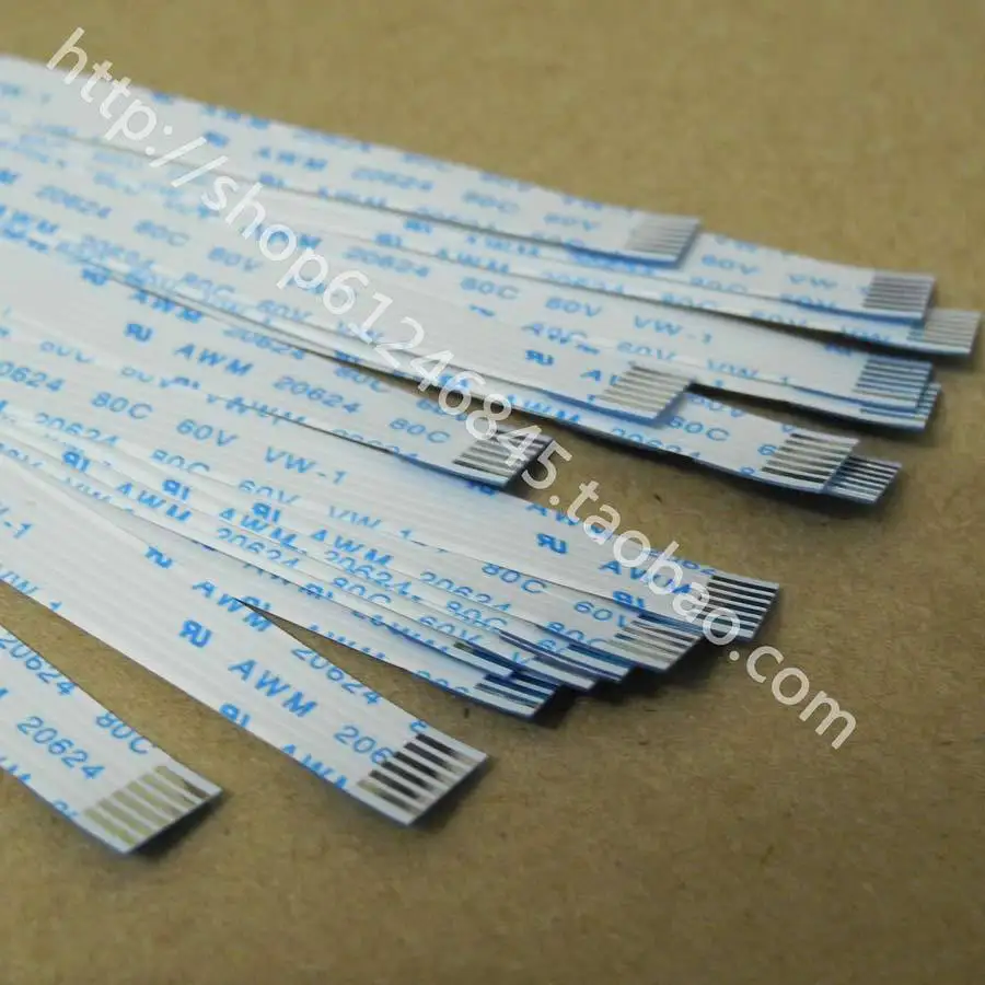
I will test with a variation of this ribbon wire https://ae01.alicdn.com/kf/HTB1admbHVXXXXcfXVXXq6xXFXXXb/NEW-font-b-laptop-b-font-Switch-touchpad-font-b-cable-b-font-1-0mm-pitch.jpg
Just to expose the wire every few cm with a dremel/polisher, and stick the wire to the floor under the appliance somehow (double tape).(for start I will put it under dryer actually, because baby sometimes removes the rubber sealing and it starts leaking)
But I am now being concerned about the corrosion, as it is very thin wire... If it doesn't work long, I will replace it with something more robust and corrosion resistant.
-
Thanks @RobKuipers , it compiles fine now. I will work on finetuning the code, just to confirm, you attach one wire to the both D4 and A0, and second to D5 and A1 ?
I will test with a variation of this ribbon wire https://ae01.alicdn.com/kf/HTB1admbHVXXXXcfXVXXq6xXFXXXb/NEW-font-b-laptop-b-font-Switch-touchpad-font-b-cable-b-font-1-0mm-pitch.jpg
Just to expose the wire every few cm with a dremel/polisher, and stick the wire to the floor under the appliance somehow (double tape).(for start I will put it under dryer actually, because baby sometimes removes the rubber sealing and it starts leaking)
But I am now being concerned about the corrosion, as it is very thin wire... If it doesn't work long, I will replace it with something more robust and corrosion resistant.
@dakipro Good to hear you have it up and running. You are correct about the connections.
Any wire will do, they just have to be close to each other. Enough to bridge the leaking water. As soon as both wires touch the same puddle you will get readings way above zero.
The sketch can do multiple detectors with just one Arduino; so you could could create separate alarms for both the washer and the dryer :-) -
Has anyone had a look at the "Chirp" sensor? It's a great little open hardware project that can be bought on Aliexpress for $4 - $6.

- It monitors the waterlevel and light level.
- When soil moisture is low, it will chirp to let you know it needs water.
- It can be read out via i2c!
-
Has anyone had a look at the "Chirp" sensor? It's a great little open hardware project that can be bought on Aliexpress for $4 - $6.
- It monitors the waterlevel and light level.
- When soil moisture is low, it will chirp to let you know it needs water.
- It can be read out via i2c!
-
Here is the water leakage sensor I was mentioning few posts above, using thin ribbon cable as a sensor.
https://forum.mysensors.org/topic/7736/water-leakage-sensor-using-thin-ribbon-cable-testing-reliability
Time will tell if it is usable at all before it corrodes completely.
Thanks @RobKuipers for the code, works like a charm! -
Just to summarize since the thread is becoming a bit confusing.
The sensor shown in the example and the shopping guide is no more than a device that measures the resistance between the two pins of the fork. That is done by the boards, which includes an analog output and a digital output.
Should you just need to know when moisture is over or below a certain degree, just connect the digital output to a digital pin in the Arduino. Then use the potentiometer in the board to decide the switching point. In a battery powered node, this could be connected to an interrupt pin so the node sleeps and is only waken up when the moisture falls under the predetermined level to send an alert to the controller. But if you want to know track how moisture evolves, you may connect the analog output of the board to an analog pin in the arduino, which will provide a numerical value. Then the sensor needs to be calibrated; there are several forms but one involves measuring the output when the fork is submerged in water (which would be 100% moisture) and then when it's in air (that would be 0%). You can then map this scale to a moisture scale, typically a cb scale.
The negative side of using that board is that the current always flows in the same direction through the fork. The same occurs with another similar type of sensor like the sparkfun here. This will lead in some time to corrosion of the fork, even if it's one of the latest nickeled ones. Reports in the internet vary from weeks to months, but in any case the form will corrode and as a result the measurement will drift slowly.
The alternating polarization strategy tries to overcome this problem. To do so, the board is removed and only the fork is used. Instead of connecting it to Vcc and GND, the two terminals are connected so that the fork is actually one of the resistors in a voltage divider. The other resistor is usually a 10k resistor. In this setup, one of the digital pins is connected to one leg of the resistor, the other resistor leg is connected to one side of the fork, and the other side of the fork is connected to the other digital pin on the Arduino. Another wire needs then to be connected between the connection between the resistor and the fork, to an analog pin of the Arduino, which will read a value that will be proportional to the resistance of the fork, therefore to the moisture level. Then, by switching the pins from INPUT to OUTPUT, and from HIGH to LOW, you can have the current flow in one direction or the opposite one, which significantly delays the corrosion. In my case, the forks still look like new after months of use. Corrosion speed will still obviously depend by time between readings, reading time, soil type and other factors. I've never experimented with this sensor but with a rain sensor I could see corrosion symptoms after some minutes of continuous readings. This sensor also needs to be calibrated in a similar way as the former one. This setup makes the sketch a bit more complex but there are multiple examples here and in the internet.
There are also variations on the measurement strategy within this approach. For example, you may just take a reading in one direction, another reading in the other direction, convert them to moisture level, and average them. Other people take several readings and average them all. I realized that if the reading is repeated, the value increases with each reading until it stabilizes at a certain value, so I decided to have the sketch iterate until two consecutive readings get the same result. The measuring time also needs to be asessed; in my investigation, the shorter the time, the less battery consumption, but at some point around 5ms the readings started to be unreliable. On the other hand, the longer the measurement the more realiable, but the span of the measurements in analog pin where closer and closer which led to loss of accuracy, and of course higher battery consumption. I decided 10ms was a good balance but others' milage may vary.
Finally, there are other completely types of moisture sensor that measure the soil dielectric constant instead of its resistance. They are said to be more reliable, and additionally they do not suffer from corrosion since they do not need to be conductive, hence they are covered by a layer of non-metal material (probably epoxy?). This makes them more durable but also more expensive. I have no experience with those.
I hope this contributes to clarify this topic a little bit. This thread contains additional information on the same topic.
-
I guess I'm not the only one seeking for the correct diagram. It can be found here: http://vanderleevineyard.com/1/post/2012/08/-the-vinduino-project-3-make-a-low-cost-soil-moisture-sensor-reader.html

-
Now that I managed to get my grips on Fritzing, I thought I could share a quick diagram of my own device which I tried to describe above.

Note that the capacitor between the middle point of the voltage divider and GND is just recommended, and its value is orientative.
Not showing battery, radio, reset button, etc., just the soil moisture sensor part.
I've seen other versions using transistors to switch the sensor current, and other variations; I think this is the simplest version of an alternating current sensor and it works very well.
-
Now that I managed to get my grips on Fritzing, I thought I could share a quick diagram of my own device which I tried to describe above.
Note that the capacitor between the middle point of the voltage divider and GND is just recommended, and its value is orientative.
Not showing battery, radio, reset button, etc., just the soil moisture sensor part.
I've seen other versions using transistors to switch the sensor current, and other variations; I think this is the simplest version of an alternating current sensor and it works very well.
@manutremo You may want to put a jumper in on the top power bus that you connect the 100nf capacitor to. It is not clear, at least to me, if that is to VCC or GND. On a true breadboard you would have to do that.
-
@manutremo You may want to put a jumper in on the top power bus that you connect the 100nf capacitor to. It is not clear, at least to me, if that is to VCC or GND. On a true breadboard you would have to do that.
@dbemowsk the convention in these breadboards is that the blue rail is Gnd. You may either connect the two sides or use a Mb102 module to feed both sides at the same time. You may also choose other options.
The capture is not showing the power feed part since it's clear enough and because what it is mainly trying to describe is the moisture measurement part which is the part seemingly causing confusion and the origin of the thread.
-
@dbemowsk the convention in these breadboards is that the blue rail is Gnd. You may either connect the two sides or use a Mb102 module to feed both sides at the same time. You may also choose other options.
The capture is not showing the power feed part since it's clear enough and because what it is mainly trying to describe is the moisture measurement part which is the part seemingly causing confusion and the origin of the thread.
@manutremo said in 💬 Soil Moisture Sensor:
@dbemowsk the convention in these breadboards is that the blue rail is Gnd.
I get that, but if someone were to build that as you have diagrammed with a standard breadboard, it would not work.
@manutremo said in 💬 Soil Moisture Sensor:
You may either connect the two sides or use a Mb102 module to feed both sides at the same time. You may also choose other options.
You, me and other people in here may understand that, but a newbie most likely wouldn't. When I made the comment, I was assuming that that is what you meant, but had to be sure for the newbies.
-
@manutremo said in 💬 Soil Moisture Sensor:
@dbemowsk the convention in these breadboards is that the blue rail is Gnd.
I get that, but if someone were to build that as you have diagrammed with a standard breadboard, it would not work.
@manutremo said in 💬 Soil Moisture Sensor:
You may either connect the two sides or use a Mb102 module to feed both sides at the same time. You may also choose other options.
You, me and other people in here may understand that, but a newbie most likely wouldn't. When I made the comment, I was assuming that that is what you meant, but had to be sure for the newbies.
My posting clearly states:
the capacitor between the middle point of the voltage divider and GND
@dbemowsk said in 💬 Soil Moisture Sensor:
It is not clear, at least to me, if that is to VCC or GND.There's only one cap in the diagram so it should be quite clear.
@dbemowsk
if someone were to build that as you have diagrammed with a standard breadboard, it would not work.I tend to think it wouldn't work with the jumper either if built as diagrammed, since the power source would still be missing.
Don't you think that jumper could possibly lead newbies to confusion into thinking that the power supply needs to be done in a certain way? Or would it be better to avoid overloading the diagram with information irrelevant to the concept being illustrated and just focus on the important part? Certainly a personal decision. I might be wrong but I chose "less is more".
Even newbies getting into electronics understand that diagrams may not always show all the components specially when they are focused and intended to illustrate a specific part of the circuit. even newbies into electronics understand that a power source is always necessary even though it may not appear in the diagram. Almost anyone using a breadboard knows what those rails are, what do the colors mean and that the way to pòwer them is mostly irrelevant as long as they get the proper voltage and current. And for the newbies and the few that may not , the community here will be happy to clarify.
I appreciate your contribution but still fail to see why the diagram is confusing and I still think it responds to its original purpose. Feel free to improve it at your convenience.
-
Try to never try resistive sensors. It is reaaly wrong way. I try to bult few resistive. No way.
I try to buld some inductive. Yes, it's possible, but lot of analog parts, difficult to calibrate. No way too.
Capacitive senors is most reliable and has a simple digital schematics.Good luck you on your way)
PS: here is my own sensor http://vegimatics.com/products/current/
want do discuss - wellcome) -
Try to never try resistive sensors. It is reaaly wrong way. I try to bult few resistive. No way.
I try to buld some inductive. Yes, it's possible, but lot of analog parts, difficult to calibrate. No way too.
Capacitive senors is most reliable and has a simple digital schematics.Good luck you on your way)
PS: here is my own sensor http://vegimatics.com/products/current/
want do discuss - wellcome)
Hello! It looks like you're interested in this conversation, but you don't have an account yet.
Getting fed up of having to scroll through the same posts each visit? When you register for an account, you'll always come back to exactly where you were before, and choose to be notified of new replies (either via email, or push notification). You'll also be able to save bookmarks and upvote posts to show your appreciation to other community members.
With your input, this post could be even better 💗
Register Login