Ethernet gateway with W5100
-
Hello,
I recently decide to have some fun with Arduino and MySensors. I am not a programmer so I don know what exactly I'm doing.
I bought on Ebay an Arduino Shield Compatible (not original, neither only for arduino uno r3) and to be sure an ethernet adapter too.
The arduino shield have a Wiznet W5100 chip (which should be almost compatible with MySensors) and the etherent adapte have an ENC28J60 (which is supported but with some modificantions to the UIPE code).
So, i put my shield on the arduino, in the w5100 gateway script enable the softspi and connected my nrf24... When I go to the serial console, it gave me DHCP Failture (once i got connected, on my router i reserved the ip for the arsuino specific mac address) and assigned a static ip of 192.168.1.35 (the one assigned by my router to the mac address). If I give the ip number in the console says that its connected successfully with that ip, but actually it isn't (if i go to my router it says that it isn't connected and the ip is free), even if i go to Domoticz it can't connect to the gateway, neither MyController (i hope it's spelled correctly).
If i do the same for the ENC driver it works great, it even recognise my node (which is a RelayActuator on a nano) which when is connected through the w5100 doesn't show up in the Serial Console.I leave my codes Here so you can look and eventually tell me what is wrong:
W5100 Code:/** * The MySensors Arduino library handles the wireless radio link and protocol * between your home built sensors/actuators and HA controller of choice. * The sensors forms a self healing radio network with optional repeaters. Each * repeater and gateway builds a routing tables in EEPROM which keeps track of the * network topology allowing messages to be routed to nodes. * * Created by Henrik Ekblad <henrik.ekblad@mysensors.org> * Copyright (C) 2013-2015 Sensnology AB * Full contributor list: https://github.com/mysensors/Arduino/graphs/contributors * * Documentation: http://www.mysensors.org * Support Forum: http://forum.mysensors.org * * This program is free software; you can redistribute it and/or * modify it under the terms of the GNU General Public License * version 2 as published by the Free Software Foundation. * ******************************* * * REVISION HISTORY * Version 1.0 - Henrik EKblad * Contribution by a-lurker and Anticimex, * Contribution by Norbert Truchsess <norbert.truchsess@t-online.de> * Contribution by Tomas Hozza <thozza@gmail.com> * * * DESCRIPTION * The EthernetGateway sends data received from sensors to the ethernet link. * The gateway also accepts input on ethernet interface, which is then sent out to the radio network. * * The GW code is designed for Arduino 328p / 16MHz. ATmega168 does not have enough memory to run this program. * * LED purposes: * - To use the feature, uncomment WITH_LEDS_BLINKING in MyConfig.h * - RX (green) - blink fast on radio message recieved. In inclusion mode will blink fast only on presentation recieved * - TX (yellow) - blink fast on radio message transmitted. In inclusion mode will blink slowly * - ERR (red) - fast blink on error during transmission error or recieve crc error * * See http://www.mysensors.org/build/ethernet_gateway for wiring instructions. * */ // Enable debug prints to serial monitor #define MY_DEBUG // Enable and select radio type attached #define MY_RADIO_NRF24 //#define MY_RADIO_RFM69 // Enable gateway ethernet module type #define MY_GATEWAY_W5100 // W5100 Ethernet module SPI enable (optional if using a shield/module that manages SPI_EN signal) #define MY_W5100_SPI_EN 4 // Enable Soft SPI for NRF radio (note different radio wiring is required) // The W5100 ethernet module seems to have a hard time co-operate with // radio on the same spi bus. #if !defined(MY_W5100_SPI_EN) && !defined(ARDUINO_ARCH_SAMD) #define MY_SOFTSPI #define MY_SOFT_SPI_SCK_PIN 14 #define MY_SOFT_SPI_MISO_PIN 16 #define MY_SOFT_SPI_MOSI_PIN 15 #endif // When W5100 is connected we have to move CE/CSN pins for NRF radio #ifndef MY_RF24_CE_PIN #define MY_RF24_CE_PIN 5 #endif #ifndef MY_RF24_CS_PIN #define MY_RF24_CS_PIN 6 #endif // Enable to UDP #define MY_USE_UDP #define MY_IP_ADDRESS 192,168,1,35 // If this is disabled, DHCP is used to retrieve address // Renewal period if using DHCP #define MY_IP_RENEWAL_INTERVAL 60000 // The port to keep open on node server mode / or port to contact in client mode #define MY_PORT 5003 // Controller ip address. Enables client mode (default is "server" mode). // Also enable this if MY_USE_UDP is used and you want sensor data sent somewhere. //#define MY_CONTROLLER_IP_ADDRESS 192, 168, 178, 254 // The MAC address can be anything you want but should be unique on your network. // Newer boards have a MAC address printed on the underside of the PCB, which you can (optionally) use. // Note that most of the Ardunio examples use "DEAD BEEF FEED" for the MAC address. #define MY_MAC_ADDRESS 0x00, 0xAA, 0xBB, 0xCC, 0xDE, 0x02 // Flash leds on rx/tx/err #define MY_LEDS_BLINKING_FEATURE // Set blinking period #define MY_DEFAULT_LED_BLINK_PERIOD 300 // Enable inclusion mode #define MY_INCLUSION_MODE_FEATURE // Enable Inclusion mode button on gateway #define MY_INCLUSION_BUTTON_FEATURE // Set inclusion mode duration (in seconds) #define MY_INCLUSION_MODE_DURATION 60 // Digital pin used for inclusion mode button #define MY_INCLUSION_MODE_BUTTON_PIN 3 // Uncomment to override default HW configurations //#define MY_DEFAULT_ERR_LED_PIN A0 // Error led pin //#define MY_DEFAULT_RX_LED_PIN A2 // Receive led pin //#define MY_DEFAULT_TX_LED_PIN A1 // the PCB, on board LED #include <SPI.h> #if defined(MY_USE_UDP) #include <EthernetUdp.h> #endif #include <Ethernet.h> #include <MySensors.h> void setup() { } void loop() { }ENC28J60 Code:
#define MY_DEBUG

// Enable and select radio type attached
#define MY_RADIO_NRF24
//#define MY_RADIO_RFM69

// When ENC28J60 is connected we have to move CE/CSN pins for NRF radio
#define MY_RF24_CE_PIN 5
#define MY_RF24_CS_PIN 6

// Enable gateway ethernet module type
#define MY_GATEWAY_ENC28J60

// Gateway IP address
#define MY_IP_ADDRESS 192,168,1,35

// The port to keep open on node server mode / or port to contact in client mode
#define MY_PORT 5003

// Controller ip address. Enables client mode (default is "server" mode).
// Also enable this if MY_USE_UDP is used and you want sensor data sent somewhere.
//#define MY_CONTROLLER_IP_ADDRESS 192, 168, 178, 254

// The MAC address can be anything you want but should be unique on your network.
// Newer boards have a MAC address printed on the underside of the PCB, which you can (optionally) use.
// Note that most of the Ardunio examples use  "DEAD BEEF FEED" for the MAC address.
#define MY_MAC_ADDRESS 0x00, 0xAA, 0xBB, 0xCC, 0xDE, 0x02

// Flash leds on rx/tx/err
#define MY_LEDS_BLINKING_FEATURE
// Set blinking period
#define MY_DEFAULT_LED_BLINK_PERIOD 300

// Enable inclusion mode
#define MY_INCLUSION_MODE_FEATURE
// Enable Inclusion mode button on gateway
#define MY_INCLUSION_BUTTON_FEATURE
// Set inclusion mode duration (in seconds)
#define MY_INCLUSION_MODE_DURATION 60
// Digital pin used for inclusion mode button
#define MY_INCLUSION_MODE_BUTTON_PIN  3

//#define MY_DEFAULT_ERR_LED_PIN 7  // Error led pin
//#define MY_DEFAULT_RX_LED_PIN  8  // Receive led pin
//#define MY_DEFAULT_TX_LED_PIN  9  // the PCB, on board LED

#include <SPI.h>
#include <UIPEthernet.h>
#include <MySensors.h>


void setup()
{
}

void loop() {
}
Sorry for my bad english but it isn't my native language :smile:
You may need to comment out this line. It is preventing soft spi from being enabled
// W5100 Ethernet module SPI enable (optional if using a shield/module that manages SPI_EN signal) #define MY_W5100_SPI_EN 4 -
You may need to comment out this line. It is preventing soft spi from being enabled
// W5100 Ethernet module SPI enable (optional if using a shield/module that manages SPI_EN signal) #define MY_W5100_SPI_EN 4@Boots33 said:
You may need to comment out this line. It is preventing soft spi from being enabled
 // W5100 Ethernet module SPI enable (optional if using a shield/module that manages SPI_EN signal)
 #define MY_W5100_SPI_EN 4
I've tried, moved SI SO SCK from the nrf to the respective analog pins but it won't worked, gave me the same problem
-
Uh. I forgot to mention that the shield with the Ethernet library works perfectly, so it's isn't broken...
-
Uh. I forgot to mention that the shield with the Ethernet library works perfectly, so it's isn't broken...
@Edoardo-Macrì
The example W5100 sketch from the arduino IDE should work without any modifications other than to set the ip address you want to use in the line#define MY_IP_ADDRESS
You have made a few changes to the original sketch
on my W5100 gateway the line below remains commented out
// W5100 Ethernet module SPI enable (optional if using a shield/module that manages SPI_EN signal)
// #define MY_W5100_SPI_EN 4
As does the line
// Enable to UDP
//#define MY_USE_UDP
and if you are using a static address this line remains commented out as well
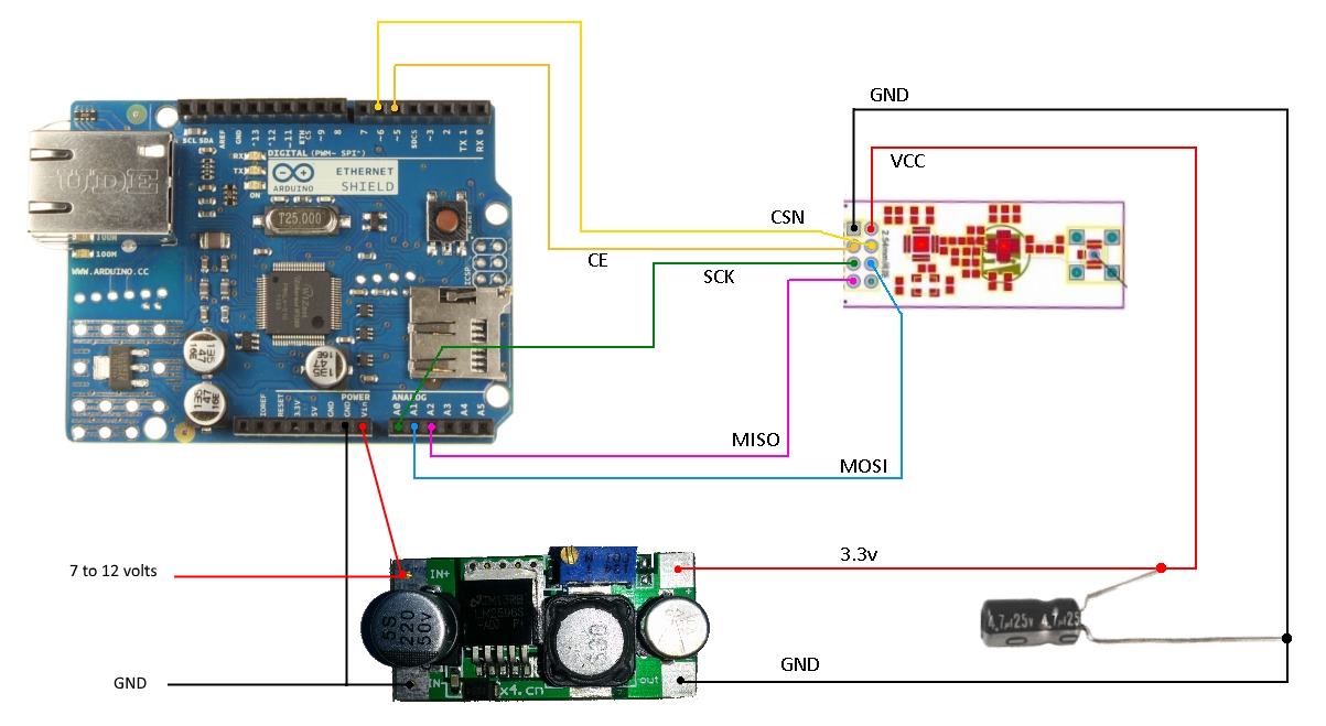
// Renewal period if using DHCP
//#define MY_IP_RENEWAL_INTERVAL 60000
Check your wiring it should be like below. Ignore the extra regulator if not using an amplified radio.
Have you tried to ping the gateway ?
maybe you could post the serial debug info as well, that might give a clue to the problem
People had trouble with some versions of the Arduino IDE causing constant rebooting of the W5100 gateway. See this post
-
@Edoardo-Macrì
The example W5100 sketch from the arduino IDE should work without any modifications other than to set the ip address you want to use in the line#define MY_IP_ADDRESS
You have made a few changes to the original sketch
on my W5100 gateway the line below remains commented out
// W5100 Ethernet module SPI enable (optional if using a shield/module that manages SPI_EN signal)
// #define MY_W5100_SPI_EN 4
As does the line
// Enable to UDP
//#define MY_USE_UDP
and if you are using a static address this line remains commented out as well
// Renewal period if using DHCP
//#define MY_IP_RENEWAL_INTERVAL 60000
Check your wiring it should be like below. Ignore the extra regulator if not using an amplified radio.
Have you tried to ping the gateway ?
maybe you could post the serial debug info as well, that might give a clue to the problem
People had trouble with some versions of the Arduino IDE causing constant rebooting of the W5100 gateway. See this post
@Boots33
Thanks, now it's working.. probably somethin in the DHCP string!This is the working code:
/** * The MySensors Arduino library handles the wireless radio link and protocol * between your home built sensors/actuators and HA controller of choice. * The sensors forms a self healing radio network with optional repeaters. Each * repeater and gateway builds a routing tables in EEPROM which keeps track of the * network topology allowing messages to be routed to nodes. * * Created by Henrik Ekblad <henrik.ekblad@mysensors.org> * Copyright (C) 2013-2015 Sensnology AB * Full contributor list: https://github.com/mysensors/Arduino/graphs/contributors * * Documentation: http://www.mysensors.org * Support Forum: http://forum.mysensors.org * * This program is free software; you can redistribute it and/or * modify it under the terms of the GNU General Public License * version 2 as published by the Free Software Foundation. * ******************************* * * REVISION HISTORY * Version 1.0 - Henrik EKblad * Contribution by a-lurker and Anticimex, * Contribution by Norbert Truchsess <norbert.truchsess@t-online.de> * Contribution by Tomas Hozza <thozza@gmail.com> * * * DESCRIPTION * The EthernetGateway sends data received from sensors to the ethernet link. * The gateway also accepts input on ethernet interface, which is then sent out to the radio network. * * The GW code is designed for Arduino 328p / 16MHz. ATmega168 does not have enough memory to run this program. * * LED purposes: * - To use the feature, uncomment WITH_LEDS_BLINKING in MyConfig.h * - RX (green) - blink fast on radio message recieved. In inclusion mode will blink fast only on presentation recieved * - TX (yellow) - blink fast on radio message transmitted. In inclusion mode will blink slowly * - ERR (red) - fast blink on error during transmission error or recieve crc error * * See http://www.mysensors.org/build/ethernet_gateway for wiring instructions. * */ // Enable debug prints to serial monitor #define MY_DEBUG // Enable and select radio type attached #define MY_RADIO_NRF24 //#define MY_RADIO_RFM69 // Enable gateway ethernet module type #define MY_GATEWAY_W5100 // W5100 Ethernet module SPI enable (optional if using a shield/module that manages SPI_EN signal) //#define MY_W5100_SPI_EN 4 // Enable Soft SPI for NRF radio (note different radio wiring is required) // The W5100 ethernet module seems to have a hard time co-operate with // radio on the same spi bus. #if !defined(MY_W5100_SPI_EN) && !defined(ARDUINO_ARCH_SAMD) #define MY_SOFTSPI #define MY_SOFT_SPI_SCK_PIN 14 #define MY_SOFT_SPI_MISO_PIN 16 #define MY_SOFT_SPI_MOSI_PIN 15 #endif // When W5100 is connected we have to move CE/CSN pins for NRF radio #ifndef MY_RF24_CE_PIN #define MY_RF24_CE_PIN 5 #endif #ifndef MY_RF24_CS_PIN #define MY_RF24_CS_PIN 6 #endif // Enable to UDP //#define MY_USE_UDP #define MY_IP_ADDRESS 192,168,1,35 // If this is disabled, DHCP is used to retrieve address // Renewal period if using DHCP //#define MY_IP_RENEWAL_INTERVAL 60000 // The port to keep open on node server mode / or port to contact in client mode #define MY_PORT 5003 // Controller ip address. Enables client mode (default is "server" mode). // Also enable this if MY_USE_UDP is used and you want sensor data sent somewhere. //#define MY_CONTROLLER_IP_ADDRESS 192, 168, 178, 254 // The MAC address can be anything you want but should be unique on your network. // Newer boards have a MAC address printed on the underside of the PCB, which you can (optionally) use. // Note that most of the Ardunio examples use "DEAD BEEF FEED" for the MAC address. #define MY_MAC_ADDRESS 0x00, 0xAA, 0xBB, 0xCC, 0xDE, 0x02 // Flash leds on rx/tx/err #define MY_LEDS_BLINKING_FEATURE // Set blinking period #define MY_DEFAULT_LED_BLINK_PERIOD 300 // Enable inclusion mode #define MY_INCLUSION_MODE_FEATURE // Enable Inclusion mode button on gateway #define MY_INCLUSION_BUTTON_FEATURE // Set inclusion mode duration (in seconds) #define MY_INCLUSION_MODE_DURATION 60 // Digital pin used for inclusion mode button #define MY_INCLUSION_MODE_BUTTON_PIN 3 // Uncomment to override default HW configurations #define MY_DEFAULT_ERR_LED_PIN A3 // Error led pin #define MY_DEFAULT_RX_LED_PIN A4 // Receive led pin #define MY_DEFAULT_TX_LED_PIN A5 // the PCB, on board LED #include <SPI.h> #if defined(MY_USE_UDP) #include <EthernetUdp.h> #endif #include <Ethernet.h> #include <MySensors.h> void setup() { } void loop() { } -
@Boots33
Thanks, now it's working.. probably somethin in the DHCP string!This is the working code:
/** * The MySensors Arduino library handles the wireless radio link and protocol * between your home built sensors/actuators and HA controller of choice. * The sensors forms a self healing radio network with optional repeaters. Each * repeater and gateway builds a routing tables in EEPROM which keeps track of the * network topology allowing messages to be routed to nodes. * * Created by Henrik Ekblad <henrik.ekblad@mysensors.org> * Copyright (C) 2013-2015 Sensnology AB * Full contributor list: https://github.com/mysensors/Arduino/graphs/contributors * * Documentation: http://www.mysensors.org * Support Forum: http://forum.mysensors.org * * This program is free software; you can redistribute it and/or * modify it under the terms of the GNU General Public License * version 2 as published by the Free Software Foundation. * ******************************* * * REVISION HISTORY * Version 1.0 - Henrik EKblad * Contribution by a-lurker and Anticimex, * Contribution by Norbert Truchsess <norbert.truchsess@t-online.de> * Contribution by Tomas Hozza <thozza@gmail.com> * * * DESCRIPTION * The EthernetGateway sends data received from sensors to the ethernet link. * The gateway also accepts input on ethernet interface, which is then sent out to the radio network. * * The GW code is designed for Arduino 328p / 16MHz. ATmega168 does not have enough memory to run this program. * * LED purposes: * - To use the feature, uncomment WITH_LEDS_BLINKING in MyConfig.h * - RX (green) - blink fast on radio message recieved. In inclusion mode will blink fast only on presentation recieved * - TX (yellow) - blink fast on radio message transmitted. In inclusion mode will blink slowly * - ERR (red) - fast blink on error during transmission error or recieve crc error * * See http://www.mysensors.org/build/ethernet_gateway for wiring instructions. * */ // Enable debug prints to serial monitor #define MY_DEBUG // Enable and select radio type attached #define MY_RADIO_NRF24 //#define MY_RADIO_RFM69 // Enable gateway ethernet module type #define MY_GATEWAY_W5100 // W5100 Ethernet module SPI enable (optional if using a shield/module that manages SPI_EN signal) //#define MY_W5100_SPI_EN 4 // Enable Soft SPI for NRF radio (note different radio wiring is required) // The W5100 ethernet module seems to have a hard time co-operate with // radio on the same spi bus. #if !defined(MY_W5100_SPI_EN) && !defined(ARDUINO_ARCH_SAMD) #define MY_SOFTSPI #define MY_SOFT_SPI_SCK_PIN 14 #define MY_SOFT_SPI_MISO_PIN 16 #define MY_SOFT_SPI_MOSI_PIN 15 #endif // When W5100 is connected we have to move CE/CSN pins for NRF radio #ifndef MY_RF24_CE_PIN #define MY_RF24_CE_PIN 5 #endif #ifndef MY_RF24_CS_PIN #define MY_RF24_CS_PIN 6 #endif // Enable to UDP //#define MY_USE_UDP #define MY_IP_ADDRESS 192,168,1,35 // If this is disabled, DHCP is used to retrieve address // Renewal period if using DHCP //#define MY_IP_RENEWAL_INTERVAL 60000 // The port to keep open on node server mode / or port to contact in client mode #define MY_PORT 5003 // Controller ip address. Enables client mode (default is "server" mode). // Also enable this if MY_USE_UDP is used and you want sensor data sent somewhere. //#define MY_CONTROLLER_IP_ADDRESS 192, 168, 178, 254 // The MAC address can be anything you want but should be unique on your network. // Newer boards have a MAC address printed on the underside of the PCB, which you can (optionally) use. // Note that most of the Ardunio examples use "DEAD BEEF FEED" for the MAC address. #define MY_MAC_ADDRESS 0x00, 0xAA, 0xBB, 0xCC, 0xDE, 0x02 // Flash leds on rx/tx/err #define MY_LEDS_BLINKING_FEATURE // Set blinking period #define MY_DEFAULT_LED_BLINK_PERIOD 300 // Enable inclusion mode #define MY_INCLUSION_MODE_FEATURE // Enable Inclusion mode button on gateway #define MY_INCLUSION_BUTTON_FEATURE // Set inclusion mode duration (in seconds) #define MY_INCLUSION_MODE_DURATION 60 // Digital pin used for inclusion mode button #define MY_INCLUSION_MODE_BUTTON_PIN 3 // Uncomment to override default HW configurations #define MY_DEFAULT_ERR_LED_PIN A3 // Error led pin #define MY_DEFAULT_RX_LED_PIN A4 // Receive led pin #define MY_DEFAULT_TX_LED_PIN A5 // the PCB, on board LED #include <SPI.h> #if defined(MY_USE_UDP) #include <EthernetUdp.h> #endif #include <Ethernet.h> #include <MySensors.h> void setup() { } void loop() { }@Edoardo-Macrì great work!