Minimal design thoughts
-
@tbowmo yup, debugging these things is a pain in the neck - I've been working on the OTA bootloader for a while (mainly optimizing size, speed and additional features). What works best for me, is using debugwire in atmel studio...but sometimes quite cryptic and not straight forward :)
-
Bugger.. DHL tried to deliver the package with PCB's from dirtypcbs, while I was at work today. So they only left me a note, that they couldn't deliver it. Have to wait untill monday, before they will try to deliver it again.. :s
Anyway, I now know that the boards are in DK somewhere :)
The other day I also have received 3 pcs of ATSHA204A (samples). so I can verify that part of the HW design.
And last but not least. I have a uCurrent waiting at the post office, that I can pick up later today.. So I can also start measuring supply currents to the device! :) Hope that I'll get some time to look at that part during the weekend :)
-
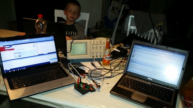
Good news..
On a saturday evening, where nothing is on TV, but a danish pre- european song contest program, I decided that I should have a look at the bootloader (amongst other stuff)
I actually succeeded in getting the bootloader into the device, and I can reprogram using serial now. Next step is to verify that I can use the spi flash to reload the unit.
I have thought of a strategy for testing the flash for reprogramming. It involves making a very basic sketch that I could compile and put into another sketch, which writes the first one to the flash, and reboots the device, and thus reprograms itself with the first sketch :). But it's going to take a while for that to happen (if anyone have a better idea, then please let me know :))
I also have tried the uCurrent, and tried to do some measurements on current consumption. When it's a sleep, it uses arround 60uA, and while awake it's up to 22mA for 60m seconds.
-
That current draw seems a bit high.
A modified 3.3V pro mini draws ~100nA in "deep" sleep without watchdog timer (pretty much everything disabled). The nrf24l01+ draws ~900nA in power down. If you wake up the 328 using its watchdog timer (i.e. sleep != 0), then that watchdog will draw around 5uA, but it wakes up every 8 sec, so the average "extra" current consumption caused by the watchdog is closer to 6uA. According to the si7021 datasheet* it draws 60 nA standby current, and 150 uA active current.
In other words, you should see a current consumption < 10uA in sleep mode. When active, the si7021 is negligible compared to the nrf and 328's current consumption, but the total consumption for nrf and 328 should still be less than 22mA... The 60ms you see probably indicates that the nrf is not able to get a hardware ("link-level") ACK, so it retries up to 15 times. Also, disabling DEBUG in MyConfig.h will save a few extra milliseconds. You should also make sure node.send() is the last thing you do before node.sleep(), or else the NRF will countinue to draw ~13mA until sleep() or RF24::powerDown() is called.This should not be too far from the theoretical current consumption profile for your board when reading hum+temp at given INTERVAL:
(Assuming the nrf, 328 and si7021 has already been "booted")sleep(INTERVAL): ~7uA on average
awake time 2+12+10.8+8 = 32.8ms
- 328 wakeup: 3.6mA for 2ms
- si7021 conversion hum: 3.6mA + 150uA for 12ms
- si7021 conversion temp: 3.6mA + 150uA for 10.8ms
- nrf24 send: 3.6mA + 13.4mA for 8ms (assuming no message retries)What components are actually mounted on the board you tested?
The ATSHA204 should draw max 3mA active, and <150nA sleeping.
The 25aa080sn*- Write current: 3 mA maximum
- Read current: 500uA typical
- Standby current: 500 nA typical
You probably already know all this, but I thought I might mention it anyway :)
http://www.silabs.com/Support Documents/TechnicalDocs/Si7021.pdf
http://www.atmel.com/Images/Atmel-8740-CryptoAuth-ATSHA204-Datasheet.pdf
http://ww1.microchip.com/downloads/en/DeviceDoc/21230E.pdf -
I haven't done anything to optimise things yet. The sketch I'm running is in the examples section on Mysensors github repro so you could have a look there.
The board is without external flash (didn't mount it on board #1 that i used last night) and without atsha204, as it's still the first prototype board. The new version should arrive tomorrow, where I can mount the atsha204.
-
-
forgot an update last week, I received rev2 boards last monday (9/2). but was on vacation with the family (They have priority above "nerd" projects ;))
Will see if I can get a couple of pictures of the new boards when I get home from daytime job today.
And hopefully, I'll get a couple of boards mounted during this week, so I can get it verified, and we can start preparing for "production to the masses" :)
@tbowmo
Nice! I have updated the ATSHA204 personalizer to work without UART and I will try to push it to github tonight or tomorrow so you can use it to verify the ATSAHA (if you need to). I am not completly finished to release signing support to the masses yet, but things are moving along nicely and I hope to be able to do that will full documentation and HW independency by the end of the month.Do you feel secure today? No? Start requiring some signatures and feel better tomorrow ;)
-
@tbowmo
Nice! I have updated the ATSHA204 personalizer to work without UART and I will try to push it to github tonight or tomorrow so you can use it to verify the ATSAHA (if you need to). I am not completly finished to release signing support to the masses yet, but things are moving along nicely and I hope to be able to do that will full documentation and HW independency by the end of the month.Nice! I have updated the ATSHA204 personalizer to work without UART and I will try to push it to github tonight or tomorrow so you can use it to verify the ATSAHA (if you need to).
Is there any status messages sent to the UART, in case communication with ATSHA204 fails? Or is there any other method of indicating success/failure?
-
Nice! I have updated the ATSHA204 personalizer to work without UART and I will try to push it to github tonight or tomorrow so you can use it to verify the ATSAHA (if you need to).
Is there any status messages sent to the UART, in case communication with ATSHA204 fails? Or is there any other method of indicating success/failure?
@tbowmo
No, I am afraid you have to have a serial debug port to get any status. My updates merely "permits" you to personalize a ATSHA without UART input (something I have added as a "are you sure, this cant be undone" precaution).
However, it is possible to check connectivity by downloading my example "secure actuator" sketch and use a gateway sketch from the same "repo". The "secure actuator" will inform the GW that it require signing, and when GW asks the actuator for a nonce, actuator will ask ATSHA for a random number. A "virgin" ATSHA will give a fixed value which is recognizable and can therefore be seen by the GW. And if pattern shows, you will know that the actuator can talk to the ATSHA. A bit cumbersome, but that can be done without any hacking using existing examples (from my personal signing haxxor-branch for the moment).
The alternative is to make your own simple read-and-transmit sketch to test of course. -
forgot an update last week, I received rev2 boards last monday (9/2). but was on vacation with the family (They have priority above "nerd" projects ;))
Will see if I can get a couple of pictures of the new boards when I get home from daytime job today.
And hopefully, I'll get a couple of boards mounted during this week, so I can get it verified, and we can start preparing for "production to the masses" :)
@tbowmo said:
forgot an update last week, I received rev2 boards last monday (9/2). but was on vacation with the family (They have priority above "nerd" projects ;))
Will see if I can get a couple of pictures of the new boards when I get home from daytime job today.
And hopefully, I'll get a couple of boards mounted during this week, so I can get it verified, and we can start preparing for "production to the masses" :)
Say what?? I take offense to that.. I'm a geek.... :-)
RJ_Make
-
@tbowmo said:
forgot an update last week, I received rev2 boards last monday (9/2). but was on vacation with the family (They have priority above "nerd" projects ;))
Will see if I can get a couple of pictures of the new boards when I get home from daytime job today.
And hopefully, I'll get a couple of boards mounted during this week, so I can get it verified, and we can start preparing for "production to the masses" :)
Say what?? I take offense to that.. I'm a geek.... :-)
-
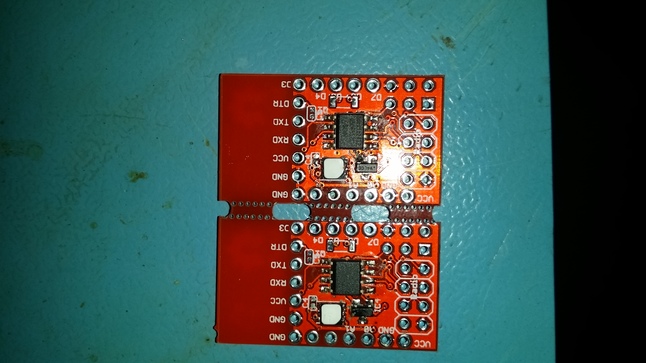
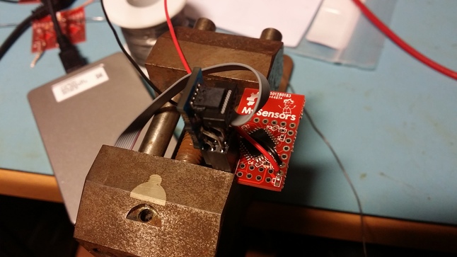
A couple of days ago I promised pictures of the new boards. Unfortunately I have been busy with some other projects :s (I hate it, when work related projects take too much of the spare time..).
Anyway, here are a couple of pictures, not the best quality, as it was a couple of quick snaps I took when I received the boards last week..
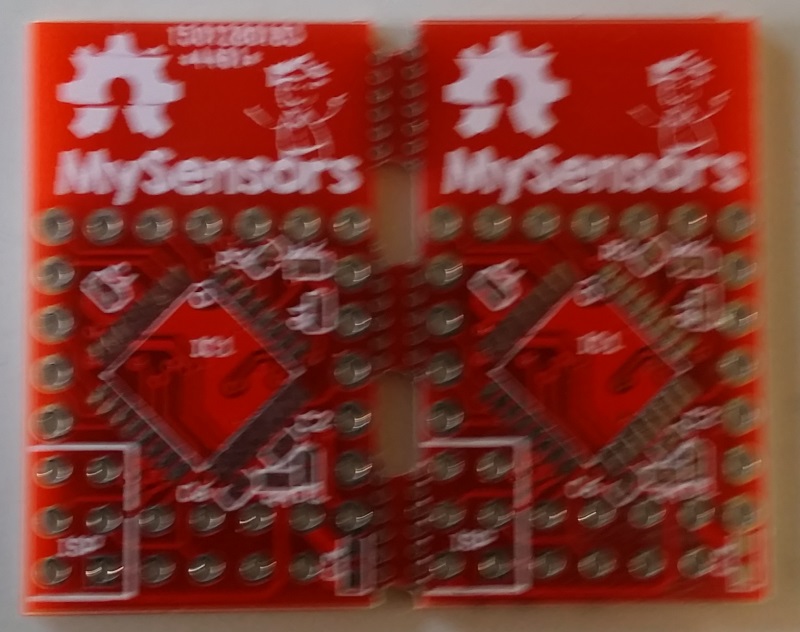
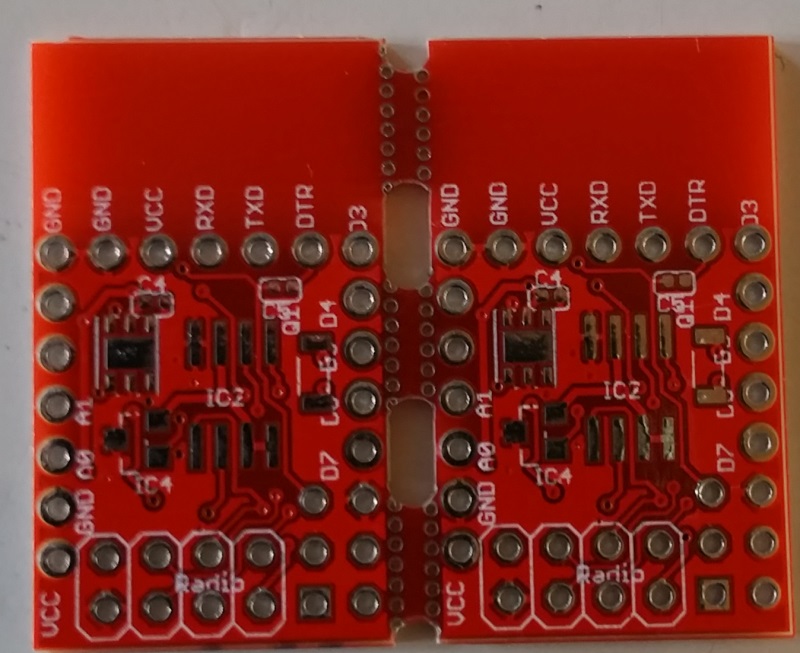
The front one is a bit blurry, sorry about that, but that is what I have at the moment..
@bjornhallberg as you can see it seems that it works quite well with adding the break tabs
-
A couple of days ago I promised pictures of the new boards. Unfortunately I have been busy with some other projects :s (I hate it, when work related projects take too much of the spare time..).
Anyway, here are a couple of pictures, not the best quality, as it was a couple of quick snaps I took when I received the boards last week..
The front one is a bit blurry, sorry about that, but that is what I have at the moment..
@bjornhallberg as you can see it seems that it works quite well with adding the break tabs
@tbowmo Looks great! I hope my regulators turn out as nice. They should hopefully arrive next week.
Best thing about the panelizer is obviously if you mass produce different sized boards, and use 10x10 cm PCBs (that are almost half the price / square cm), not only fitting a ton of boards in one space, but beating the freeware limitation in Eagle.
-
So almost finished the first two boards of the new revision..
I changed the footprint of all the SMD capacitors, and resistors, to footprints recomended by the manufacturer we are in dialog with for the mass production. Only problem is, that it's a nightmare soldering the 0402 smd components now, because the footprints are much smaller than what was used on the first revision.
Anyway, only missing decoupling capacitors now, so I'm going to power it up, just to see if everything works like it should.
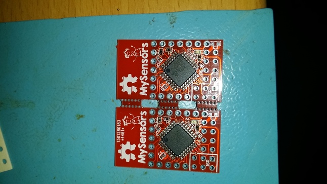
The two first is also with atsha204 mounted! Hope that everything is connected as it should be :)
First powerup seems to be ok. no excessive power ussage, and bootloader is successfully dumped into the first board. So it seems like a success sofar. (Even LED lights up during bootloader startup.. So that's also a success :))
Also ATSHA204 is confirmed working on the first prototype!
-
Properly done!
-
so @tbowmo when can we order em ? just waiting to get a may be around 10 to start with :)
-
To my best knowledge at the moment, it will be Q2 this year.
It should work, as the extra components added in rev. 2, have been verified as working (it's the atsha204 chip, for signing purposes). Everything else should be working, as I haven't altered in the schematics, so connections should be the same as the previous version.