Minimal design thoughts
-
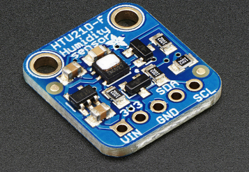
The board has humidity/temperature build in. So we only need space for maybe one extra sensor (question is how large volume this would need?).
Punch out holes for wires to external things like permanent power, buttons or reed-switches.Click on cover would be nice but requires more accuracy in the making. A screw wouldn't be a big problem.
Many variables... ;)
@hek I know , yes for the T/H sensor. As we put 2 AA battery, we have to know if we want to stack sensor/battery or not...otherwise, battery and sensor will be on the same plan.
I think that we can start without extra sensor, and add it in function of request, I'm going to buy a 3D printer, It will be my first tests. -
-
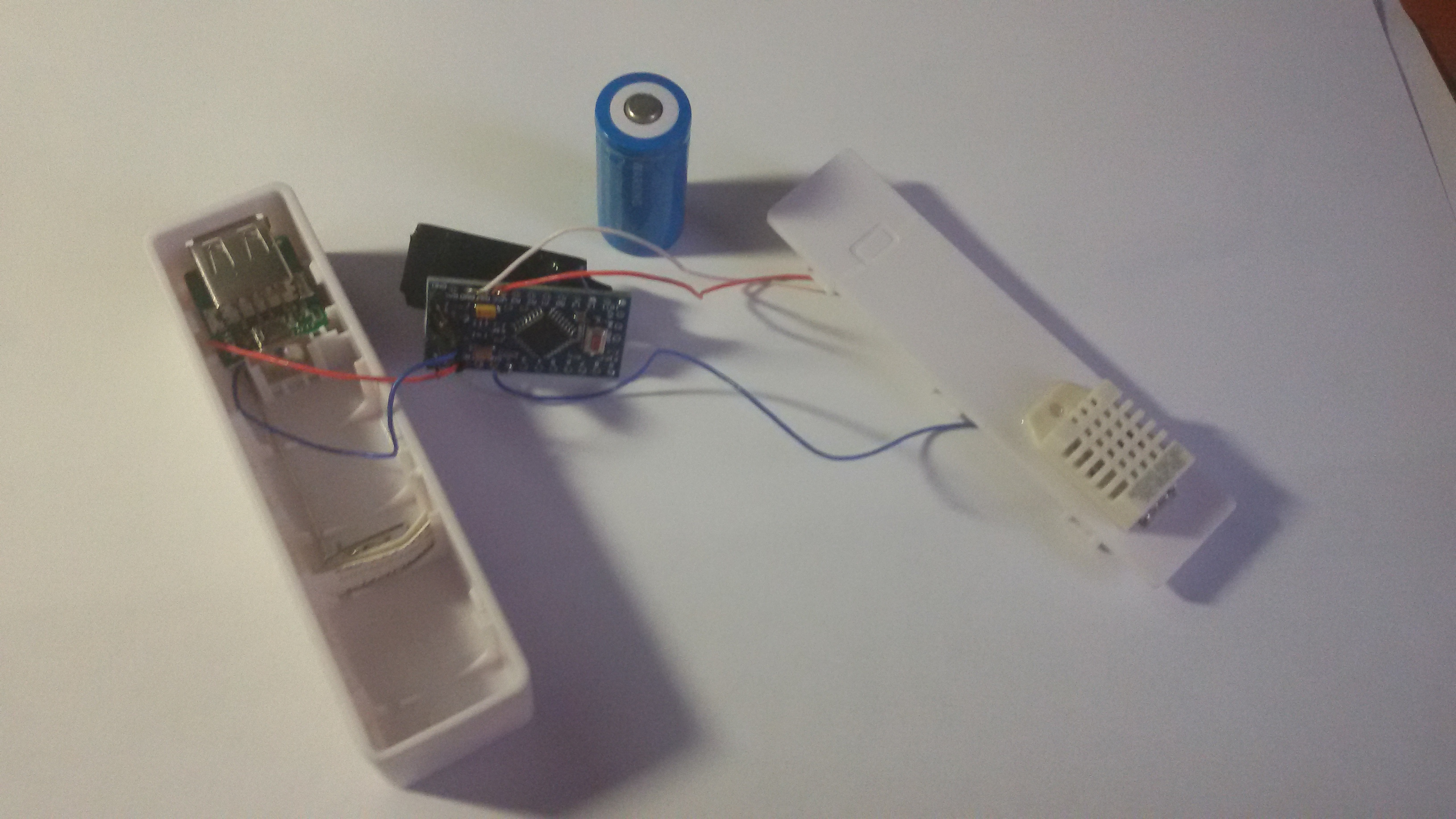
Why do not use CR123A accumulator?
It is smaller and can be charged.
And not nide regulatorI use box with charger. With CR123A accumulator.
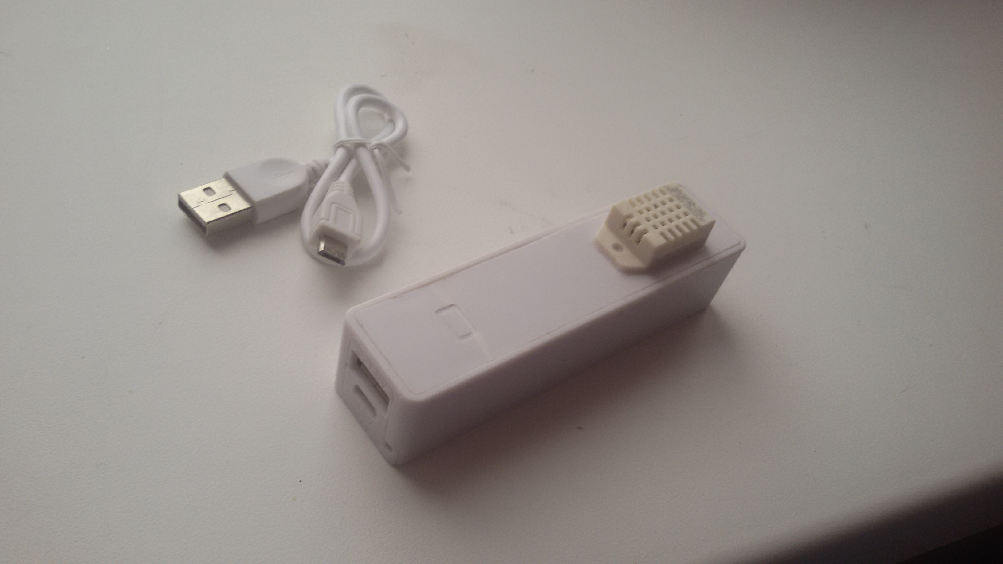
http://www.ebay.com/itm/2600Mah-USB-Portable-External-Battery-Charger-Power-Bank-for-Cell-Mobile-Phone-/301514424642?pt=LH_DefaultDomain_0&var=&hash=item4633a90142Very cheap
-
Why do not use CR123A accumulator?
It is smaller and can be charged.
And not nide regulatorI use box with charger. With CR123A accumulator.
http://www.ebay.com/itm/2600Mah-USB-Portable-External-Battery-Charger-Power-Bank-for-Cell-Mobile-Phone-/301514424642?pt=LH_DefaultDomain_0&var=&hash=item4633a90142Very cheap
-
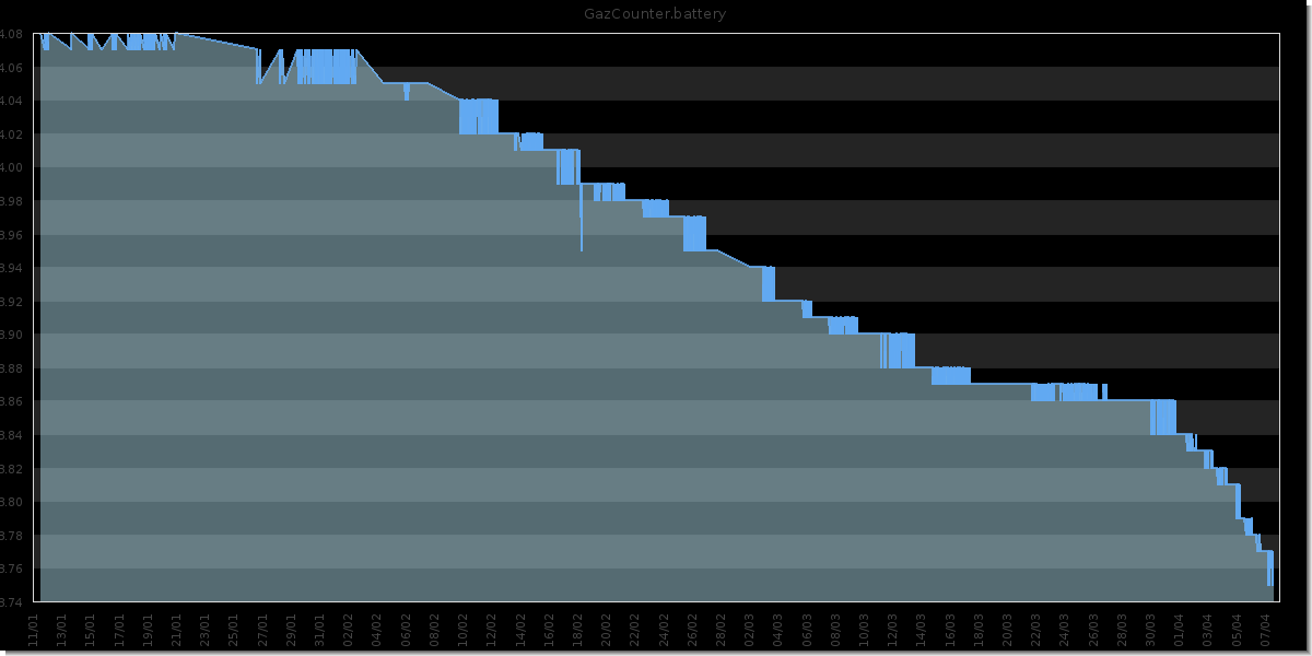
CR123A in full charge has 4.07v
Gas counter started 2014/11/01.
In winter, temperatures drop below -10
-
You say that it don't need a regulator? the battery voltage is 4.07 when fully charged, that is 0.47V above the absolute maximum rating of the NRF24L01+, as it's only rated to 3.6V maximum. Same goes for the Si7021, maximum supply voltage is 3.6V.
So CR123A is not a good battery, unless you put a regulator in the loop, which then again uses current, and causes a voltage drop from battery supply
-
DHT22 = 3.3-6V DC
CR123A = 3.6v ( Bat full charge i have 4.07v )
NRF24L01+ = 3.6
I have 8 device and his work with CR123A for 6 months
When charge some device cannot translate packets, but after work@Ivan-Z I think you are lucky... I burned a few radio's with a similar setup (with LiPO solar charger) I like your minimal design. If you replace the DHT sensor with a htu21 you can make it even smaller. There are a few htu21d boards with a 3.3v regulator on it which you could use to power the radio.
-
@AWI
What regulator do you use?I do not use the regulator because it has a extremeconsumption
AMS1117-3.3 = 5~10mV in idle@Ivan-Z I use the XC6206 series regulator. most of the times. The quiescent current for this one is very low 1-3 uA. This regulator is used by many of the sensor board suppliers to supply sensors with 3.3v Eg. In many cases (eg Adafruit) you can use the board as a "3.3v power supply"
-
Hi guys. I'm waiting for your board!
the only concern is about the 2xAA batteries adoption that could increase the overall size of a sensor node to a "normal node" size ( http://www.seeedstudio.com/depot/s/devduino.html?search_in_description=0).
I would like a stack as following: battery+board+radio. with the same footprint of the radio module.
The battery could be a CR123 with regulator, and the holder could be a pcb holder as this: http://www.memoryprotectiondevices.com/datasheets/BH-CR2-PC-datasheet.pdf
I actually ordered some of these: http://www.elecrow.com/devduino-sensor-node-v4-atmega-328-p-1201.html, at this moment the closest to my size requirements.
What do you think.? -
Hi guys. I'm waiting for your board!
the only concern is about the 2xAA batteries adoption that could increase the overall size of a sensor node to a "normal node" size ( http://www.seeedstudio.com/depot/s/devduino.html?search_in_description=0).
I would like a stack as following: battery+board+radio. with the same footprint of the radio module.
The battery could be a CR123 with regulator, and the holder could be a pcb holder as this: http://www.memoryprotectiondevices.com/datasheets/BH-CR2-PC-datasheet.pdf
I actually ordered some of these: http://www.elecrow.com/devduino-sensor-node-v4-atmega-328-p-1201.html, at this moment the closest to my size requirements.
What do you think.?@Roberto-Brunialti I am looking forward to this board also. I deployed a few Devduino V4's. These are really well built but lack the "minimal" size, have only a few connectors (enough in most cases as a good temp/hum sensor is on board).. And "restrict" you to the use of non-rechargable CR123 cells (3V,no regulator). I will love the very small footprint combined with the flexibility in power sources (and extra features) in the "Minimal design thoughts" design. :heart_eyes:
-
Think we should rename the thread to "Mysensors Micro" as this is the new name, since it's the first "official" board from mysensors.
Anyway, just got a couple of pictures from the factory in China, they have build the first batch of 5 pcb's that they are verifying at the moment, and then they should be shipped to us (either @hek or me?) and then we need to verify it, before giving a go on the production.
So we are comming closer to a "launch" of the device.
Yep, might also be good to create a new thread in Announcement when it has been launched (and is for sale) with a back-reference here for history/design decisions made by you.
I should probably start working on a more complete page on the main site with more details and illustrations.
-
In your design, C3, the nrf 4u7 capacitor, is a classic ceramic capacitor. In the mysensors tutorial, they write a polarized capacitor is better for the NRF. I use tantalum capacitor wich are bigger but is there a difference with the ceramic one for the nrf. I would like to use a ceramic 0603 too if there is no difference for nrf.
Thank's
-
will it be possible to use this board pcb without soldering the sensor , flash and security chip?