rs485 on nano
-
@wimd include debug and remove inclusion from the sketches and it should be ok. I have ordered new rs485 shield, i expect that to be the issue..
-
@wimd include debug and remove inclusion from the sketches and it should be ok. I have ordered new rs485 shield, i expect that to be the issue..
-
@skatun my problem is solve . you test this and feedback me. use 3.3v and gnd pins in arduino use for rs485 module.
-
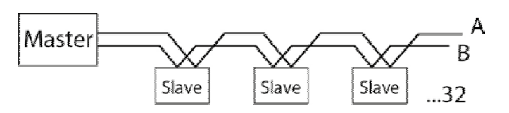
@Reza Though your two pictures are both bus topologies, your first one is a star bus topology and your second is a linear bus topology. As to your second question "so in end of A and B , what am i do ?" Depending on a few factors such as equipment connected, cable type, cable length and data speed (baud rate) used, you may or may not need a termination resistor at the end of the line. For short runs you typically won't need them, but if you have hundreds of feet you are working with, you may want them, especially if you want to run at a higher baud like 115200 or higher. As to the resistor value, just do a google search for "RS485 termination resistor."
-
This is how you build your network.
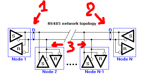
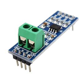
I assume that you use these :
Node 1 is the MAX485 RS-485 Module connected to your gateway.
Node N is the MAX485 RS-485 Module connected to your last sensor of your network.Between node 1 and N you can add addtional nodes but you need to keep the bus structure.
Important are the terminating resistors (1) and (2). They are R7 on the RS-485 module.
If you add modules between node 1 and node N and you have a failure in transmitting, check then with removal of R7 on that added node. -
This is how you build your network.
I assume that you use these :
Node 1 is the MAX485 RS-485 Module connected to your gateway.
Node N is the MAX485 RS-485 Module connected to your last sensor of your network.Between node 1 and N you can add addtional nodes but you need to keep the bus structure.
Important are the terminating resistors (1) and (2). They are R7 on the RS-485 module.
If you add modules between node 1 and node N and you have a failure in transmitting, check then with removal of R7 on that added node.@wimd
i use this module (rs485) . for max 30 or 40 meter. is need resistors ? ( if need 100 ohm is good ?)
i think the problem that @skatun told was solve with 3.3v pin on arduino but no. i use static ID for nodes and remove INCLUSION MODE in gateway but when connect i have error:2035 !TSM:FPAR:NO REPLY 2037 TSM:FPAR 2055 TSF:MSG:SEND,1-1-255-255,s=255,c=3,t=7,pt=0,l=0,sg=0,ft=0,st=OK: 4063 !TSM:FPAR:NO REPLY 4065 TSM:FPAR 4082 TSF:MSG:SEND,1-1-255-255,s=255,c=3,t=7,pt=0,l=0,sg=0,ft=0,st=OK: 6090 !TSM:FPAR:NO REPLY 6092 TSM:FPAR 6110 TSF:MSG:SEND,1-1-255-255,s=255,c=3,t=7,pt=0,l=0,sg=0,ft=0,st=OK: 8118 !TSM:FPAR:FAIL 8119 TSM:FAIL:CNT=1 8121 TSM:FAIL:PDTafter some reset and change pins of vcc and gnd , when use 3.3v in gateway for vcc rs485 module i see (in serial monitor) node is connect to gateway. so i think this is ok always. but today i try for new node and i see same problem again
do you think this is related to power ? -
i found a thing about this . i think all of problem is related to power ! when power of node is with a adaptor 1A and power of gateway is with usb of raspberry so i have this error "!TSM:FPAR:NO REPLY" but when connect both ( node and gateway to laptop with usb) after several test i see all of connect is ok ( several reset and connect/disconnect usb cable) . i am beginner sorry , so for this what am i do ? can i use another power for vcc and gnd rs485 module ? how ? or you have better solution ?
-
i tested again . connected gateway to my laptop (use domoticz for laptop) and use a 30 meter wire between gateway and first node. and again use a 5 meter wire for second node ( without any resistor). when start domoticz , nodes detect easy and start working well. i test again and again (with reset and power off/on)but this is ok and dont any problem(relay give command and send ack and all of thing is true) . then i connect gateway to raspberry (2 nodes is connect to laptop yet) so for a short time relay worked ( 2 - 3 command send and relay on without ack ) then all command can not send....
again i connect gateway to laptop and all command send and ok .
so i think this is related to power of usb port (raspberry)
can i use rx-tx gpio on raspberry and arduino and use other power for arduino ?how configure on raspberry ? thank you -
Many hours I solved why MySe485 example does not work :angry: ... I tried Mega, Uno, Mini, Nano, reinstallation of IDE, libraries, ClearEepromConfig, HWserial / AltSoftSerial / direct (Tx <> Rx) + (Rx <> TX) without MAX485 ...
The other day I came across this forum and the solution is:
#define MY_NODE_ID xx
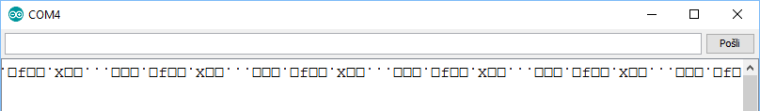
I saw a bug that RS485 communication is bad, because it is illegible. My mistake, the communication between GW and the node is not readable ASCII ...
RS485 communication: Node waiting to GW respone:
-
i tested again . connected gateway to my laptop (use domoticz for laptop) and use a 30 meter wire between gateway and first node. and again use a 5 meter wire for second node ( without any resistor). when start domoticz , nodes detect easy and start working well. i test again and again (with reset and power off/on)but this is ok and dont any problem(relay give command and send ack and all of thing is true) . then i connect gateway to raspberry (2 nodes is connect to laptop yet) so for a short time relay worked ( 2 - 3 command send and relay on without ack ) then all command can not send....
again i connect gateway to laptop and all command send and ok .
so i think this is related to power of usb port (raspberry)
can i use rx-tx gpio on raspberry and arduino and use other power for arduino ?how configure on raspberry ? thank you -
Many hours I solved why MySe485 example does not work :angry: ... I tried Mega, Uno, Mini, Nano, reinstallation of IDE, libraries, ClearEepromConfig, HWserial / AltSoftSerial / direct (Tx <> Rx) + (Rx <> TX) without MAX485 ...
The other day I came across this forum and the solution is:
#define MY_NODE_ID xx
I saw a bug that RS485 communication is bad, because it is illegible. My mistake, the communication between GW and the node is not readable ASCII ...
RS485 communication: Node waiting to GW respone:
@vikmad Are your gateway and receiving node baud rates the same? You can get gibberish like that if your baud rates differ between nodes.
Vera Plus running UI7 with MySensors, Sonoffs and 1-Wire devices
Visit my website for more Bits, Bytes and Ramblings from me: http://dan.bemowski.info/ -
@vikmad Are your gateway and receiving node baud rates the same? You can get gibberish like that if your baud rates differ between nodes.
-
@Reza
Maybe stupid question from me, but have got you connected ground wires between nodes?
Not only A and B?
http://www.chipkin.com/rs485-cables-why-you-need-3-wires-for-2-two-wire-rs485/@kimot said in rs485 on nano:
@Reza
Maybe stupid question from me, but have got you connected ground wires between nodes?
Not only A and B?no i use just 2 wire ( A & B ) . but problem is solve. i change power of raspberry. this work well !
this is compulsion (wire for ground) ? or if i connect ground of 2 nodes is better ?
-
No, connecting ground is not mandatory.. In fact, i would not recommend it at all, especialy not on longer bus lengts.. Just use A&B
If you have shielded cables.. Connect the shielding to gnd on 1 side only and leave the other side unconnected..
This will provide shielding but prevent ground loop issues.