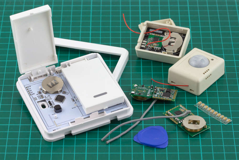
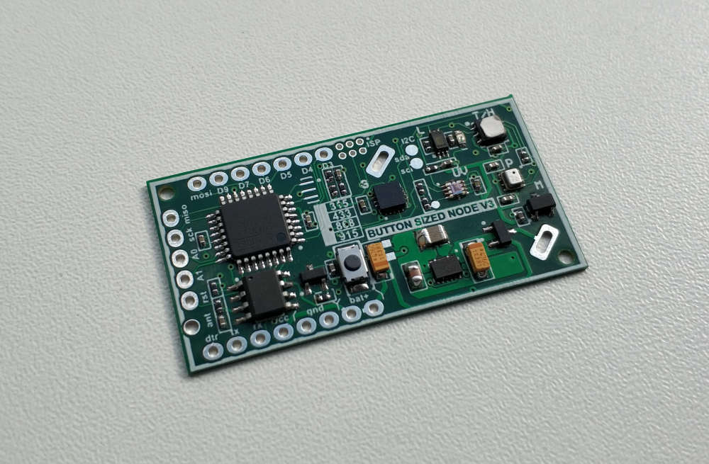
💬 Button size radionode with sensors swarm extension
-
while measuring current draw , was there FDTI adapter connected also?
@yury No I ran them on just a 2032 battery at the time, just had it in an external battery holder. I also removed the LDO on one of the boards and bridged the two top pads, with no apparent effect.
Unless there is something wrong with my DMM.
-
@yury No I ran them on just a 2032 battery at the time, just had it in an external battery holder. I also removed the LDO on one of the boards and bridged the two top pads, with no apparent effect.
Unless there is something wrong with my DMM.
@bjornhallberg I have the same v1 board you have with a sleeping power consumption being 5uA. I also have Si1132 sensor soldered and had some issues with power consumption initially as the standard Si1132 lib did not implement sleep function for this sensor.
- what sensors do you have? Do they properly put to sleep? BH1760?
- can you share the sketch?
- removing the LDO will not help you to bring down consumption from 3mA. 3mA most likely mean your radio is not sleeping. Such consumption will kill CR2032 very quickly - no chance running the board on such consumption
- did you try a different multimeter?
- there could be a problem with one of the tantalum capacitor. @yury could you remind which one has to be removed please?
I suggest you start with 5)
-
@bjornhallberg I have the same v1 board you have with a sleeping power consumption being 5uA. I also have Si1132 sensor soldered and had some issues with power consumption initially as the standard Si1132 lib did not implement sleep function for this sensor.
- what sensors do you have? Do they properly put to sleep? BH1760?
- can you share the sketch?
- removing the LDO will not help you to bring down consumption from 3mA. 3mA most likely mean your radio is not sleeping. Such consumption will kill CR2032 very quickly - no chance running the board on such consumption
- did you try a different multimeter?
- there could be a problem with one of the tantalum capacitor. @yury could you remind which one has to be removed please?
I suggest you start with 5)
@alexsh1 Thanks for the suggestions! Reassuring to know that you succeeded.
- I haven't added any sensors so it's just the default ones.
- https://github.com/EasySensors/ButtonSizeNode ... may need some cleaning up @Koresh or do we use v2 code for v1 sensor as well?
- I thought as much ... damn. I'm using the CW version radio with the adapter plate. I also thought about the radio but unlike the NRF radio this one should work with no counterfeit units?
No my other DMM was out of batteries.Found my old crappy DMM and it says the same, ~2mA.- I did remove both caps and it's still at ~2mA.
You're probably right about something not sleeping. Or else I've done a horrible soldering job on the four radios I've attached so far. All four sensors behave pretty much the same.
Also, at least on Domoticz they changed things around now so you have to use V_LEVEL instead of V_LIGHT_LEVEL or what? https://www.domoticz.com/forum/viewtopic.php?t=18577 With V_LIGHT_LEVEL I get some incomprehensible percent value reported.
-
No - please double check the board. There are options for a few sensors. Which ones do you have. Sensors on board.
-
Code really depends on sensors on board you have.
-
This is not about counterfeit radio. Just radio NOT SLEEPING. That's it.
-
OK.
-
OK
First thing first. Let's deal with your sleeping problem.
Identify which sensors you have on board or post a good quality photo of the board.
Try to use minimum sketch (see commends below - choose the correct Mhz band):
and measure the current#define MY_DEBUG #define MY_RADIO_RFM69 // Please use one!!!!!! //#define MY_RFM69_FREQUENCY RF69_433MHZ //#define MY_RFM69_FREQUENCY RF69_868MHZ //#define MY_RFM69_FREQUENCY RF69_915MHZ #define MY_NODE_ID AUTO #define MY_TRANSPORT_UPLINK_CHECK_DISABLED #define MY_PARENT_NODE_IS_STATIC #define MY_PARENT_NODE_ID 0 #include <Wire.h> #include <BH1750.h> //Make sure you are using this one https://github.com/claws/BH1750 BH1750 lightMeter; #include "SparkFun_Si7021_Breakout_Library.h" Weather sensor; #include <MySensors.h> #define SPIFLASH_BLOCKERASE_32K 0xD8 #define SPIFLASH_CHIPERASE 0x60 void setup() { lightMeter.begin(BH1750::ONE_TIME_LOW_RES_MODE); noInterrupts(); _flash.initialize(); _flash.sleep(); interrupts(); } void loop() { lightMeter.begin(BH1750::ONE_TIME_LOW_RES_MODE); lux = lightMeter.readLightLevel(); Serial.print("Lux="); Serial.println(lux); sleep(10000); } -
@alexsh1 I may have made a bit of a mistake with some glitchy chinese test probes. De-glitched cables and connected to a proper lab power supply gave very different readings (with the default git-sketch) ...
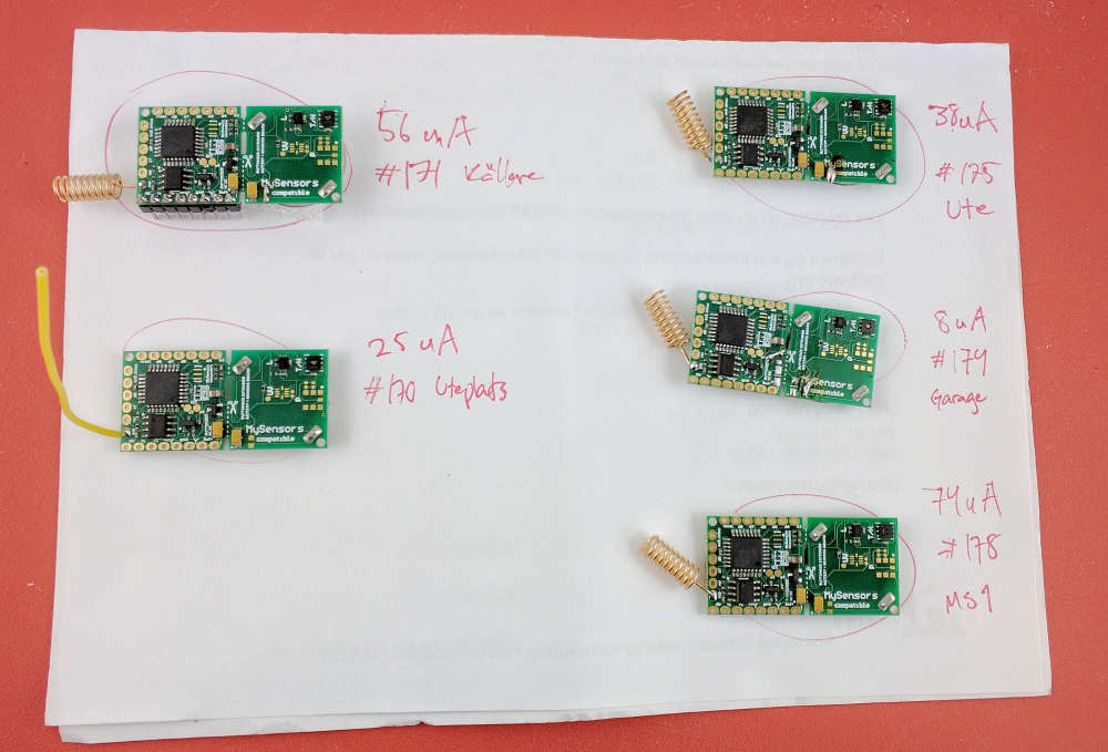
Still a bit confused over the differing readings. I get that the board I stripped from regulator and capacitors would perform better though. So do I have to do the same for all the other boards as well? Of course, I could save the worst performing boards for later and run them on 2xAA or something in places where space isn't an issue.
-
@alexsh1 I may have made a bit of a mistake with some glitchy chinese test probes. De-glitched cables and connected to a proper lab power supply gave very different readings (with the default git-sketch) ...
Still a bit confused over the differing readings. I get that the board I stripped from regulator and capacitors would perform better though. So do I have to do the same for all the other boards as well? Of course, I could save the worst performing boards for later and run them on 2xAA or something in places where space isn't an issue.
Hi @bjornhallberg.
I've done many tests today with your code. All tested boards were the newer ones. So I completely had no ideas until I read your last message. Now all is clear for me. You have battery draining ~10-100ua, not 1-2mA. As I see your boards contain 107J capacitors. It was an absolutely failed batch of capacitors. We resoldered all of these capacitors on all the boards after we had found this problem with @alexsh1. Unfortunatelly some of these boards had been sent until we found this problem. We are so sorry you had to deal with these failed boards. I suggest I send you some new tested buttonsized v1 boards to you. Also I can send good capacitors to rework failed boards and some of my new interesting boards for free. -
@alexsh1 I may have made a bit of a mistake with some glitchy chinese test probes. De-glitched cables and connected to a proper lab power supply gave very different readings (with the default git-sketch) ...
Still a bit confused over the differing readings. I get that the board I stripped from regulator and capacitors would perform better though. So do I have to do the same for all the other boards as well? Of course, I could save the worst performing boards for later and run them on 2xAA or something in places where space isn't an issue.
@bjornhallberg @Koresh That's what I wrote a few posts above - start with the capacitors :-)
My suggestion - get a decent DMM. Brymen BM235 or 121GW or any Fluke.
Measuring a sleeping current is challenging and some unexpansive Chinese DMM manage it just really well. BUT! You do not want to waist your time just because your meter is crap and was completely off on some readings. -
Hi @bjornhallberg.
I've done many tests today with your code. All tested boards were the newer ones. So I completely had no ideas until I read your last message. Now all is clear for me. You have battery draining ~10-100ua, not 1-2mA. As I see your boards contain 107J capacitors. It was an absolutely failed batch of capacitors. We resoldered all of these capacitors on all the boards after we had found this problem with @alexsh1. Unfortunatelly some of these boards had been sent until we found this problem. We are so sorry you had to deal with these failed boards. I suggest I send you some new tested buttonsized v1 boards to you. Also I can send good capacitors to rework failed boards and some of my new interesting boards for free.@koresh Package went under the "Postnord" radar! Woohoo, perfect! I will start replacing the old capacitors and finally be able to deploy the sensors. Very nice of you to include some product samples as well. Really excited about these sensors!
-
Hi guys, quick question: I'm using a LiFePo4 3.2V battery directly on the board (sensors part removed).
Somehow the battery percentage always shows 100 - how should I change the default code to make this work?Right now I'm using the code like here: https://github.com/EasySensors/ButtonSizeNode/blob/master/ButtonSizeNode.ino
@christoph-blank Hi, thanks for using this board. In the first version of this board the divider is conected after LDO, so you can't measure voltage above 3.3V. In the second version the divider is connected to the battery directly. You use 3.2v battery so it is not problem for you. But LiFePo4 battery has very flat discharge curve so it can be hard to read this level with reasonable accuracy.

I will try to find LiFePo4 battery and add some piece of code soon. Yet you can play with followed code// Get the battery Voltage int sensorValue = analogRead(BATTERY_SENSE_PIN); // 1M, 470K divider across battery and using internal ADC ref of 1.1V1 // ((1e6+470e3)/470e3)*1.1 = Vmax = 3.44 Volts /* The MySensors Lib uses internal ADC ref of 1.1V which means analogRead of the pin connected to 470kOhms Battery Devider reaches * 1023 when voltage on the divider is around 3.44 Volts. 2.5 volts is equal to 750. 2 volts is equal to 600. * RFM 69 CW works stable up to 2 volts. Assume 2.5 V is 0% and 1023 is 100% battery charge * RFM 69 HCW works stable up to 2.5 volts (sometimes it can work up to 2.0V). Assume 2.5 V is 0% and 1023 is 100% battery charge * 3.3V ~ 1023 * 3.0V ~ 900 * 2.5V ~ 750 * 2.0V ~ 600 */ #ifdef MY_IS_RFM69HW int batteryPcnt = (sensorValue - 750) / 1.5; #else int batteryPcnt = (sensorValue - 600) / 3; #endif -
@christoph-blank Hi, thanks for using this board. In the first version of this board the divider is conected after LDO, so you can't measure voltage above 3.3V. In the second version the divider is connected to the battery directly. You use 3.2v battery so it is not problem for you. But LiFePo4 battery has very flat discharge curve so it can be hard to read this level with reasonable accuracy.
I will try to find LiFePo4 battery and add some piece of code soon. Yet you can play with followed code// Get the battery Voltage int sensorValue = analogRead(BATTERY_SENSE_PIN); // 1M, 470K divider across battery and using internal ADC ref of 1.1V1 // ((1e6+470e3)/470e3)*1.1 = Vmax = 3.44 Volts /* The MySensors Lib uses internal ADC ref of 1.1V which means analogRead of the pin connected to 470kOhms Battery Devider reaches * 1023 when voltage on the divider is around 3.44 Volts. 2.5 volts is equal to 750. 2 volts is equal to 600. * RFM 69 CW works stable up to 2 volts. Assume 2.5 V is 0% and 1023 is 100% battery charge * RFM 69 HCW works stable up to 2.5 volts (sometimes it can work up to 2.0V). Assume 2.5 V is 0% and 1023 is 100% battery charge * 3.3V ~ 1023 * 3.0V ~ 900 * 2.5V ~ 750 * 2.0V ~ 600 */ #ifdef MY_IS_RFM69HW int batteryPcnt = (sensorValue - 750) / 1.5; #else int batteryPcnt = (sensorValue - 600) / 3; #endif@koresh said in 💬 Button size radionode with sensors swarm extension:
@christoph-blank Hi, thanks for using this board. In the first version of this board the divider is conected after LDO, so you can't measure voltage above 3.3V. In the second version the divider is connected to the battery directly. You use 3.2v battery so it is not problem for you. But LiFePo4 battery has very flat discharge curve so it can be hard to read this level with reasonable accuracy.
I will try to find LiFePo4 battery and add some piece of code soon. Yet you can play with followed code// Get the battery Voltage int sensorValue = analogRead(BATTERY_SENSE_PIN); // 1M, 470K divider across battery and using internal ADC ref of 1.1V1 // ((1e6+470e3)/470e3)*1.1 = Vmax = 3.44 Volts /* The MySensors Lib uses internal ADC ref of 1.1V which means analogRead of the pin connected to 470kOhms Battery Devider reaches * 1023 when voltage on the divider is around 3.44 Volts. 2.5 volts is equal to 750. 2 volts is equal to 600. * RFM 69 CW works stable up to 2 volts. Assume 2.5 V is 0% and 1023 is 100% battery charge * RFM 69 HCW works stable up to 2.5 volts (sometimes it can work up to 2.0V). Assume 2.5 V is 0% and 1023 is 100% battery charge * 3.3V ~ 1023 * 3.0V ~ 900 * 2.5V ~ 750 * 2.0V ~ 600 */ #ifdef MY_IS_RFM69HW int batteryPcnt = (sensorValue - 750) / 1.5; #else int batteryPcnt = (sensorValue - 600) / 3; #endifThank you very much, what are the other differences between V1 and V2? I believe I have V1 but I'm not sure.
The above code is what I currently use, and I removed the sensor part of the module. However, it shows 100% until the end (until it's not sending anymore).Looking forward to your tests!
Christoph -
Hope will test the new version of this universal board soon. Now it has additional inexpensive accelerometer, magnetic sensor, led, reset button, multifootprint for lora/hw/cw radio without adapter and improoved 4layers design :)
-
hi, this looks great -- is the assembled board, or just the board itself available anywhere? newbie here, i don't know what to do. if i can buy the assembled board, it would be so fantastic. thanks!!!
-
hi, this looks great -- is the assembled board, or just the board itself available anywhere? newbie here, i don't know what to do. if i can buy the assembled board, it would be so fantastic. thanks!!!