Mysensors Gateway on OrangePi (Zero) (opi)
-
If you used this wiring scheme:
nRF24L01 | Orange Pi
_________|________________
VCC      | VCC3V3-EXT
GND      | GND
CSN      | SPI0_CS0 (SPI-CE0)
CE       | PA7 (IO-7)
MOSI     | SPI0_MOSI (SPI-MOSI)
SCK      | SPI0_CLK (SPI-CLK)
MISO     | SPI0_MISO (SPI-MISO)
Then you should initialize the radio with:
RF24 radio(7,0);Worked for me:
root@opi-pc-1:~/RF24-master/examples_linux# ./gettingstarted RF24/examples/GettingStarted/ STATUS = 0x0e RX_DR=0 TX_DS=0 MAX_RT=0 RX_P_NO=7 TX_FULL=0 RX_ADDR_P0-1 = 0x65646f4e32 0x65646f4e31 RX_ADDR_P2-5 = 0xc3 0xc4 0xc5 0xc6 TX_ADDR = 0x65646f4e32 RX_PW_P0-6 = 0x20 0x20 0x00 0x00 0x00 0x00 EN_AA = 0x3f EN_RXADDR = 0x02 RF_CH = 0x4c RF_SETUP = 0x07 CONFIG = 0x0e DYNPD/FEATURE = 0x00 0x00 Data Rate = 1MBPS Model = nRF24L01+ CRC Length = 16 bits PA Power = PA_MAX ************ Role Setup *********** Choose a role: Enter 0 for pong_back, 1 for ping_out (CTRL+C to exit)Hmmm.... checked the docs again and guess what. the 26 pin header on the OPI Zero has SPI1.... instead of SPI0
Expansion Port
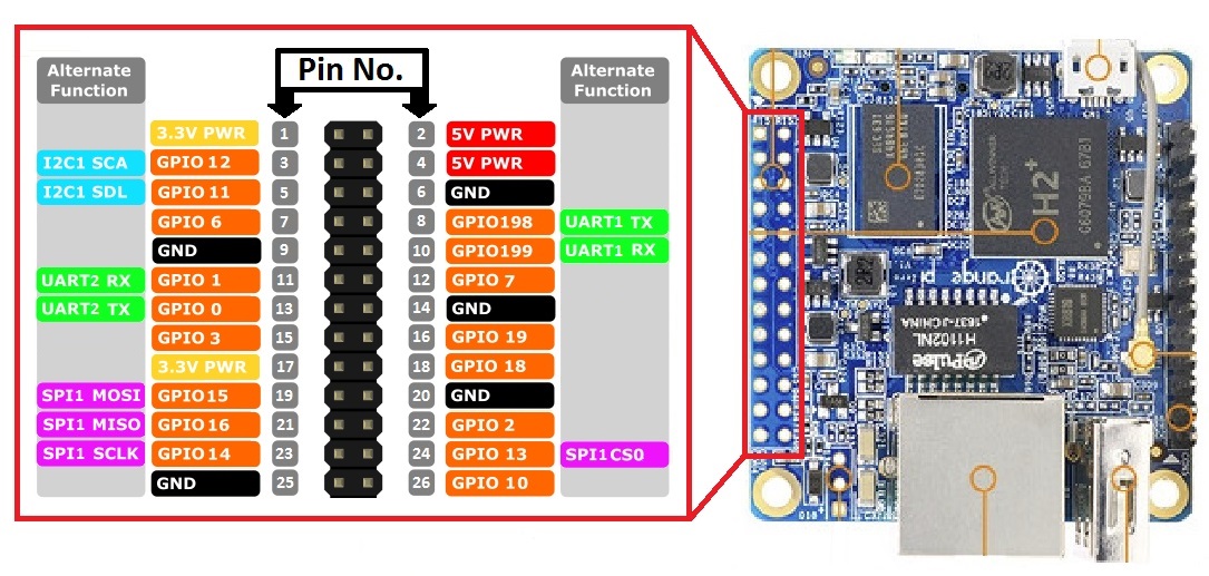
The Orange Pi Zero has a 26-pin, 0.1" unpopulated connector with several low-speed interfaces.
2x13 Header
1	3.3V	           2	5V
3	TWI0_SDA / PA12	   4	5V
5	TWI0_SCK / PA11	   6	GND
7	PWM1 / PA06	       8	UART1_TX / PG06
9	GND	               10	UART1_RX / PG07
11	UART2_RX / PA01	   12	SIM_CLK/PA_EINT7 / PA07
13	UART2_TX / PA00	   14	GND
15	UART2_CTS / PA03   16	TWI1-SDA / PA19
17	3.3V	           18	TWI1-SCK / PA18
19	SPI1_MOSI / PA15   20	GND
21	SPI1_MISO / PA16   22	UART2_RTS / PA02
23	SPI1_CLK / PA14    24	SPI1_CS / PA13
25	GND	               26	SIM_DET/PA_EINT10 / PA10
From http://linux-sunxi.org/Xunlong_Orange_Pi_Zero
If i look at /dev I only see spi0, which is most probably used for the onboard flash...root@orangepizero:/# ll /dev | grep -i spi crw------- 1 root root 153, 0 Jan 8 11:12 spidev0.0So now i need to figure out a way to get SPI1 up and running
-
@mihai.aldea Could you try the repo I'm working on (https://github.com/marceloaqno/MySensors/tree/spidev marceloaqno-spidev) adding your settings to the examples_linux/mysgw.cpp?
#define MY_RF24_CE_PIN 7 #define MY_RF24_CS_PIN 0@marceloaqno Here's the output:
./MySensors.h:258:2: error: #error No support for nRF24 radio on this platform #error No support for nRF24 radio on this platform ^ In file included from ./drivers/RF24/RF24.cpp:23:0, from ./MySensors.h:294, from examples_linux/mysgw.cpp:77: ./drivers/RF24/RF24.h:52:17: fatal error: SPI.h: No such file or directory #include <SPI.h> ^ compilation terminated. Makefile:98: recipe for target 'build/examples_linux/mysgw.o' failed make: *** [build/examples_linux/mysgw.o] Error 1 -
@Tag Use this info:
http://linux-sunxi.org/Sunxi-tools
To export /boot/script.bin, edit the output file and enable SPI1, then compile it back and reboot your OPi with the SPI1 active.If you haven't done this before, it's quite simple.
apt-get install sunxi-tools
cd ~
bin2fex /boot/script.bin > script.fex
Edit the script.fex file, find the [spi1] section and change spi_used = 0 to spi_used = 1. Save the file and exit.
Thenfex2bin script.fex > /boot/script.binReboot, then you should have the SPI1 active.
-
@marceloaqno
i have error yet
orangepi is a good board. please work at this board and run mysensors gateway on this, i follow this topic when you can fix this on orange pi . thank you -
@Tag Use this info:
http://linux-sunxi.org/Sunxi-tools
To export /boot/script.bin, edit the output file and enable SPI1, then compile it back and reboot your OPi with the SPI1 active.If you haven't done this before, it's quite simple.
apt-get install sunxi-tools
cd ~
bin2fex /boot/script.bin > script.fex
Edit the script.fex file, find the [spi1] section and change spi_used = 0 to spi_used = 1. Save the file and exit.
Thenfex2bin script.fex > /boot/script.binReboot, then you should have the SPI1 active.
Yep already found it :) problem was the old version of the tools, it was not able to decompile the script.bin file...
[update]
- modified the script file,
- changed spi_used = 1
- compiled back and rebooted
just 1 device file in called spidev0.0 no new device files are created..... :(
dmesg output:
[    0.814287] sunxi_spi_chan_cfg()1376 - [spi-0] has no spi_regulator.
[    0.814316] sunxi_spi_chan_cfg()1376 - [spi-1] has no spi_regulator.
[    0.815569] spi spi0: master is unqueued, this is deprecated
[    0.816776] spi spi1: master is unqueued, this is deprecated
Thx, will keep you posted!
-
@marceloaqno
i have error yet
orangepi is a good board. please work at this board and run mysensors gateway on this, i follow this topic when you can fix this on orange pi . thank you@Reza Was /sys/class/gpio/export created after modprobe gpio-sunxi?
@mihai-aldea Could you send the complete make and configure output so I can check if your system is correctly detected?
-
@Reza Was /sys/class/gpio/export created after modprobe gpio-sunxi?
@mihai-aldea Could you send the complete make and configure output so I can check if your system is correctly detected?
@marceloaqno said:
@mihai-aldea Could you send the complete make and configure output so I can check if your system is correctly detected?
Here it is
root@opi-pc-1:~/rf24opi/MySensors# ./configure --soc=H3 [OK] init system detected: systemd [SECTION] Saving configuration. [SECTION] Cleaning previous builds. [OK] Finished. root@opi-pc-1:~/rf24opi/MySensors# make gcc -MT build/drivers/Linux/log.o -MMD -MP -march=armv8-a -mtune=cortex-a53 -mfpu=neon-vfpv4 -mfloat-abi=hard -DMY_RADIO_NRF24 -DMY_GATEWAY_LINUX -DMY_DEBUG -Ofast -g -Wall -Wextra -I. -I./core -I./drivers/Linux -c drivers/Linux/log.c -o build/drivers/Linux/log.o g++ -MT build/drivers/Linux/IPAddress.o -MMD -MP -march=armv8-a -mtune=cortex-a53 -mfpu=neon-vfpv4 -mfloat-abi=hard -DMY_RADIO_NRF24 -DMY_GATEWAY_LINUX -DMY_DEBUG -Ofast -g -Wall -Wextra -I. -I./core -I./drivers/Linux -c drivers/Linux/IPAddress.cpp -o build/drivers/Linux/IPAddress.o g++ -MT build/drivers/Linux/noniso.o -MMD -MP -march=armv8-a -mtune=cortex-a53 -mfpu=neon-vfpv4 -mfloat-abi=hard -DMY_RADIO_NRF24 -DMY_GATEWAY_LINUX -DMY_DEBUG -Ofast -g -Wall -Wextra -I. -I./core -I./drivers/Linux -c drivers/Linux/noniso.cpp -o build/drivers/Linux/noniso.o g++ -MT build/drivers/Linux/Print.o -MMD -MP -march=armv8-a -mtune=cortex-a53 -mfpu=neon-vfpv4 -mfloat-abi=hard -DMY_RADIO_NRF24 -DMY_GATEWAY_LINUX -DMY_DEBUG -Ofast -g -Wall -Wextra -I. -I./core -I./drivers/Linux -c drivers/Linux/Print.cpp -o build/drivers/Linux/Print.o g++ -MT build/drivers/Linux/EthernetClient.o -MMD -MP -march=armv8-a -mtune=cortex-a53 -mfpu=neon-vfpv4 -mfloat-abi=hard -DMY_RADIO_NRF24 -DMY_GATEWAY_LINUX -DMY_DEBUG -Ofast -g -Wall -Wextra -I. -I./core -I./drivers/Linux -c drivers/Linux/EthernetClient.cpp -o build/drivers/Linux/EthernetClient.o g++ -MT build/drivers/Linux/compatibility.o -MMD -MP -march=armv8-a -mtune=cortex-a53 -mfpu=neon-vfpv4 -mfloat-abi=hard -DMY_RADIO_NRF24 -DMY_GATEWAY_LINUX -DMY_DEBUG -Ofast -g -Wall -Wextra -I. -I./core -I./drivers/Linux -c drivers/Linux/compatibility.cpp -o build/drivers/Linux/compatibility.o g++ -MT build/drivers/Linux/SerialPort.o -MMD -MP -march=armv8-a -mtune=cortex-a53 -mfpu=neon-vfpv4 -mfloat-abi=hard -DMY_RADIO_NRF24 -DMY_GATEWAY_LINUX -DMY_DEBUG -Ofast -g -Wall -Wextra -I. -I./core -I./drivers/Linux -c drivers/Linux/SerialPort.cpp -o build/drivers/Linux/SerialPort.o g++ -MT build/drivers/Linux/Stream.o -MMD -MP -march=armv8-a -mtune=cortex-a53 -mfpu=neon-vfpv4 -mfloat-abi=hard -DMY_RADIO_NRF24 -DMY_GATEWAY_LINUX -DMY_DEBUG -Ofast -g -Wall -Wextra -I. -I./core -I./drivers/Linux -c drivers/Linux/Stream.cpp -o build/drivers/Linux/Stream.o g++ -MT build/drivers/Linux/SoftEeprom.o -MMD -MP -march=armv8-a -mtune=cortex-a53 -mfpu=neon-vfpv4 -mfloat-abi=hard -DMY_RADIO_NRF24 -DMY_GATEWAY_LINUX -DMY_DEBUG -Ofast -g -Wall -Wextra -I. -I./core -I./drivers/Linux -c drivers/Linux/SoftEeprom.cpp -o build/drivers/Linux/SoftEeprom.o g++ -MT build/drivers/Linux/EthernetServer.o -MMD -MP -march=armv8-a -mtune=cortex-a53 -mfpu=neon-vfpv4 -mfloat-abi=hard -DMY_RADIO_NRF24 -DMY_GATEWAY_LINUX -DMY_DEBUG -Ofast -g -Wall -Wextra -I. -I./core -I./drivers/Linux -c drivers/Linux/EthernetServer.cpp -o build/drivers/Linux/EthernetServer.o g++ -MT build/examples_linux/mysgw.o -MMD -MP -march=armv8-a -mtune=cortex-a53 -mfpu=neon-vfpv4 -mfloat-abi=hard -DMY_RADIO_NRF24 -DMY_GATEWAY_LINUX -DMY_DEBUG -Ofast -g -Wall -Wextra -I. -I./core -I./drivers/Linux -c examples_linux/mysgw.cpp -o build/examples_linux/mysgw.o In file included from examples_linux/mysgw.cpp:77:0: ./MySensors.h:258:2: error: #error No support for nRF24 radio on this platform #error No support for nRF24 radio on this platform ^ In file included from ./drivers/RF24/RF24.cpp:23:0, from ./MySensors.h:294, from examples_linux/mysgw.cpp:77: ./drivers/RF24/RF24.h:52:17: fatal error: SPI.h: No such file or directory #include <SPI.h> ^ compilation terminated. Makefile:98: recipe for target 'build/examples_linux/mysgw.o' failed make: *** [build/examples_linux/mysgw.o] Error 1 -
@marceloaqno said:
@mihai-aldea Could you send the complete make and configure output so I can check if your system is correctly detected?
Here it is
root@opi-pc-1:~/rf24opi/MySensors# ./configure --soc=H3 [OK] init system detected: systemd [SECTION] Saving configuration. [SECTION] Cleaning previous builds. [OK] Finished. root@opi-pc-1:~/rf24opi/MySensors# make gcc -MT build/drivers/Linux/log.o -MMD -MP -march=armv8-a -mtune=cortex-a53 -mfpu=neon-vfpv4 -mfloat-abi=hard -DMY_RADIO_NRF24 -DMY_GATEWAY_LINUX -DMY_DEBUG -Ofast -g -Wall -Wextra -I. -I./core -I./drivers/Linux -c drivers/Linux/log.c -o build/drivers/Linux/log.o g++ -MT build/drivers/Linux/IPAddress.o -MMD -MP -march=armv8-a -mtune=cortex-a53 -mfpu=neon-vfpv4 -mfloat-abi=hard -DMY_RADIO_NRF24 -DMY_GATEWAY_LINUX -DMY_DEBUG -Ofast -g -Wall -Wextra -I. -I./core -I./drivers/Linux -c drivers/Linux/IPAddress.cpp -o build/drivers/Linux/IPAddress.o g++ -MT build/drivers/Linux/noniso.o -MMD -MP -march=armv8-a -mtune=cortex-a53 -mfpu=neon-vfpv4 -mfloat-abi=hard -DMY_RADIO_NRF24 -DMY_GATEWAY_LINUX -DMY_DEBUG -Ofast -g -Wall -Wextra -I. -I./core -I./drivers/Linux -c drivers/Linux/noniso.cpp -o build/drivers/Linux/noniso.o g++ -MT build/drivers/Linux/Print.o -MMD -MP -march=armv8-a -mtune=cortex-a53 -mfpu=neon-vfpv4 -mfloat-abi=hard -DMY_RADIO_NRF24 -DMY_GATEWAY_LINUX -DMY_DEBUG -Ofast -g -Wall -Wextra -I. -I./core -I./drivers/Linux -c drivers/Linux/Print.cpp -o build/drivers/Linux/Print.o g++ -MT build/drivers/Linux/EthernetClient.o -MMD -MP -march=armv8-a -mtune=cortex-a53 -mfpu=neon-vfpv4 -mfloat-abi=hard -DMY_RADIO_NRF24 -DMY_GATEWAY_LINUX -DMY_DEBUG -Ofast -g -Wall -Wextra -I. -I./core -I./drivers/Linux -c drivers/Linux/EthernetClient.cpp -o build/drivers/Linux/EthernetClient.o g++ -MT build/drivers/Linux/compatibility.o -MMD -MP -march=armv8-a -mtune=cortex-a53 -mfpu=neon-vfpv4 -mfloat-abi=hard -DMY_RADIO_NRF24 -DMY_GATEWAY_LINUX -DMY_DEBUG -Ofast -g -Wall -Wextra -I. -I./core -I./drivers/Linux -c drivers/Linux/compatibility.cpp -o build/drivers/Linux/compatibility.o g++ -MT build/drivers/Linux/SerialPort.o -MMD -MP -march=armv8-a -mtune=cortex-a53 -mfpu=neon-vfpv4 -mfloat-abi=hard -DMY_RADIO_NRF24 -DMY_GATEWAY_LINUX -DMY_DEBUG -Ofast -g -Wall -Wextra -I. -I./core -I./drivers/Linux -c drivers/Linux/SerialPort.cpp -o build/drivers/Linux/SerialPort.o g++ -MT build/drivers/Linux/Stream.o -MMD -MP -march=armv8-a -mtune=cortex-a53 -mfpu=neon-vfpv4 -mfloat-abi=hard -DMY_RADIO_NRF24 -DMY_GATEWAY_LINUX -DMY_DEBUG -Ofast -g -Wall -Wextra -I. -I./core -I./drivers/Linux -c drivers/Linux/Stream.cpp -o build/drivers/Linux/Stream.o g++ -MT build/drivers/Linux/SoftEeprom.o -MMD -MP -march=armv8-a -mtune=cortex-a53 -mfpu=neon-vfpv4 -mfloat-abi=hard -DMY_RADIO_NRF24 -DMY_GATEWAY_LINUX -DMY_DEBUG -Ofast -g -Wall -Wextra -I. -I./core -I./drivers/Linux -c drivers/Linux/SoftEeprom.cpp -o build/drivers/Linux/SoftEeprom.o g++ -MT build/drivers/Linux/EthernetServer.o -MMD -MP -march=armv8-a -mtune=cortex-a53 -mfpu=neon-vfpv4 -mfloat-abi=hard -DMY_RADIO_NRF24 -DMY_GATEWAY_LINUX -DMY_DEBUG -Ofast -g -Wall -Wextra -I. -I./core -I./drivers/Linux -c drivers/Linux/EthernetServer.cpp -o build/drivers/Linux/EthernetServer.o g++ -MT build/examples_linux/mysgw.o -MMD -MP -march=armv8-a -mtune=cortex-a53 -mfpu=neon-vfpv4 -mfloat-abi=hard -DMY_RADIO_NRF24 -DMY_GATEWAY_LINUX -DMY_DEBUG -Ofast -g -Wall -Wextra -I. -I./core -I./drivers/Linux -c examples_linux/mysgw.cpp -o build/examples_linux/mysgw.o In file included from examples_linux/mysgw.cpp:77:0: ./MySensors.h:258:2: error: #error No support for nRF24 radio on this platform #error No support for nRF24 radio on this platform ^ In file included from ./drivers/RF24/RF24.cpp:23:0, from ./MySensors.h:294, from examples_linux/mysgw.cpp:77: ./drivers/RF24/RF24.h:52:17: fatal error: SPI.h: No such file or directory #include <SPI.h> ^ compilation terminated. Makefile:98: recipe for target 'build/examples_linux/mysgw.o' failed make: *** [build/examples_linux/mysgw.o] Error 1@mihai.aldea I think you're not in the right branch, could you start from scratch like this:
rm -rf marceloaqno-spidev git clone https://github.com/marceloaqno/MySensors marceloaqno-spidev cd marceloaqno-spidev git checkout spidev ./configure make -
@Reza Was /sys/class/gpio/export created after modprobe gpio-sunxi?
@mihai-aldea Could you send the complete make and configure output so I can check if your system is correctly detected?
@marceloaqno
i have not any folder "gpio" in class folder .
what am i do ? :(
can you create a new topic with all steps after full fix on orange pi ?
thank you. i follow this topic -
@marceloaqno You were right, I wasn't using the correct branch. Your instructions though did not work for me
root@opi-pc-1:~# git clone https://github.com/marceloaqno/MySensors/tree/spidev marceloaqno-spidev
Cloning into 'marceloaqno-spidev'...
fatal: repository 'https://github.com/marceloaqno/MySensors/tree/spidev/' not found
Anyway, I found another way:
git clone https://github.com/marceloaqno/MySensors.git marceloaqno-spidev
cd marceloaqno-spidev/
git pull origin spidev
./configure
make
This time it compiled successfuly, but when I fired up mysgw all I got was:
mysgw: Starting gateway...
mysgw: Protocol version - 2.2.0-beta
with no other output.
Just to be sure we're on the same note, what is the wiring schematic I should use? When I first started to tinker with RF24 on OPi I found at least two wiring schematics.
For reference here's the gpio readall on my OPi PC:+-----+-----+----------+------+---+-Orange Pi+---+---+------+---------+-----+--+ | BCM | wPi | Name | Mode | V | Physical | V | Mode | Name | wPi | BCM | +-----+-----+----------+------+---+----++----+---+------+----------+-----+-----+ | | | 3.3v | | | 1 || 2 | | | 5v | | | | 12 | 8 | SDA.0 | ALT5 | 0 | 3 || 4 | | | 5V | | | | 11 | 9 | SCL.0 | ALT5 | 0 | 5 || 6 | | | 0v | | | | 6 | 7 | GPIO.7 | ALT3 | 0 | 7 || 8 | 0 | ALT4 | TxD3 | 15 | 13 | | | | 0v | | | 9 || 10 | 0 | ALT4 | RxD3 | 16 | 14 | | 1 | 0 | RxD2 | ALT5 | 0 | 11 || 12 | 0 | ALT3 | GPIO.1 | 1 | 110 | | 0 | 2 | TxD2 | ALT5 | 1 | 13 || 14 | | | 0v | | | | 3 | 3 | CTS2 | ALT5 | 0 | 15 || 16 | 0 | ALT3 | GPIO.4 | 4 | 68 | | | | 3.3v | | | 17 || 18 | 0 | ALT3 | GPIO.5 | 5 | 71 | | 64 | 12 | MOSI | ALT4 | 0 | 19 || 20 | | | 0v | | | | 65 | 13 | MISO | ALT4 | 0 | 21 || 22 | 0 | ALT5 | RTS2 | 6 | 2 | | 66 | 14 | SCLK | ALT4 | 0 | 23 || 24 | 0 | ALT4 | CE0 | 10 | 67 | | | | 0v | | | 25 || 26 | 0 | ALT3 | GPIO.11 | 11 | 21 | | 19 | 30 | SDA.1 | ALT4 | 0 | 27 || 28 | 0 | ALT4 | SCL.1 | 31 | 18 | | 7 | 21 | GPIO.21 | ALT3 | 0 | 29 || 30 | | | 0v | | | | 8 | 22 | GPIO.22 | ALT3 | 0 | 31 || 32 | 0 | ALT5 | RTS1 | 26 | 200 | | 9 | 23 | GPIO.23 | OUT | 0 | 33 || 34 | | | 0v | | | | 10 | 24 | GPIO.24 | OUT | 1 | 35 || 36 | 0 | ALT5 | CTS1 | 27 | 201 | | 20 | 25 | GPIO.25 | ALT3 | 0 | 37 || 38 | 0 | ALT5 | TxD1 | 28 | 198 | | | | 0v | | | 39 || 40 | 0 | ALT5 | RxD1 | 29 | 199 | +-----+-----+----------+------+---+----++----+---+------+----------+-----+-----+ | BCM | wPi | Name | Mode | V | Physical | V | Mode | Name | wPi | BCM | +-----+-----+----------+------+---+-Orange Pi+---+------+----------+-----+-----+ -
@marceloaqno You were right, I wasn't using the correct branch. Your instructions though did not work for me
root@opi-pc-1:~# git clone https://github.com/marceloaqno/MySensors/tree/spidev marceloaqno-spidev
Cloning into 'marceloaqno-spidev'...
fatal: repository 'https://github.com/marceloaqno/MySensors/tree/spidev/' not found
Anyway, I found another way:
git clone https://github.com/marceloaqno/MySensors.git marceloaqno-spidev
cd marceloaqno-spidev/
git pull origin spidev
./configure
make
This time it compiled successfuly, but when I fired up mysgw all I got was:
mysgw: Starting gateway...
mysgw: Protocol version - 2.2.0-beta
with no other output.
Just to be sure we're on the same note, what is the wiring schematic I should use? When I first started to tinker with RF24 on OPi I found at least two wiring schematics.
For reference here's the gpio readall on my OPi PC:+-----+-----+----------+------+---+-Orange Pi+---+---+------+---------+-----+--+ | BCM | wPi | Name | Mode | V | Physical | V | Mode | Name | wPi | BCM | +-----+-----+----------+------+---+----++----+---+------+----------+-----+-----+ | | | 3.3v | | | 1 || 2 | | | 5v | | | | 12 | 8 | SDA.0 | ALT5 | 0 | 3 || 4 | | | 5V | | | | 11 | 9 | SCL.0 | ALT5 | 0 | 5 || 6 | | | 0v | | | | 6 | 7 | GPIO.7 | ALT3 | 0 | 7 || 8 | 0 | ALT4 | TxD3 | 15 | 13 | | | | 0v | | | 9 || 10 | 0 | ALT4 | RxD3 | 16 | 14 | | 1 | 0 | RxD2 | ALT5 | 0 | 11 || 12 | 0 | ALT3 | GPIO.1 | 1 | 110 | | 0 | 2 | TxD2 | ALT5 | 1 | 13 || 14 | | | 0v | | | | 3 | 3 | CTS2 | ALT5 | 0 | 15 || 16 | 0 | ALT3 | GPIO.4 | 4 | 68 | | | | 3.3v | | | 17 || 18 | 0 | ALT3 | GPIO.5 | 5 | 71 | | 64 | 12 | MOSI | ALT4 | 0 | 19 || 20 | | | 0v | | | | 65 | 13 | MISO | ALT4 | 0 | 21 || 22 | 0 | ALT5 | RTS2 | 6 | 2 | | 66 | 14 | SCLK | ALT4 | 0 | 23 || 24 | 0 | ALT4 | CE0 | 10 | 67 | | | | 0v | | | 25 || 26 | 0 | ALT3 | GPIO.11 | 11 | 21 | | 19 | 30 | SDA.1 | ALT4 | 0 | 27 || 28 | 0 | ALT4 | SCL.1 | 31 | 18 | | 7 | 21 | GPIO.21 | ALT3 | 0 | 29 || 30 | | | 0v | | | | 8 | 22 | GPIO.22 | ALT3 | 0 | 31 || 32 | 0 | ALT5 | RTS1 | 26 | 200 | | 9 | 23 | GPIO.23 | OUT | 0 | 33 || 34 | | | 0v | | | | 10 | 24 | GPIO.24 | OUT | 1 | 35 || 36 | 0 | ALT5 | CTS1 | 27 | 201 | | 20 | 25 | GPIO.25 | ALT3 | 0 | 37 || 38 | 0 | ALT5 | TxD1 | 28 | 198 | | | | 0v | | | 39 || 40 | 0 | ALT5 | RxD1 | 29 | 199 | +-----+-----+----------+------+---+----++----+---+------+----------+-----+-----+ | BCM | wPi | Name | Mode | V | Physical | V | Mode | Name | wPi | BCM | +-----+-----+----------+------+---+-Orange Pi+---+------+----------+-----+-----+Just a question the command "gpio readall" does that does show the actual status of the system, or is it just a fixed table that is printed on screen....
Look at mine:
root@orangepizero:~# gpio readall
 +-----+-----+----------+------+---+-Orange Pi+---+---+------+---------+-----+--+
 | BCM | wPi |   Name   | Mode | V | Physical | V | Mode | Name     | wPi | BCM |
 +-----+-----+----------+------+---+----++----+---+------+----------+-----+-----+
 |     |     |     3.3v |      |   |  1 || 2  |   |      | 5v       |     |     |
 |  12 |   8 |    SDA.0 | ALT5 | 0 |  3 || 4  |   |      | 5V       |     |     |
 |  11 |   9 |    SCL.0 | ALT5 | 0 |  5 || 6  |   |      | 0v       |     |     |
 |   6 |   7 |   GPIO.7 | ALT3 | 0 |  7 || 8  | 1 | OUT  | TxD3     | 15  | 13  |
 |     |     |       0v |      |   |  9 || 10 | 0 | ALT5 | RxD3     | 16  | 14  |
 |   1 |   0 |     RxD2 | ALT5 | 0 | 11 || 12 | 0 | ALT3 | GPIO.1   | 1   | 110 |
 |   0 |   2 |     TxD2 | ALT5 | 0 | 13 || 14 |   |      | 0v       |     |     |
 |   3 |   3 |     CTS2 | ALT3 | 0 | 15 || 16 | 0 | ALT3 | GPIO.4   | 4   | 68  |
 |     |     |     3.3v |      |   | 17 || 18 | 0 | ALT3 | GPIO.5   | 5   | 71  |
 |  64 |  12 |     MOSI | ALT4 | 0 | 19 || 20 |   |      | 0v       |     |     |
 |  65 |  13 |     MISO | ALT4 | 0 | 21 || 22 | 0 | OUT  | RTS2     | 6   | 2   |
 |  66 |  14 |     SCLK | ALT4 | 0 | 23 || 24 | 0 | ALT4 | CE0      | 10  | 67  |
 |     |     |       0v |      |   | 25 || 26 | 0 | ALT3 | GPIO.11  | 11  | 21  |
 |  19 |  30 |    SDA.1 | ALT4 | 0 | 27 || 28 | 0 | ALT4 | SCL.1    | 31  | 18  |
 |   7 |  21 |  GPIO.21 | ALT3 | 0 | 29 || 30 |   |      | 0v       |     |     |
 |   8 |  22 |  GPIO.22 | ALT3 | 0 | 31 || 32 | 0 | ALT3 | RTS1     | 26  | 200 |
 |   9 |  23 |  GPIO.23 |  OUT | 0 | 33 || 34 |   |      | 0v       |     |     |
 |  10 |  24 |  GPIO.24 |  OUT | 1 | 35 || 36 | 0 | ALT3 | CTS1     | 27  | 201 |
 |  20 |  25 |  GPIO.25 |  OUT | 1 | 37 || 38 | 0 | ALT5 | TxD1     | 28  | 198 |
 |     |     |       0v |      |   | 39 || 40 | 0 | ALT5 | RxD1     | 29  | 199 |
 +-----+-----+----------+------+---+----++----+---+------+----------+-----+-----+
 | BCM | wPi |   Name   | Mode | V | Physical | V | Mode | Name     | wPi | BCM |
 +-----+-----+----------+------+---+-Orange Pi+---+------+----------+-----+-----+
It is the same... and shows 40 pins while the OPI Zero only has 26.......
There are some small differences between our tables in the naming column... so i guess it really reads the status / names of the pins.. Anyhow still strange that 40 pins are shown instead of 26 for the zero.. -
@marceloaqno: are you planning to create a pull request? also, like @Reza suggested i think it would be smart to gather all information somehwhere, unfortunately mysensors does not seem to have a wiki. can we write an article somehow? i could take care of that.
-
@marceloaqno: are you planning to create a pull request? also, like @Reza suggested i think it would be smart to gather all information somehwhere, unfortunately mysensors does not seem to have a wiki. can we write an article somehow? i could take care of that.
@mihai.aldea sorry about the github link mistake.
@pansen Yes, I will.
Is the orientation of the pins correct in the image?
-
@mihai.aldea sorry about the github link mistake.
@pansen Yes, I will.
Is the orientation of the pins correct in the image?
Nope pinout is reversed!,
The link below shows the correct one!
https://oshlab.com/orange-pi-zero-pinout/ -
Nope pinout is reversed!,
The link below shows the correct one!
https://oshlab.com/orange-pi-zero-pinout/@Tag Oops, did I get it right this time (I reuploaded the image)?
-
Build the RF24 lib, without erros on the OPI Zero. and am now able to start the tools and radio seems to be recognised!. (was a faulty breadboard wire.... :( )
Used the follwing to for the radio:
RF24 radio(2,0);Output from gettingstarted:
root@orangepizero:~/rf24libs/RF24/examples_linux# ./gettingstarted RF24/examples/GettingStarted/ STATUS = 0x00 RX_DR=0 TX_DS=0 MAX_RT=0 RX_P_NO=0 TX_FULL=0 RX_ADDR_P0-1 = 0x0000000000 0xff00000000 RX_ADDR_P2-5 = 0xff 0xff 0xff 0xff TX_ADDR = 0xffffffffff RX_PW_P0-6 = 0xff 0xff 0xff 0xff 0xff 0xff EN_AA = 0xff EN_RXADDR = 0xff RF_CH = 0xbc RF_SETUP = 0xff CONFIG = 0xff DYNPD/FEATURE = 0xff 0xff Data Rate = 1MBPS Model = nRF24L01 CRC Length = 16 bits PA Power = PA_MAX ************ Role Setup *********** Choose a role: Enter 0 for pong_back, 1 for ping_out (CTRL+C to exit) > -
Build the RF24 lib, without erros on the OPI Zero. and am now able to start the tools and radio seems to be recognised!. (was a faulty breadboard wire.... :( )
Used the follwing to for the radio:
RF24 radio(2,0);Output from gettingstarted:
root@orangepizero:~/rf24libs/RF24/examples_linux# ./gettingstarted RF24/examples/GettingStarted/ STATUS = 0x00 RX_DR=0 TX_DS=0 MAX_RT=0 RX_P_NO=0 TX_FULL=0 RX_ADDR_P0-1 = 0x0000000000 0xff00000000 RX_ADDR_P2-5 = 0xff 0xff 0xff 0xff TX_ADDR = 0xffffffffff RX_PW_P0-6 = 0xff 0xff 0xff 0xff 0xff 0xff EN_AA = 0xff EN_RXADDR = 0xff RF_CH = 0xbc RF_SETUP = 0xff CONFIG = 0xff DYNPD/FEATURE = 0xff 0xff Data Rate = 1MBPS Model = nRF24L01 CRC Length = 16 bits PA Power = PA_MAX ************ Role Setup *********** Choose a role: Enter 0 for pong_back, 1 for ping_out (CTRL+C to exit) >@Tag Could you fill this table with your current setup?
nRF24L01 | OrangePi | OrangePi | phyPin | GPIO _________|_______________________ VCC | 3V3-PWR | 3V3-PWR GND | GND | GND CSN | | CE | | MOSI | 19 | 15 SCK | 23 | 14 MISO | 21 | 16 -
@Tag Could you fill this table with your current setup?
nRF24L01 | OrangePi | OrangePi | phyPin | GPIO _________|_______________________ VCC | 3V3-PWR | 3V3-PWR GND | GND | GND CSN | | CE | | MOSI | 19 | 15 SCK | 23 | 14 MISO | 21 | 16Sure here it is,
nRF24L01 | OrangePi  | OrangePi
         | phyPin    | GPIO
_________|_______________________
VCC      | 3V3-PWR   | 3V3-PWR
GND      | GND       | GND
CSN      | 24        | 13
CE       | 22        | 2
MOSI     | 19        | 15
SCK      | 23        | 14
MISO     | 21        | 16
Radio seems to be recognised, still need to test data transfer...
-
Sure here it is,
nRF24L01 | OrangePi  | OrangePi
         | phyPin    | GPIO
_________|_______________________
VCC      | 3V3-PWR   | 3V3-PWR
GND      | GND       | GND
CSN      | 24        | 13
CE       | 22        | 2
MOSI     | 19        | 15
SCK      | 23        | 14
MISO     | 21        | 16
Radio seems to be recognised, still need to test data transfer...
I created the draft for the official article: https://www.mysensors.org/build/orange
-
I created the draft for the official article: https://www.mysensors.org/build/orange