Another simple (No SMT) relay actuator
-
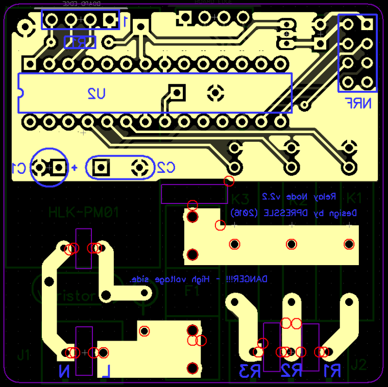
Since i dont think humans should solder SMT devices :stuck_out_tongue_winking_eye: i made this nice little non SMT board with 3 SSR relays, Hi-Link power supply, atmega328P and separated fuses for PSU and load, in a 5X5 CM board.
So far its working great, i did not put a temp fuse in the design mainly because i dont see any commercial in wall units using one, so for me i think its safe enough to not use it.
I would appreciate your comments on it, Thanks.
Main goals are:- No SMT
- 5X5 CM board
- Safe for in wall use
- Simple and cheep
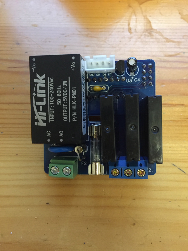
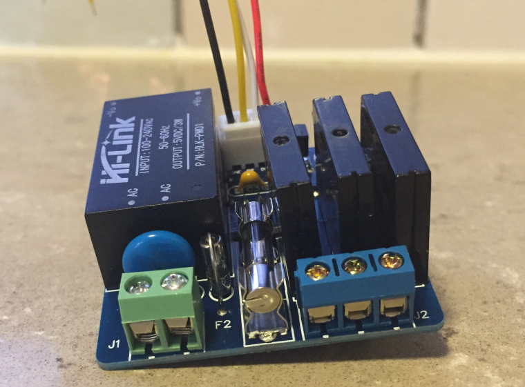
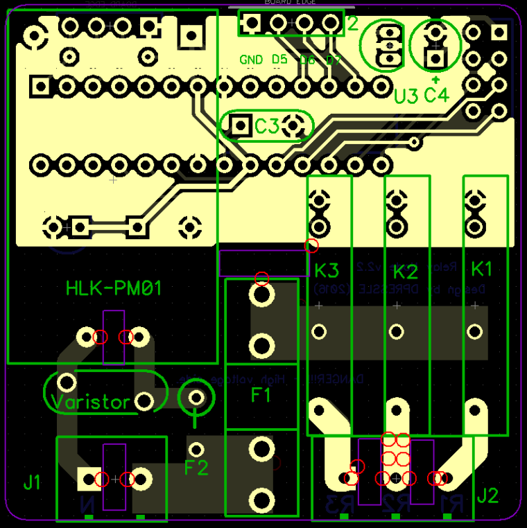
Top side design:
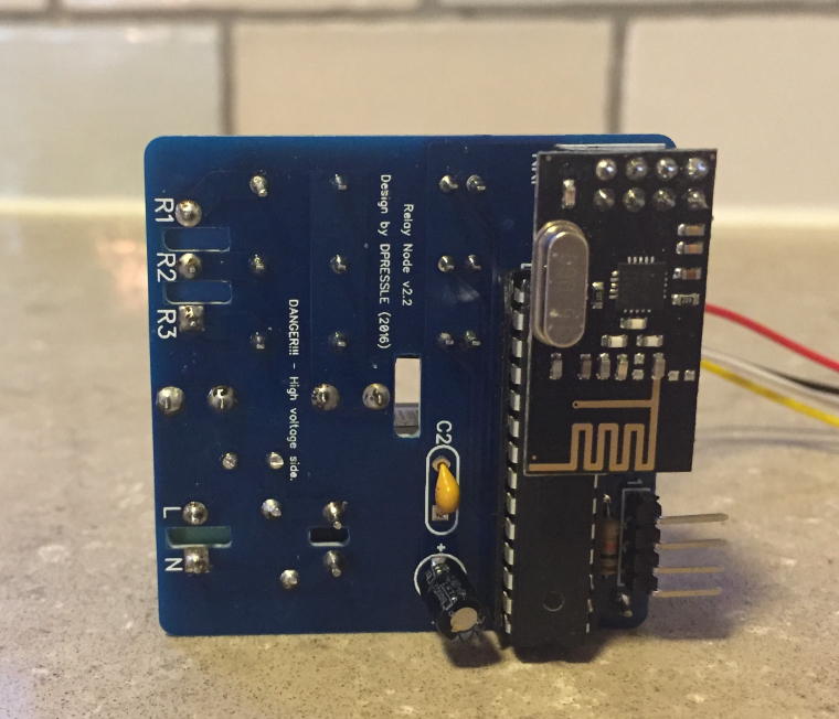
Bottom side design:
-
Since i dont think humans should solder SMT devices :stuck_out_tongue_winking_eye: i made this nice little non SMT board with 3 SSR relays, Hi-Link power supply, atmega328P and separated fuses for PSU and load, in a 5X5 CM board.
So far its working great, i did not put a temp fuse in the design mainly because i dont see any commercial in wall units using one, so for me i think its safe enough to not use it.
I would appreciate your comments on it, Thanks.
Main goals are:- No SMT
- 5X5 CM board
- Safe for in wall use
- Simple and cheep
Top side design:
Bottom side design:
-
Hello,
nice design with some care for safety !
If possible, I would suggest to connect A4/A5 to the connector, so it would be possible to use (for example) an i2c touchpad, to command the 3 relays and more, for example mpr121 can manage a mix of touchpads and leds. In case of managing leds, of course a Vcc connector would be necessary too as the last input pins would not provide enough current.
Analog pins A0-A5 can be used as digital pins if needed so it could still work as you designed it at the moment with physical switches.On thing that is annoying me also with some designs, is that when you want to use in ceiling to connect directly to ligh bulbs, you need to use connectors/wago to "duplicate" neutral because the board only provides live. If possible you should move J1 to the right, and put holes to add extra 2x connector on the left if people want to have neutral without external connectors, it will give a much cleaner result when connected instead of a mess of wires. I think it's possible to do it if you move the varistor to the left, and change orientation of F2.
-
Thanks, should be under 10USD in parts.
BTW, same design but for roller shutter is on the way -
Hi, dpressle. Thanks for your work?
One Question. Can i connect a normal light switch to it? So that i can turn on the lights with the switch and this node?@artipi Sure you can that is the whole point of the D5, D6, D7 connection.
You just need to take the GND and each of these digital inputs and connect them to the switch (NO high voltage in the switch only GND and digital input), each one of then controls one relay.
-
@dpressle said in Another simple (No SMT) relay actuator:
@breimann Thanks, does any one want link to dirtypcbs?
Hi!
Yes, please send links, really good design!
Regards Rickard
-
@MLs Its in the OpenHardware page see the Source Code tab:
OpenHardwareNote its intended to work with "Home Assistant" HA, some depending on your controller some changes might be needed.