MYSBootloader 1.3pre2 testing


  • Admin

    Hi all,
    Here is the second pre-release of MYSBootloader 1.3 for testing purposes.

    Download here. Thanks for your feedback.

    MYSBootloader 1.3pre2 (1.3NS)

    • requires MySensors 2.0.x
    • supports OTA FW AND serial FW updates
    • no external flash needed for OTA FW updates (thus, offline update)
    • communicates via assigned parent node (if found)
    • 2kb bootloader size
    • bootloader commands removed (size constraints, STK500 code instead)
    • nRF24 (Channel 76, base address 0xA8A8E1FC00, data rate 250kbs)
    • serial uploads: 115200 baud (16Mhz), 38400 (8Mhz) or 9600 (1Mhz)

    Using Arduino IDE 1.6.12:

    Add these lines (or copy from included add_to_boards.txt file) to the boards.txt file in your Arduino IDE installation folder:

    
    ##############################################################
    
    MYSBL13.name=ATmega328 with MYSBootloader
    
    MYSBL13.upload.tool=avrdude
    MYSBL13.upload.protocol=arduino
    
    MYSBL13.bootloader.tool=avrdude
    MYSBL13.bootloader.unlock_bits=0x3F
    MYSBL13.bootloader.lock_bits=0x0F
    
    MYSBL13.build.mcu=atmega328p
    MYSBL13.build.board=AVR_PRO
    MYSBL13.build.core=arduino
    MYSBL13.build.variant=standard
    
    ## Arduino with MYSBootloader 1.3pre
    ## -------------------------------------------------
    MYSBL13.menu.cpu.16MHzatmega328=ATmega328 16MHz (XTAL, BOD1V8)
    MYSBL13.menu.cpu.16MHzatmega328.upload.maximum_size=30720
    MYSBL13.menu.cpu.16MHzatmega328.upload.maximum_data_size=2048
    MYSBL13.menu.cpu.16MHzatmega328.upload.speed=115200
    MYSBL13.menu.cpu.16MHzatmega328.bootloader.low_fuses=0xFF
    MYSBL13.menu.cpu.16MHzatmega328.bootloader.high_fuses=0xDA
    MYSBL13.menu.cpu.16MHzatmega328.bootloader.extended_fuses=0x06
    MYSBL13.menu.cpu.16MHzatmega328.bootloader.file=MYSBootloader/MYSBL13pre_atmega328_16Mhz.hex
    MYSBL13.menu.cpu.16MHzatmega328.build.mcu=atmega328p
    MYSBL13.menu.cpu.16MHzatmega328.build.f_cpu=16000000L
    
    MYSBL13.menu.cpu.8MHzatmega328=ATmega328 8MHz (RC, BOD1V8)
    MYSBL13.menu.cpu.8MHzatmega328.upload.maximum_size=30720
    MYSBL13.menu.cpu.8MHzatmega328.upload.maximum_data_size=2048
    MYSBL13.menu.cpu.8MHzatmega328.upload.speed=38400
    MYSBL13.menu.cpu.8MHzatmega328.bootloader.low_fuses=0xE2
    MYSBL13.menu.cpu.8MHzatmega328.bootloader.high_fuses=0xDA
    MYSBL13.menu.cpu.8MHzatmega328.bootloader.extended_fuses=0x06
    MYSBL13.menu.cpu.8MHzatmega328.bootloader.file=MYSBootloader/MYSBL13pre_atmega328_8Mhz.hex
    MYSBL13.menu.cpu.8MHzatmega328.build.mcu=atmega328p
    MYSBL13.menu.cpu.8MHzatmega328.build.f_cpu=8000000L
    
    MYSBL13.menu.cpu.1MHzatmega328=ATmega328 1MHz (RC/8, BOD1V8)
    MYSBL13.menu.cpu.1MHzatmega328.upload.maximum_size=30720
    MYSBL13.menu.cpu.1MHzatmega328.upload.maximum_data_size=2048
    MYSBL13.menu.cpu.1MHzatmega328.upload.speed=9600
    MYSBL13.menu.cpu.1MHzatmega328.bootloader.low_fuses=0x62
    MYSBL13.menu.cpu.1MHzatmega328.bootloader.high_fuses=0xDA
    MYSBL13.menu.cpu.1MHzatmega328.bootloader.extended_fuses=0x06
    MYSBL13.menu.cpu.1MHzatmega328.bootloader.file=MYSBootloader/MYSBL13pre_atmega328_1Mhz.hex
    MYSBL13.menu.cpu.1MHzatmega328.build.mcu=atmega328p
    MYSBL13.menu.cpu.1MHzatmega328.build.f_cpu=1000000L
    
    ##############################################################
    

    Please read this excellent guide written by @scalz about MySensors OTA programming.

    In brief:

    Copy bootloader *.hex files (from Bootloader folder) to the [Arduino IDE installation folder]/hardware/arduino/avr/bootloaders/MYSBootloader/

    Restart Arduino IDE, choose under Tools | Board | ATmega328 with MYSBootloader |, select correct board under Processor tab. Connect USBasp to sensor node and select Tools | Programmer | USBasp and hit "Burn Bootloader"
    Please use the AVR fuse calculator to retrieve the individual fuse settings. If you need to change frequency, BOD or other settings, change the fuse settings based on the fuse calculator.

    OTA FW updates using MYSController 3315 (included) (refer to @scalz's guide😞

    Copy Arduino FW .hex file to MYSController/Firmware folder and edit firmware_config.csv file according to the existing lines.

    Hit "Refresh Repo" in MYSController and the newly copied firmware should appear in the Assign FW dropdown list, ready to be uploaded.

    Read this thread for discussions on MYSBootloader 1.3pre1

    Have fun!


  • Flashed one of my boards with new bootloader. Signing fails. Uploaded and ran the personalisation again and then the original sketch, still "signature verification failed".

    Edit, Went back to standard bootloader, cant get signing to work again. Hm. Doing something wrong maybe.

    Edit 2, got it working again. Flashing bootloaders, clearing eeprom, personalisation, doing it many times and at last it started to work again with (soft) signing enabled. Have not been able to upgrade my sketch using OTA yet..

    How would I configure the boards.txt for my boards with 3.3v, 8MHz and 8MHz external crystal? I'm really new to all this. Never worked with arduinos before and I don't fully understans the fuse calculator yet. 😉


  • Admin

    @NiklasO you can use the internal RC oscillator (that is 8Mhz), no need to use external XTAL. For AVR fuse calculator, refer to http://www.engbedded.com/fusecalc/ or http://eleccelerator.com/fusecalc/fusecalc.php?chip=atmega328p and the documentation therein.


  • This post is deleted!

  • Hero Member

    I read somewhere that there has been a wireless bootloader for the RFM69 "under development" now for some time, and that it can work without using additional external memory chips (such as a winbond memory chip). Is that true, and if so, has the development completed or is it still unreleased?


  • @tekka

    Finally some action here again! Yeah!
    Any chance we can get our hands on the source so that we can change channels/power and finetune led status and such?


  • This post is deleted!


  • @tekka said:

    @NiklasO you can use the internal RC oscillator (that is 8Mhz), no need to use external XTAL. For AVR fuse calculator, refer to http://www.engbedded.com/fusecalc/ or http://eleccelerator.com/fusecalc/fusecalc.php?chip=atmega328p and the documentation therein.

    I don't understand the fusecalc yet. I don't know all the terms used on that calc page or how it really works but I'm learning I guess. 😉 The Pro Mini clones i got from eBay has this extremely small external 8 MHz (for 3.3V) and 16MHz (for 5V) crystal/oscillator/resonator or what they are called. Why is it there if not needed? Genuine interested here.


  • Hero Member

    So, I gather there is no RFM69 version?


  • @mannkind what other software do you use for ota firmware update?
    thanks


  • Hero Member

    Not getting an answer here. Should I be asking the question somewhere else?


  • This post is deleted!


  • @mannkind thank you for your reply. I don't want to get you in trouble regarding the rules. i don't feel it is against the rules to promote open source or contribution around mysensors if it makes the journey more enjoyable. maybe a mod or admin can pitch in and clarify in any case.
    I understand that the gateway role is to open up integration with other controllers (and we have quite many thanks to that)
    The problem i am trying to wrap my head around is to have mysensors network attached to my current controller, and ideally be able to update over the air the sketches. how can i begin doing that? i am ready to use 2 or more controller (mycontroller or myscontroller or...), 2 ore more gateways and even maybe have the nodes on two different rf channels.

    Basically, what is the recommended way to achieve that, while having for the time being at least, another controller attached.?


  • Hello! Will there be a chance to change the radio channel used for the bootloader OTA process?


  • @mannkind : thank you for your message. I'll give that a go later on.

    @tekka , @anyone 🙂
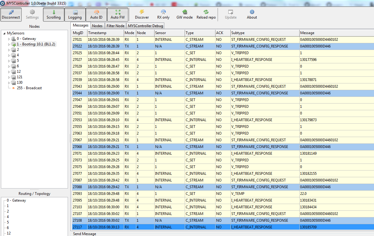
    I am trying to make this work using MYSController (from MYSBootloader_V13pre2/). I've followed the instructions above from @tekka, but it feels like the OTA process kicks around quite quick, then it seems to block in a loop

     [2016-10-17 23:09:29.821 Info] RX	1;255;4;0;0;0A0001005000D4460102
     [2016-10-17 23:09:29.821 Info] INFO	BL version=258
     [2016-10-17 23:09:29.821 Info] INFO	Send FW info to node 1: type=A, version=1, blocks=0x0050, CRC=0x46D4
     [2016-10-17 23:09:29.822 Info] TX	1;0;4;0;1;0A0001005000D446
    

    I'll try to keep it going all night, but here are my full log till now.
    Any idea what is going wrong?
    0_1476738954886_MySensors_20161017-230018.log


  • This post is deleted!

  • Admin

    @jmkhael Looks like a bad radio connection (GW too close / far, interference, power) What happens if you upload the FW via serial link?


  • @mannkind : thanks for the clarifications. My problem is that the node seems to hang at the booting phase in MYSController sa per the screenshot.

    @tekka that should be it (gw in the 50 cm range). I'll try more tests and get back here in any case.

    @mannkind, @tekka: How do we interpret the OTA logs?

    0_1476786275039_MYSController 1.0.png


  • @tekka: it was probably a mix of power/distance. when change these two parameters, OTA went fine. thank you

    What is the best way to handle OTA for sleeping nodes? is there something else todo besides setting the property under settings in MYSController? Do I need to powercycle the node or will MYSController kicks in when the node sleeps/smartSleeps?
    thank you for your time


  • Admin

    @jmkhael MYSController will reboot the node as soon as it wakes up, sends and processes incoming messages.


  • @tekka my node wakes up every two minutes (or on pir movement) sends some messages (temperature, light level...) and sleeps right away. will MYSController be able to do that in this small time window? is there something i can code to help it? (heartBeat, wait, smartSomething?)
    (as i saw during my few tests, i had to powercycle my node, maybe i wasn't patient enough :))


  • Admin

    @jmkhael place smartSleep() instead of sleep(), before sending any values to the controller - MYSController will pick this up and send a reboot command. Also, you need to mark the node as battery-powered/sleeping node...


  • Just tried with this release, works great (had no problem with previous release)

    The only drawback is the packet bitrate, around 40 per minute with 45 bytes each.
    It takes 1h to flash a node. few minutes, just make sure of your wiring as this is a very intensive process compared to node's standard radio use.

    Here is a flash running on a test network:

    snip

    Can we update many nodes at the same time ? haven't tried


  • Admin

    @JCLB This is unusual. A regular sketch ~20kB takes ~2mins. Maybe you are having issues with power supply, bad clones, or other sources of interference.


  • I can now gets dozen of packets at once, then hold, continues...depending of how I press the wires on radio side 😓
    It's a wiring problem, will try this weekend with a soldered node.

    Thank you


  • Admin

    @JCLB Thanks for reporting, I'm using short dupont cables or have the radio fixed on a PCB.


  • I have also problem with speed of the upload. I get about 1 packet per 3 seconds. Is there a something in the code for the bootloader that has a waitingtime of 3 seconds? And if so, because of what? From that info we might be able to tell if it's a reception problem of the node or the gateway.


  • @tekka Thank you for great job on MYSBootloader. It works fine for me. Currently I'm testing it and have few questions.

    • Please can you provide source code? Maybe then I can answer my questions myself 🙂
    • Software signing doesn't work after firmware is uploaded. EEPROM is cleared. Is it possible to restore shared key HMAC after firmware is stored?
    • Is possible to send firmware with signing to prevent loading from fake gateway? I thing signing of available firmware version and firmware CRC is enough ..?

    Thank you for answers.


  • I have changed the fuse settings for my setup. I don't know if it makes any difference but there is a fuse for "Preserve EEPROM memory through the Chip Erase cycle". Was noticing that my sensors was getting a new id every time I did some changes in my sketches and flashed using "Upload with programmer". I have not succeeded with OTA flashing yet.
    I also use the external crystal present on the Pro Mini. Using 0xFF, 0xD2 and 0xFE.
    Probably only used when programming using ICSP.

    MYSBL13.menu.cpu.8MHzatmega328=ATmega328 8MHz (XTAL, BOD1V8)
    MYSBL13.menu.cpu.8MHzatmega328.upload.maximum_size=30720
    MYSBL13.menu.cpu.8MHzatmega328.upload.maximum_data_size=2048
    MYSBL13.menu.cpu.8MHzatmega328.upload.speed=38400
    MYSBL13.menu.cpu.8MHzatmega328.bootloader.low_fuses=0xFF
    MYSBL13.menu.cpu.8MHzatmega328.bootloader.high_fuses=0xD2
    MYSBL13.menu.cpu.8MHzatmega328.bootloader.extended_fuses=0xFE
    MYSBL13.menu.cpu.8MHzatmega328.bootloader.file=MYSBootloader/MYSBL13pre_atmega328_8Mhz.hex
    MYSBL13.menu.cpu.8MHzatmega328.build.mcu=atmega328p
    MYSBL13.menu.cpu.8MHzatmega328.build.f_cpu=8000000L


  • @NiklasO I'm using Arduino Mini 5V, 16Mhz with fuses as you have. Except BODLEVEL 2.7V and EEPROM Cleared. OTA works fine, 21kB hex file is sent in cca 2-5 minutes (very depends on count of wrong packets, without 47uF capacitor on NRF24 or with low power supply it takes about 2 hours 🙂 ). I started with MYSController and small and easy Blink.ino.hex from MYSController distribution. Now I use MyController and own firmwares...


  • @pku if your keys are in the sketch everything will work for signing.
    #define MY_SOFT_HMAC_KEY XXX... //signing key
    #define MY_AES_KEY XXX... // if you use encryption
    Of course if you want to use whitelisting then you need to compile each node sketch separately with it's serial.

    @NiklasO
    Personally I set the node ID manually to avoid this
    #define MY_NODE_ID 30 // Sets a static id for a node
    And I group tens so all my 3X nodes are in kitchen, 4X in office, 11X in bedroom 1 and so on.

    I would love to see a proxy mode in MYSController, in order to interface between a controller that doesn't support OTA and an Ethernet gateway 😍

    Let say your LAN is the following:

    • MySensors gateway 192.168.0.1
    • controller (raspberry + Domoticz or else) 192.168.0.2
    • PC with MYSController 192.168.0.3

    Whenever you need to update a node, you launch MYSController but don't connect to the gateway, then you tells Domoticz .2 to connect to MYSController .3 instead of the gateway .1, at this point MYSController starts relaying everything between Domoticz and the gateway + provides you the ability to update a node.

    When you want to get back to normal operations, you set back 192.168.0.1 on Domoticz, MYSController receives a TCP reset and ends it's session with Domoticz and stop the session with the gateway.

    We would get a minimum downtime and can could use MYSController to update nodes and debug traffic while letting the normal controller...controlling


  • @NiklasO
    Personally I set the node ID manually to avoid this
    #define MY_NODE_ID 30 // Sets a static id for a node
    And I group tens so all my 3X nodes are in kitchen, 4X in office, 11X in bedroom 1 and so on.

    Ah, yes. Setting static id sound like a solution to my problem. Thanks.


  • @JCLB said:

    @pku if your keys are in the sketch everything will work for signing.
    #define MY_SOFT_HMAC_KEY XXX... //signing key
    #define MY_AES_KEY XXX... // if you use encryption
    Of course if you want to use whitelisting then you need to compile each node sketch separately with it's serial.

    but that would give a listener your full MY_SOFT_HMAC_KEY and signing would be useless in future. Therefor it is better to write the key in eeprom with cable and later only update firmware without key via OTA.


  • @Anduril

    1. I agree, keys located in sketch can be used as workaround only, because the security is broken.
    2. But I'm interesting in key located in EEPROM. How it is work during flashing? If Clear EEPROM fuse is not set then everybody can take my outside node, put his own firmware and it will work with keys from EEPROM. It is again a security issue (of course he must have physical access to my node).
      I thing it should work with this scenario:
    • reguest for new firmware
    • copy key, serial and rsa into RAM
    • flash new firmware (with fuse clear EEPROM)
    • copy key, serial and rsa back into EEPROM

    What do you thing?


  • For a node that is physically accessable it is realy hard. First: does this node needs signing? For sensor data you don't need in most cases. Maybe you should use the hardware chip, there you can't read out the key and if it was locked you also can't change it.
    If you still need to use softsigning you could use whitelisting and revoke the whitelist-entry in case of corruption.


  • Hello,

    I am trying to use MYSController with MYSBootloader 1.3pre2 to reassign a node's ID, and I cannot make it work.
    I've tried to check/uncheck the Auto ID toggle/tried to use the MYSBootloader CMDs/Assign ID and setting a new one to no avail.

    After that, when it reboots, the node reask for it's firmware, and MYSController re-uploads it, but the node keeps the old ID from the EEProm. (note that the sketch don't hardcode the node's ID).

    I'd like to keep the ID management free (i.e. do not hardcode all my node's IDs of course)

    How can I do that?

     [2016-10-21 13:41:33.318 Info] CLICK	Reassign ID from 1 to 20
     [2016-10-21 13:41:33.319 Info] TX	1;0;3;0;13;0
     [2016-10-21 13:41:33.364 Info] RX	0;255;3;0;9;!TSP:MSG:SEND 0-0-1-1 s=0,c=3,t=13,pt=0,l=1,sg=0,ft=0,st=fail:0
     [2016-10-21 13:41:37.886 Info] RX	0;255;3;0;9;TSP:MSG:READ 4-4-0 s=255,c=3,t=22,pt=5,l=4,sg=0:155561124
     [2016-10-21 13:41:37.886 Info] RX	4;255;3;0;22;155561124
     [2016-10-21 13:41:42.855 Info] RX	0;255;3;0;9;TSP:MSG:READ 2-2-0 s=1,c=1,t=16,pt=0,l=1,sg=0:0
     [2016-10-21 13:41:42.857 Info] RX	2;1;1;0;16;0
     [2016-10-21 13:41:46.623 Info] RX	0;255;3;0;9;TSP:MSG:READ 8-5-0 s=2,c=1,t=16,pt=0,l=1,sg=0:0
     [2016-10-21 13:41:46.625 Info] RX	8;2;1;0;16;0
     [2016-10-21 13:41:47.899 Info] RX	0;255;3;0;9;TSP:MSG:READ 8-5-0 s=3,c=1,t=23,pt=2,l=2,sg=0:80
     [2016-10-21 13:41:47.901 Info] RX	8;3;1;0;23;80
     [2016-10-21 13:41:50.491 Info] RX	0;255;3;0;9;TSP:MSG:READ 4-4-0 s=1,c=1,t=0,pt=7,l=5,sg=0:22.0
     [2016-10-21 13:41:50.494 Info] RX	0;255;3;0;9;TSP:MSG:ACK msg
     [2016-10-21 13:41:50.540 Info] RX	0;255;3;0;9;!TSP:MSG:SEND 0-0-4-4 s=1,c=1,t=0,pt=7,l=5,sg=0,ft=0,st=fail:22.0
     [2016-10-21 13:41:50.540 Info] RX	4;1;1;0;0;22.0
     [2016-10-21 13:41:50.570 Info] RX	0;255;3;0;9;TSP:MSG:READ 4-4-0 s=255,c=3,t=22,pt=5,l=4,sg=0:155562401
     [2016-10-21 13:41:50.570 Info] RX	4;255;3;0;22;155562401
     [2016-10-21 13:41:57.014 Info] RX	0;255;3;0;9;TSP:SANCHK:OK
     [2016-10-21 13:42:02.832 Info] RX	0;255;3;0;9;TSP:MSG:READ 4-4-0 s=255,c=3,t=22,pt=5,l=4,sg=0:155563404
     [2016-10-21 13:42:02.832 Info] RX	4;255;3;0;22;155563404
     [2016-10-21 13:42:20.453 Info] RX	0;255;3;0;9;TSP:MSG:READ 1-1-0 s=255,c=3,t=22,pt=5,l=4,sg=0:4712
     [2016-10-21 13:42:20.453 Info] RX	1;255;3;0;22;4712
     [2016-10-21 13:42:20.453 Info] CHILD	New child discovered, node id=1, child id=internal
     [2016-10-21 13:42:20.951 Info] RX	0;255;3;0;9;TSP:MSG:READ 1-1-0 s=2,c=1,t=16,pt=0,l=1,sg=0:0
     [2016-10-21 13:42:20.953 Info] RX	1;2;1;0;16;0
     [2016-10-21 13:42:20.953 Info] CHILD	New child discovered, node id=1, child id=2
     [2016-10-21 13:42:21.954 Info] RX	0;255;3;0;9;TSP:MSG:READ 1-1-0 s=3,c=1,t=23,pt=2,l=2,sg=0:42
     [2016-10-21 13:42:21.956 Info] RX	1;3;1;0;23;42
     [2016-10-21 13:42:21.956 Info] CHILD	New child discovered, node id=1, child id=3
     [2016-10-21 13:42:27.773 Info] RX	0;255;3;0;9;TSP:MSG:READ 4-4-0 s=255,c=3,t=22,pt=5,l=4,sg=0:155565680
     [2016-10-21 13:42:27.774 Info] RX	4;255;3;0;22;155565680
     [2016-10-21 13:42:40.382 Info] RX	0;255;3;0;9;TSP:MSG:READ 4-4-0 s=255,c=3,t=22,pt=5,l=4,sg=0:155566954
     [2016-10-21 13:42:40.382 Info] RX	4;255;3;0;22;155566954
    
    Starting sensor (RNNNA-, 2.0.0)
    TSM:INIT
    TSM:RADIO:OK
    TSP:ASSIGNID:OK (ID=1)
    TSM:FPAR
    TSP:MSG:SEND 1-1-255-255 s=255,c=3,t=7,pt=0,l=0,sg=0,ft=0,st=bc:
    TSP:MSG:READ 5-5-1 s=255,c=3,t=8,pt=1,l=1,sg=0:1
    TSP:MSG:FPAR RES (ID=5, dist=1)
    TSP:MSG:PAR OK (ID=5, dist=2)
    TSP:MSG:READ 0-0-1 s=255,c=3,t=8,pt=1,l=1,sg=0:0
    TSP:MSG:FPAR RES (ID=0, dist=0)
    TSP:MSG:PAR OK (ID=0, dist=1)
    TSM:FPAR:OK
    TSM:ID
    TSM:CHKID:OK (ID=1)
    TSM:UPL
    TSP:PING:SEND (dest=0)
    TSP:MSG:SEND 1-1-0-0 s=255,c=3,t=24,pt=1,l=1,sg=0,ft=0,st=ok:1
    TSP:MSG:READ 0-0-1 s=255,c=3,t=25,pt=1,l=1,sg=0:1
    TSP:MSG:PONG RECV (hops=1)
    TSP:CHKUPL:OK
    TSM:UPL:OK
    TSM:READY
    TSP:MSG:SEND 1-1-0-0 s=255,c=3,t=15,pt=6,l=2,sg=0,ft=0,st=ok:0100
    TSP:MSG:SEND 1-1-0-0 s=255,c=0,t=17,pt=0,l=5,sg=0,ft=0,st=ok:2.0.0
    TSP:MSG:SEND 1-1-0-0 s=255,c=3,t=6,pt=1,l=1,sg=0,ft=0,st=ok:0
    TSP:MSG:READ 0-0-1 s=255,c=3,t=15,pt=6,l=2,sg=0:0100
    TSP:MSG:READ 0-0-1 s=255,c=3,t=15,pt=6,l=2,sg=0:0100
    TSP:MSG:READ 0-0-1 s=255,c=3,t=6,pt=0,l=1,sg=0:M
    TSP:MSG:SEND 1-1-0-0 s=255,c=3,t=11,pt=0,l=12,sg=0,ft=0,st=ok:Multi Sensor
    TSP:MSG:SEND 1-1-0-0 s=255,c=3,t=12,pt=0,l=3,sg=0,ft=0,st=ok:1.0
    TSP:MSG:SEND 1-1-0-0 s=2,c=0,t=1,pt=0,l=0,sg=0,ft=0,st=ok:
    TSP:MSG:SEND 1-1-0-0 s=0,c=0,t=7,pt=0,l=0,sg=0,ft=0,st=ok:
    TSP:MSG:SEND 1-1-0-0 s=1,c=0,t=6,pt=0,l=0,sg=0,ft=0,st=ok:
    TSP:MSG:SEND 1-1-0-0 s=3,c=0,t=16,pt=0,l=0,sg=0,ft=0,st=ok:
    Request registration...
    TSP:MSG:SEND 1-1-0-0 s=255,c=3,t=26,pt=1,l=1,sg=0,ft=0,st=ok:2
    TSP:MSG:READ 0-0-1 s=255,c=3,t=27,pt=1,l=1,sg=0:1
    Node registration=1
    Init complete, id=1, parent=0, distance=1, registration=1
    TSP:MSG:SEND 1-1-0-0 s=2,c=1,t=16,pt=0,l=1,sg=0,ft=0,st=ok:0
    TSP:MSG:SEND 1-1-0-0 s=3,c=1,t=23,pt=2,l=2,sg=0,ft=0,st=ok:54


  • Hi! Great work!
    I have a small question: How does your Bootloader know which channel to listen on?


  • @JamesT42
    Hi, it is hardcoded within the bootloader: nRF24 (Channel 76, base address 0xA8A8E1FC00, data rate 250kbs)


  • Admin

    @jmkhael Bootloader commands have been removed due to size constraints (see initial post). If you want to change the node ID you can send a C_INTERNAL / I_ID_RESPONSE / <new ID> message to an actively listening node.


  • Admin

    @JamesT42 Thanks. As @pku pointed out, this is hardcoded. With the final release of MYSBootloader and its source code, everybody will be able to adjust settings and recompile the bootloader as needed.


  • @tekka : fair enough, i should read better next time 🙂
    i'll try the way you suggest. thank you.


  • hi tekka
    I had to change the channel of the NRF from 76 to 0 here because of massive disturbances . Unfortunately, no OTA works now. Is it possible to create a modified bootloader that works with 0 instead of 76? Sorry for the bad english it is translated with google.


  • Hi, thank for the great work.
    I also use a different Channel, in fact I have 3 area with 3 differents Channels.
    Do you have a plan about source code release date ?


  • Is there a way to debug the bootloader should it print debug information and how to see this?


  • This post is deleted!


  • Hi,
    I just start to test this bootloader...
    I use an ATmega328p on breadboard with no external clock, with nRF24 and somes sensors.
    Firmware Upload (by usbasp) and Run is ok, Send/Receive Data is ok too , but when I ask a reboot (with MYSController 1.0.0beta), my node enter in sort of strange start loop...
    My Fuse settings :

    bootloader.unlock_bits=0x3F
    bootloader.lock_bits=0x0F
    bootloader.low_fuses=0x62
    bootloader.high_fuses=0xDA
    bootloader.extended_fuses=0x07
    

    Node debug Trace :

    .....
    TSP:MSG:READ 0-0-4 s=2,c=1,t=0,pt=7,l=5,sg=0:28.18
    TSP:MSG:READ 0-0-4 s=1,c=1,t=1,pt=7,l=5,sg=0:38.28
    TSP:MSG:READ 0-0-4 s=0,c=3,t=13,pt=0,l=1,sg=0:0
    StartiStartiStartiStartiþStartiþStartiþStartiStartiþStartiþStartiþStartiþStartiþStartiþStartiþStartiþStartiþStartiþStartiþStartiþStartiþStartiþStartiþStartiþStartiþStartiþStartiþStartiþStartiþStartiþStartiþStartiþStartiþStartiþStartiþ
    ....
    

    The "Startiþ" text is the first char of the first text printed by bootloader at start : "Starting sensor....."
    Have you an idea ?

    Thanks


  • Admin

    Please provide additional information such as library version, full debug log of your GW and node. Which bootloader/version are you using?


  • @tekka Thanks for you response
    For gateway :
    Raspberrry PI Gateway in Ethernet mode
    Protocol version : 2.0.1-beta

    For Node :
    I use bootloader : MYSBL13pre_atmega328_1Mhz.hex
    Inital Sketch do nothing 🙂 :

    #define MY_DEBUG
    #define MY_BAUD_RATE 9600
    #define MY_RADIO_NRF24
    #define MY_OTA_FIRMWARE_FEATURE
    #define MY_NODE_ID 1
    
    #include <MySensors.h>
    
    void presentation(){
      sendSketchInfo("MyFirstBoard", "0.0.2", true);
    }
    
    void setup() {
    }
    
    void loop() {
      wait(5000);
    }
    

    Test Case: Start Gateway, Connect MYSController 1.0.0beta, then start my sensor, after init complete, click reboot in MYSController
    Gateway Log :

    mysgw: Starting gateway...
    mysgw: Protocol version - 2.0.1-beta
    mysgw: MCO:BGN:INIT GW,CP=RNNG---,VER=2.0.1-beta
    mysgw: TSF:LRT:OK
    mysgw: TSM:INIT
    mysgw: TSM:INIT:TSP OK
    mysgw: TSM:INIT:GW MODE
    mysgw: TSM:READY
    mysgw: Listening for connections on 0.0.0.0:5003
    mysgw: MCO:REG:NOT NEEDED
    mysgw: MCO:BGN:STP
    mysgw: MCO:BGN:INIT OK,ID=0,PAR=0,DIS=0,REG=1
    
    mysgw: New connection from 10.31.10.59
    mysgw: Client 0 connected
    
    mysgw: TSF:MSG:READ,1-1-255,s=255,c=3,t=7,pt=0,l=0,sg=0:
    mysgw: TSF:MSG:BC
    mysgw: TSF:MSG:FPAR REQ,ID=1
    mysgw: TSF:PNG:SEND,TO=0
    mysgw: TSF:CKU:OK
    mysgw: TSF:MSG:GWL OK
    mysgw: TSF:MSG:SEND,0-0-1-1,s=255,c=3,t=8,pt=1,l=1,sg=0,ft=0,st=OK:0
    mysgw: TSF:MSG:READ,1-1-0,s=255,c=3,t=24,pt=1,l=1,sg=0:1
    mysgw: TSF:MSG:PINGED,ID=1,HP=1
    mysgw: TSF:MSG:SEND,0-0-1-1,s=255,c=3,t=25,pt=1,l=1,sg=0,ft=0,st=OK:1
    mysgw: TSF:MSG:READ,1-1-0,s=255,c=4,t=0,pt=6,l=10,sg=0:FFFFFFFFFFFFFFFF0300
    mysgw: TSF:MSG:READ,1-1-0,s=255,c=3,t=15,pt=6,l=2,sg=0:0100
    mysgw: TSF:MSG:SEND,0-0-1-1,s=255,c=3,t=15,pt=6,l=2,sg=0,ft=0,st=OK:0100
    mysgw: TSF:MSG:READ,1-1-0,s=255,c=0,t=17,pt=0,l=5,sg=0:2.0.0
    mysgw: TSF:MSG:READ,1-1-0,s=255,c=3,t=6,pt=1,l=1,sg=0:0
    mysgw: Client 0: 1;255;3;0;6;M
    mysgw: TSF:MSG:SEND,0-0-1-1,s=255,c=3,t=6,pt=0,l=1,sg=0,ft=0,st=OK:M
    mysgw: TSF:MSG:READ,1-1-0,s=255,c=3,t=11,pt=0,l=12,sg=0:MyFirstBoard
    mysgw: TSF:MSG:ACK REQ
    mysgw: TSF:MSG:SEND,0-0-1-1,s=255,c=3,t=11,pt=0,l=12,sg=0,ft=0,st=OK:MyFirstBoard
    mysgw: TSF:MSG:READ,1-1-0,s=255,c=3,t=12,pt=0,l=5,sg=0:0.0.2
    mysgw: TSF:MSG:ACK REQ
    mysgw: TSF:MSG:SEND,0-0-1-1,s=255,c=3,t=12,pt=0,l=5,sg=0,ft=0,st=OK:0.0.2
    mysgw: TSF:MSG:READ,1-1-0,s=255,c=3,t=26,pt=1,l=1,sg=0:2
    mysgw: TSF:MSG:SEND,0-0-1-1,s=255,c=3,t=27,pt=1,l=1,sg=0,ft=0,st=OK:1
    
    mysgw: Client 0: 1;0;3;0;13;0
    mysgw: TSF:MSG:SEND,0-0-1-1,s=0,c=3,t=13,pt=0,l=1,sg=0,ft=0,st=OK:0


    NodeLog :

    Starting sensor (RNONA-, 2.0.0)
    TSM:INIT
    TSM:RADIO:OK
    TSP:ASSIGNID:OK (ID=1)
    TSM:FPAR
    TSP:MSG:SEND 1-1-255-255 s=255,c=3,t=7,pt=0,l=0,sg=0,ft=0,st=bc:
    TSM:FPAR
    TSP:MSG:SEND 1-1-255-255 s=255,c=3,t=7,pt=0,l=0,sg=0,ft=0,st=bc:
    TSP:MSG:READ 0-0-1 s=255,c=3,t=8,pt=1,l=1,sg=0:0
    TSP:MSG:FPAR RES (ID=0, dist=0)
    TSP:MSG:PAR OK (ID=0, dist=1)
    TSM:FPAR:OK
    TSM:ID
    TSM:CHKID:OK (ID=1)
    TSM:UPL
    TSP:PING:SEND (dest=0)
    TSP:MSG:SEND 1-1-0-0 s=255,c=3,t=24,pt=1,l=1,sg=0,ft=0,st=ok:1
    TSP:MSG:READ 0-0-1 s=255,c=3,t=25,pt=1,l=1,sg=0:1
    TSP:MSG:PONG RECV (hops=1)
    TSP:CHKUPL:OK
    TSM:UPL:OK
    TSM:READY
    TSP:MSG:SEND 1-1-0-0 s=255,c=4,t=0,pt=6,l=10,sg=0,ft=0,st=ok:FFFFFFFFFFFFFFFF0300
    TSP:MSG:SEND 1-1-0-0 s=255,c=3,t=15,pt=6,l=2,sg=0,ft=0,st=ok:0100
    TSP:MSG:SEND 1-1-0-0 s=255,c=0,t=17,pt=0,l=5,sg=0,ft=0,st=ok:2.0.0
    TSP:MSG:SEND 1-1-0-0 s=255,c=3,t=6,pt=1,l=1,sg=0,ft=0,st=ok:0
    TSP:MSG:READ 0-0-1 s=255,c=3,t=15,pt=6,l=2,sg=0:0100
    TSP:MSG:READ 0-0-1 s=255,c=3,t=6,pt=0,l=1,sg=0:M
    TSP:MSG:SEND 1-1-0-0 s=255,c=3,t=11,pt=0,l=12,sg=0,ft=0,st=ok:MyFirstBoard
    TSP:MSG:SEND 1-1-0-0 s=255,c=3,t=12,pt=0,l=5,sg=0,ft=0,st=ok:0.0.2
    Request registration...
    TSP:MSG:SEND 1-1-0-0 s=255,c=3,t=26,pt=1,l=1,sg=0,ft=0,st=ok:2
    TSP:MSG:READ 0-0-1 s=255,c=3,t=11,pt=0,l=12,sg=0:MyFirstBoard
    TSP:MSG:READ 0-0-1 s=255,c=3,t=12,pt=0,l=5,sg=0:0.0.2
    TSP:MSG:READ 0-0-1 s=255,c=3,t=27,pt=1,l=1,sg=0:1
    Node registration=1
    Init complete, id=1, parent=0, distance=1, registration=1
    TSP:MSG:READ 0-0-1 s=0,c=3,t=13,pt=0,l=1,sg=0:0
    StartiîStartiîStartiîStartiîStartiîStartiîStartiîStartiîStartiîStartiîStartiîStartiîStartiîStartiîStartiîStartiîStartiîStartiîStartiîStartiîStartiîStartiîStartiîStartiîStartiîStartiîStartiîStartiîStartiîStartiîStartiîStartiîStartiîStartiîStartiîStartiîStartiîStartiîStartiStartiStartiStartiStartiStartiStartiStartiStartiStartiîStartiîStartiStartiStartiStartiStartiStartiStartiStartiStartiStartiStartiStartiþStartiStartiStartiStartiStartiStartiStartiStartiStartiStartiStarti
    

    Need others infos ?
    Thanks for your time


  • Admin

    @Tetnobic

    Starting sensor (RNONA-, 2.0.0)
    

    Your node is running MySensors 2.0.0 (your GW is at 2.0.1, please consider updating), also, there is no sign of MYSBootloader in your GW log - please double-check if you followed the correct procedure.
    One more thing: the startup message indicates that you enabled OTA firmware features (RNONA-) - this is not required with MYSBootloader.

    Please have a look at @scalz's OTA guide for additional information.


  • @tekka Thanks for your response
    What are the sign of MYSBootloader in GW log ?
    Can I also see any sign of MYSBootloader in Node Log ?

    I remove OTA firmware features, I now have :

    Starting sensor (RNNNA-, 2.0.0)
    

    but same problem, after receive reboot message I have a "StartiStartiStartiStartiS...." loop :(:(


  • Admin

    @Tetnobic No, you won't see anything in the node log - but in the GW log you should see somehting like:

    
    1;255;4;0;0;64000200C803948D0105


  • @tekka Hi, I found my mistake ! You were absolutely right when you said there is no sign of MYSBootloader in my GW log...
    But now I know why 🙂 :
    I use an USBasp Programmer with Arduino IDE for upload my bootloader and my sketch..., and I mistakenly thought that when I upload bootloader then sketch, it keep bootloader.....but NOT, it overwrite bootloader 😞
    I fix it by uploading the xxx.with_bootloader.hex file generated by Arduino IDE when compile.

    Sorry for the inconvenience and thank you for your help


  • @Tetnobic can this be done within the IDE? I have some nodes where I have to upload with ISP and thought to still have the bootloader, but this explains why OTA didn't work afterwards...


  • @Anduril I think you can do this without Arduino IDE...
    but how compile you code for generate sketch+bootloader ( the xxx.with_bootloader.hex file) in command line I don't know....
    For upload this file on my ATMega, I use avrdude, the same command line that ardunio IDE use, but change the .hex file...


  • Tried this bootloader.
    Have two nodes 8MHz internal, two nodes 1MHz. All run beautifully, the OTA firmware update around a minute with binaryButton sketch. But the node startup is around 7-8 seconds. And no problems uploading the sketch via serial.
    I use an UNO as an ASP to burn the bootloader and a simple USB_TTL FTDI converter to upload sketches.


  • This may be a stupid question, but I'm using the mysgateway on a Raspberry Pi as my controller which is described here:

    Building a Raspberry Pi Gateway

    The Raspberry pi runs headless and I do everything through ssh. Is there any way to use MYSBootloader using the mysgateway and initiating the OTA update using the command line?


  • Shall we all join hands and give a warm applause to @tekka for his work and pray that he'll find the time to give us a lovely christmas present. The MYSBootloader 1.3+ pushed to github 😃


  • This post is deleted!


  • @tekka pleeeease.... 🙏


  • It's been asked that the source is uploaded multiple times over the last year +, I guess it will not happen anytime soon... 😞


  • @jerseyguy1996

    You'll need a Controller to update the firmware in the nodes. I'm using MyController.org running on a RPI3 with a MySensors serial Gateway. Works great!


  • For all who have problems with serial (debug) output using MYSBootloader:
    When you burn the 8MHz bootloader, it sets avr fuses to internal 8MHz RC oscillator. This has high tolerance. The serial baudrate was only 108000baud in my case and Arduino IDE did not work.
    Setting the fuse to use the external quartz/resonator lead to 111000baud, which was close enough to 115200, to get arduino IDE to read serial data.


  • Please, can you provide source code? I need to configure radio pins (default MySensors CE and CS pins 9 and 10 are PWM so I need to connect the radio in other way). Thanks a lot!


  • Please help to debug:
    0 MCO:BGN:INIT NODE,CP=RNNNA--,VER=2.1.0-beta
    4 TSM:INIT
    4 TSF:WUR:MS=0
    12 !TSM:INIT:TSP FAIL
    14 TSM:FAIL:CNT=1
    16 TSM:FAIL:PDT


  • @Tigroenot Hi,

    TSM Transmission
    TSP Transport
    PDT Power Down

    !TSM:INIT:TSP FAIL Error during Transport initialization (Radio)
    TSM:FAILURE Error on Transmition (of course, you have a radio error)
    TSM:FAILURE:PDT Radio in Power Down (due to the error)

    Check your radio cabling. If all ok add a capacitor on radio power pins


  • The radio is not wired, it's directly soldered as a chip. I use MySensors Stable Node by @Koresh, but the nrf chips I got from China are probably counterfeit or don't work at all 🙂


  • After flasing a node with ISP (bootloader+sketch) the node will not start since the eeprom is emty (forgot to enable eeprom safe). Node needs to get a ID from controller, even if ID is defined in the sketch. After receiving a ID from controller the node starts and uses the ID from sketch.
    Any solution to overcome this?


  • Mod

    @karlheinz2000 that should not happen. Starting from empty eeprom is normal, that's what all nodes do the first time.

    Could you post debug output of the node and the gateway when it fails to use the defined id?
    Just to check: the id was defined before including MySensors.h right?


  • Attached the log file from MYSC. After activating AUTO ID the node starts. No other GW active.
    No serial output during this time.
    Node ID is defined before including .h.

    Node is flashed via ISP (Dragon) with "...with_bootloader.hex".

    0_1483653188071_MySensors_20170105-223345.log


  • Admin

    @karlheinz2000 I'm not sure I understand you correctly:
    With a cleared EEPROM, the bootloader will not know any ID defined in the sketch. Instead, the bootloader will fetch a new ID from the controller and store it in EEPROM. Once the sketch starts it will either overtake this newly assigned ID (if MY_NODE_ID == AUTO) or overwrite and use a static ID (if MY_NODE_ID != AUTO) from now on. Does this answer your question?


  • Understood.
    But if I'm not using MYSB, I can flash a sketch with defined ID and this will work instantly in the network.
    With MYSB I always have to do assign a new ID just to get the node to run the first time after flashing.
    Any chance to get MYSB to know, if a sketch is an flash?
    And start this sketch, which then will use the defined ID or request a new ID from controller and writes the eeprom?


  • Admin

    @karlheinz2000 said:

    But if I'm not using MYSB, I can flash a sketch with defined ID and this will work instantly in the network.

    Yes

    With MYSB I always have to do assign a new ID just to get the node to run the first time after flashing.

    Only true if EEPROM (i.e. ID address location) was cleared.

    Any chance to get MYSB to know, if a sketch is an flash?
    And start this sketch, which then will use the defined ID or request a new ID from controller and writes the eeprom?

    During booting, MYSBootloader calculates the FW CRC in flash and verifies it against the FW CRC stored in EEPROM (which is written after a successful OTA FW update) - if it matches, the sketch starts, if not, the bootloader remains active.


  • This post is deleted!


Suggested Topics

  • 1
  • 9
  • 6
  • 13
  • 20
  • 4
  • 3
  • 9

0
Online

11.2k
Users

11.1k
Topics

112.5k
Posts