Skip to content
  • MySensors
  • OpenHardware.io
  • Categories
  • Recent
  • Tags
  • Popular
Skins
  • Light
  • Brite
  • Cerulean
  • Cosmo
  • Flatly
  • Journal
  • Litera
  • Lumen
  • Lux
  • Materia
  • Minty
  • Morph
  • Pulse
  • Sandstone
  • Simplex
  • Sketchy
  • Spacelab
  • United
  • Yeti
  • Zephyr
  • Dark
  • Cyborg
  • Darkly
  • Quartz
  • Slate
  • Solar
  • Superhero
  • Vapor

  • Default (No Skin)
  • No Skin
Collapse
Brand Logo
  1. Home
  2. Troubleshooting
  3. Gateway Not Working

Gateway Not Working

Scheduled Pinned Locked Moved Troubleshooting
43 Posts 5 Posters 18.6k Views 2 Watching
  • Oldest to Newest
  • Newest to Oldest
  • Most Votes
Reply
  • Reply as topic
Log in to reply
This topic has been deleted. Only users with topic management privileges can see it.
  • C clippermiami

    @hek

    Sounds like the sensor end is working. i've put LEDs on the three leads defined in the sketch and there is nothing happening on any of them so I'm guessing that something basic is wrong with the Gateway.

    i've tried the capacitors and no change so far. At this point I'd think that at least one of the LEDs (Tx, TX or Error) would indicate something.

    BTW, i appreciate your patience with a newbie.

    H Offline
    H Offline
    hek
    Admin
    wrote on last edited by
    #31

    @clippermiami

    And your using the simple radio model on both ends (no amplified radio)?
    Are you really sure the radio-wiring is correct? And no lose contacts (it has happened more than once for me:) ?

    The radios also seems to be very sensitive when it comes to stability of the power feeding (sometimes). Do you have the possibility to feed them through Wall-wart/USB or something else than your computer?

    B 1 Reply Last reply
    0
    • H hek

      @clippermiami

      And your using the simple radio model on both ends (no amplified radio)?
      Are you really sure the radio-wiring is correct? And no lose contacts (it has happened more than once for me:) ?

      The radios also seems to be very sensitive when it comes to stability of the power feeding (sometimes). Do you have the possibility to feed them through Wall-wart/USB or something else than your computer?

      B Offline
      B Offline
      BulldogLowell
      Contest Winner
      wrote on last edited by
      #32

      @hek said:

      Are you really sure the radio-wiring is correct? And no lose contacts (it has happened more than once for me:) ?

      me too. More than I care to admit and more frustrating than anything.

      @clippermiami

      did you switch out the jumper wires already, too?

      1 Reply Last reply
      0
      • C Offline
        C Offline
        clippermiami
        Hero Member
        wrote on last edited by
        #33

        I think i've found the problem.

        In the instructions on mysensors.org under building the USB-Serial Gateway it says
        [code]
        Building a USB-connected Gateway

        NOTE: You must use an Arduino Nano for the USB version of the gateway. The Nano is the officially supported and tested model so if you try a different version, we cannot guarantee that the Vera will recognize it.

        Start by connecting the radio module.
        [/code]

        When you follow the link to "connecting the radio module it leads to a Arduino Pro-Mini configuration NOT a Nano. I used the radio configuration from the Ethernet gateway because it depicts the wiring for a Nano.

        I found some code on forum.micasaverde.com that was to debug the radio connection and put it in my Gateway code and it says the **radio is not connected properly. **

        So now i'm confused, what wiring IS correct for the NANO in the USB Serial Gateway?

        1 Reply Last reply
        0
        • H Offline
          H Offline
          hek
          Admin
          wrote on last edited by
          #34

          Yes, the radio wiring is different for ethernet vs serial version of the gateway.
          So, like the instructions say, when building the Serial version you should follow the guide here:
          http://www.mysensors.org/build/connect_radio

          The pin numbers is identical between pro mini and nano.

          C 1 Reply Last reply
          0
          • H hek

            Yes, the radio wiring is different for ethernet vs serial version of the gateway.
            So, like the instructions say, when building the Serial version you should follow the guide here:
            http://www.mysensors.org/build/connect_radio

            The pin numbers is identical between pro mini and nano.

            C Offline
            C Offline
            clippermiami
            Hero Member
            wrote on last edited by
            #35

            @hek As I recall the difference is in pins for CE/CSN (from memory here so I may be wrong) in which case my radio is in fact wired incorrectly as it used the Nano pinout from the Ethernet Gateway. I shall fix it and hopefully everything will start to play together. (Fingers, toes, legs, eyes crossed :-) )

            1 Reply Last reply
            0
            • C Offline
              C Offline
              clippermiami
              Hero Member
              wrote on last edited by
              #36

              Well, that didn't do it either. i do however now have a ERR LED indication on SOLID.

              I have the following wiring (checked, rechecked)
              Arduino...............Radio
              Pin 2 IRQ Gray
              Pin 4 LED Err
              Pin 5 LED Tx
              Pin 6 LED Rx
              Pin 9 CE Org
              Pin 10 CSN Yel
              Pin 11 MOSI Blue
              Pin 12 MISO Violet
              Pin 13 SCK Grn
              3.3 V Out Radio Vcc
              5v Out LEDs
              GND Radio GND

              4.7 uF Cap Radio Vcc to Radio GND
              Changed power supply from Laptop USB to separate 5V USB Wall Wart

              B 1 Reply Last reply
              0
              • C clippermiami

                Well, that didn't do it either. i do however now have a ERR LED indication on SOLID.

                I have the following wiring (checked, rechecked)
                Arduino...............Radio
                Pin 2 IRQ Gray
                Pin 4 LED Err
                Pin 5 LED Tx
                Pin 6 LED Rx
                Pin 9 CE Org
                Pin 10 CSN Yel
                Pin 11 MOSI Blue
                Pin 12 MISO Violet
                Pin 13 SCK Grn
                3.3 V Out Radio Vcc
                5v Out LEDs
                GND Radio GND

                4.7 uF Cap Radio Vcc to Radio GND
                Changed power supply from Laptop USB to separate 5V USB Wall Wart

                B Offline
                B Offline
                BulldogLowell
                Contest Winner
                wrote on last edited by
                #37

                @clippermiami

                I just had a similar connectivity issue with a project I was completing. I switched to 1.2A 5V cell phone charger and that did it...

                not enough power...

                What is the output of your wall wort?

                C 1 Reply Last reply
                0
                • B BulldogLowell

                  @clippermiami

                  I just had a similar connectivity issue with a project I was completing. I switched to 1.2A 5V cell phone charger and that did it...

                  not enough power...

                  What is the output of your wall wort?

                  C Offline
                  C Offline
                  clippermiami
                  Hero Member
                  wrote on last edited by
                  #38

                  @BulldogLowell Rated 5 volts 1 amp. I'm having a hard time imagining this consuming that kind of power

                  B 1 Reply Last reply
                  0
                  • H Offline
                    H Offline
                    hek
                    Admin
                    wrote on last edited by hek
                    #39

                    @clippermiami said:

                    All looks ok from your description.

                    Pin 4 LED Err
                    Pin 5 LED Tx
                    Pin 6 LED Rx

                    ...and resistors in series I hope.

                    Maybe you should go back and run some of the examples in RF24/examples folder. Remember to use the same CE/CSN in constructor when testing Ping sketch for example.

                    1 Reply Last reply
                    0
                    • C clippermiami

                      @BulldogLowell Rated 5 volts 1 amp. I'm having a hard time imagining this consuming that kind of power

                      B Offline
                      B Offline
                      BulldogLowell
                      Contest Winner
                      wrote on last edited by
                      #40

                      @clippermiami

                      you are right...

                      1 Reply Last reply
                      0
                      • C Offline
                        C Offline
                        clippermiami
                        Hero Member
                        wrote on last edited by
                        #41

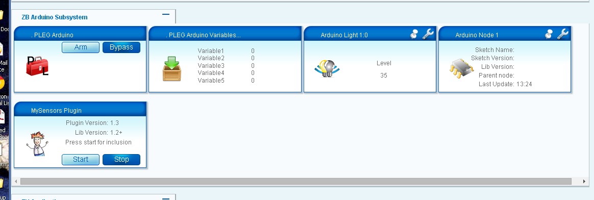
                        Well, i'm pleased to say that I got my Serial Gateway and first Sensor up. After all the problems with the "scrambled wiring" version I used Ross Kinard's PCB from OSHPark and it came up the first time. It located and included the Light Sensor immediately although it doesn't seem to have picked up all the config data (Photo attached)ScreenHunter_119 May. 11 13.27.jpg.

                        But after the previous frustrations this is a major victory :)

                        Thanks to everyone but especially to @Ross for his excellent PCB and @hek for your patience and assistance.

                        John

                        P 1 Reply Last reply
                        0
                        • C clippermiami

                          Well, i'm pleased to say that I got my Serial Gateway and first Sensor up. After all the problems with the "scrambled wiring" version I used Ross Kinard's PCB from OSHPark and it came up the first time. It located and included the Light Sensor immediately although it doesn't seem to have picked up all the config data (Photo attached)ScreenHunter_119 May. 11 13.27.jpg.

                          But after the previous frustrations this is a major victory :)

                          Thanks to everyone but especially to @Ross for his excellent PCB and @hek for your patience and assistance.

                          John

                          P Offline
                          P Offline
                          petewill
                          Admin
                          wrote on last edited by
                          #42

                          @clippermiami said:

                          ...although it doesn't seem to have picked up all the config data (Photo attached)!

                          John,

                          This is happening to me too when I first include the sensor. I just have to power cycle the sensor (light sensor in your case) and then the info appears.

                          Hope that will work for you too.

                          Pete

                          My "How To" home automation video channel: https://www.youtube.com/channel/UCq_Evyh5PQALx4m4CQuxqkA

                          C 1 Reply Last reply
                          0
                          • P petewill

                            @clippermiami said:

                            ...although it doesn't seem to have picked up all the config data (Photo attached)!

                            John,

                            This is happening to me too when I first include the sensor. I just have to power cycle the sensor (light sensor in your case) and then the info appears.

                            Hope that will work for you too.

                            Pete

                            C Offline
                            C Offline
                            clippermiami
                            Hero Member
                            wrote on last edited by
                            #43

                            @petewill That got it, thanks

                            1 Reply Last reply
                            0

                            Hello! It looks like you're interested in this conversation, but you don't have an account yet.

                            Getting fed up of having to scroll through the same posts each visit? When you register for an account, you'll always come back to exactly where you were before, and choose to be notified of new replies (either via email, or push notification). You'll also be able to save bookmarks and upvote posts to show your appreciation to other community members.

                            With your input, this post could be even better 💗

                            Register Login
                            Reply
                            • Reply as topic
                            Log in to reply
                            • Oldest to Newest
                            • Newest to Oldest
                            • Most Votes


                            28

                            Online

                            12.0k

                            Users

                            11.2k

                            Topics

                            113.4k

                            Posts


                            Copyright 2025 TBD   |   Forum Guidelines   |   Privacy Policy   |   Terms of Service
                            • Login

                            • Don't have an account? Register

                            • Login or register to search.
                            • First post
                              Last post
                            0
                            • MySensors
                            • OpenHardware.io
                            • Categories
                            • Recent
                            • Tags
                            • Popular