STM32?
-
HI @freynder ,
I just realize that when you speak about SERIAL_USB you really speak about.....Serial through USB connector :grinning: .
I believe you speak about Virtual Com Port through USB in ST-LINK.So I had change R10 on my blue pill and install maple driver.
Now I have a Maple Serial COM mounted when I connect my blue pill with the USB connector :grinning: .And......................TADA.................It is working. I had output on my terminal.
Thanks again:+1:
-
Hi @ooznerol,
Glad serial output is working now. Unfortunately I have no experience with serial gateway either, sorry.
-
In general: isolating the problem and then tracing through the code. I understand you already isolated the problem to the combination of serial gateway and RFM69. First make sure this actually the case by uploading a sketch again you knew was working before with RFM69 (to eliminate any hardware / wiring issues that may have happened between your tests). If you can confirm that, you can start by looking at the code and find what is specific for the combination of these specific directives.
-
Instead facing through the code , I think about compile with a debugger (like IAR ou Keil for example). Do you think it is possible?
@ooznerol No experience with those I'm afraid. From my notes I see I did experiment with using GDB in combination with a Black Magic Probe (BMP) to debug the blue pill. You can probably convert your SWD adapter to a BMP device:
https://madnessinthedarkness.transsys.com/blog:2017:0122_black_magic_probe_bmp_on_st-link_v2_clones
https://github.com/blacksphere/blackmagic/wiki -
@ooznerol No experience with those I'm afraid. From my notes I see I did experiment with using GDB in combination with a Black Magic Probe (BMP) to debug the blue pill. You can probably convert your SWD adapter to a BMP device:
https://madnessinthedarkness.transsys.com/blog:2017:0122_black_magic_probe_bmp_on_st-link_v2_clones
https://github.com/blacksphere/blackmagic/wikiHi all, it's me again.
So finally Gateway is working fine. The problem was that the driver (specially on windows) seems little bit unstable (I must open the serial just after strating and close it after I finish my test).
So now I am playing with consumption.
I take the low power implementation from freynder and reach 860uA. This implemenation used STOP mode. If I change this to STANDBY mode I reach 4.1uA. But in this case when I wake up, the CPU react as it has been reseted and relaunch all mysensors init and presenation etc etc . So the trick will be to check the wake up reason, and in case of wake up from standby not relaunch mysensors init. Do you think it is possible inside mysensors architecture?
Thanks
-
Hi all, it's me again.
So finally Gateway is working fine. The problem was that the driver (specially on windows) seems little bit unstable (I must open the serial just after strating and close it after I finish my test).
So now I am playing with consumption.
I take the low power implementation from freynder and reach 860uA. This implemenation used STOP mode. If I change this to STANDBY mode I reach 4.1uA. But in this case when I wake up, the CPU react as it has been reseted and relaunch all mysensors init and presenation etc etc . So the trick will be to check the wake up reason, and in case of wake up from standby not relaunch mysensors init. Do you think it is possible inside mysensors architecture?
Thanks
@ooznerol I suppose you intend to run on battery? I desoldered the power led and voltage regulator on mine to reach 100uA (if readings were correct) using STOP mode. It ran on 2 AAA batteries for several months.
I'm unsure about using the STANDBY mode. Since RAM and registers contents are lost and pins are high impedance, full reinitialization seems necessary. Do you want to prevent the presentation communication specifically from happening? You can control that from your sketch directly in the presentation function I suppose...
-
@ooznerol I suppose you intend to run on battery? I desoldered the power led and voltage regulator on mine to reach 100uA (if readings were correct) using STOP mode. It ran on 2 AAA batteries for several months.
I'm unsure about using the STANDBY mode. Since RAM and registers contents are lost and pins are high impedance, full reinitialization seems necessary. Do you want to prevent the presentation communication specifically from happening? You can control that from your sketch directly in the presentation function I suppose...
@freynder Yes I have of course remove unless hardware. ( i can't reach 3.3uA with it). In STOP mode, we are suppose to reach around 20-30uA (from datasheet). I will try yo investigate
I can of course handle reset cause into presentation, but I don't know if other init are done inside mysensors architecture.
For STANDBY mode , we can save usefull data for mysensors into backup register. I had done something similar in the past but not in stm32duino environnement. -
@freynder Yes I have of course remove unless hardware. ( i can't reach 3.3uA with it). In STOP mode, we are suppose to reach around 20-30uA (from datasheet). I will try yo investigate
I can of course handle reset cause into presentation, but I don't know if other init are done inside mysensors architecture.
For STANDBY mode , we can save usefull data for mysensors into backup register. I had done something similar in the past but not in stm32duino environnement.I can of course handle reset cause into presentation, but I don't know if other init are done inside mysensors architecture.
For STANDBY mode , we can save usefull data for mysensors into backup register. I had done something similar in the past but not in stm32duino environnement.Yes, before the presentation MySensors will initialize radio, check radio link/parent etc
There's no easy way to avoid it at the moment, but I think it should be a feature request, as we have the same situation with chips like NRF51/NRF52 which are also ARM based, if you want really low power consumption you need to go through a reset and MySensors initialization phase makes the wake up slow and power hungry. -
Just got a blue-pill, RFM69 node working. It was a bit of a learning curve moving from Atmega.
- Cheap J-Link: Never got it working. Cheap ST-Link: Worked
- Arduino (and VisualMicro) uploaded blink sketch with ST-Link: no problems
- Uploaded the USB bootloader using the ST-Link: no problems
- Took a while to figure out I didn't have the dfu driver loaded (Windows 10), but after that no problems using the usb
- MySensors security personalizer: no problems.
- Mock MySensors node: no problems. Talked to my gateway. Uses RFM69 encryption.
Seems like this is the Nano of the future, but without needing to level shift for 3.3V. I'm looking forward to making some real blue pill nodes and gateways.
-
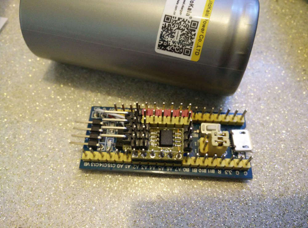
So.. I accidentally bought something from Aliexpress that I thought was a cheap Arduino Nano.
But it's not.
It's an STM32F103C8T6. It has an arm chip.
Is it useable with MySensors? Does it emulate an Arduino Nano? Of so, it looks like it has more memory, so could that be useful? It's cheaper too, and it has lots of 3v lines.
I just found this page where someone talks about their adventures with this board. Hmm...
-
stm32 sensor is unable to connect to gateway:
After further testing, this seems to work now. I'm not exactly sure why unfortunately. I'm now using the new RFM69 library. I noticed that communication seems to fail after uploading the sketch over stlink, even when clicking the reset button. When disconnecting/reconnecting the usb power all works well. Maybe that was the issue previously as well.
Just following up on this as I finally found out why this is happening. I was using encryption and using serial upload (using stm32flash), the simulated eeprom would get overwritten by the flash erase. Not sure if this happens for dfu or stlink as well. Uploading using the black magic probe (which uses dbg) does not have this problem. I hope this may help someone struggling with the same issue.
Edit: not sure about dfu or stlink.
-
@nagelc Yes I did. My bootloader - https://github.com/mysensors-rus/STM32_Mysensors_bootloader. My modified MySensors library - https://github.com/mysensors-rus/MySensors. Short description in Russian - https://mysensors-rus.github.io/STM32-OTA-MySensors
-
@nagelc Yes I did. My bootloader - https://github.com/mysensors-rus/STM32_Mysensors_bootloader. My modified MySensors library - https://github.com/mysensors-rus/MySensors. Short description in Russian - https://mysensors-rus.github.io/STM32-OTA-MySensors
-
@dab0g Wow! I did not expect anyone to answer. This is really great. I have a remote control lamp and a thermostat that use the STM32 and it would great to be able to program them OTA. I'll check it out.