Skip to content
  • MySensors
  • OpenHardware.io
  • Categories
  • Recent
  • Tags
  • Popular
Skins
  • Light
  • Brite
  • Cerulean
  • Cosmo
  • Flatly
  • Journal
  • Litera
  • Lumen
  • Lux
  • Materia
  • Minty
  • Morph
  • Pulse
  • Sandstone
  • Simplex
  • Sketchy
  • Spacelab
  • United
  • Yeti
  • Zephyr
  • Dark
  • Cyborg
  • Darkly
  • Quartz
  • Slate
  • Solar
  • Superhero
  • Vapor

  • Default (No Skin)
  • No Skin
Collapse
Brand Logo
  1. Home
  2. OpenHardware.io
  3. 💬 Easy/Newbie PCB (RFM69 HW/W edition) for MySensors

💬 Easy/Newbie PCB (RFM69 HW/W edition) for MySensors

Scheduled Pinned Locked Moved OpenHardware.io
mysensoreasynewbiepcbmysx
106 Posts 20 Posters 36.5k Views 19 Watching
  • Oldest to Newest
  • Newest to Oldest
  • Most Votes
Reply
  • Reply as topic
Log in to reply
This topic has been deleted. Only users with topic management privileges can see it.
  • openhardware.ioO Offline
    openhardware.ioO Offline
    openhardware.io
    wrote on last edited by openhardware.io
    #1

    https://www.openhardware.io/view/389/EasyNewbie-PCB-RFM69-HWW-edition-for-MySensors

    1 Reply Last reply
    2
    • gohanG Offline
      gohanG Offline
      gohan
      Mod
      wrote on last edited by
      #2

      :thumbsup: Finally! :D

      1 Reply Last reply
      1
      • martinhjelmareM Offline
        martinhjelmareM Offline
        martinhjelmare
        Plugin Developer
        wrote on last edited by
        #3

        How's the compatability 5 V arduino and RFM69 achieved? As I understand the RFM69 inputs are not 5 V tolerable.

        1 Reply Last reply
        0
        • gohanG Offline
          gohanG Offline
          gohan
          Mod
          wrote on last edited by
          #4

          You need to use 3,3v mini pro, this pcb is more for battery powered nodes

          1 Reply Last reply
          0
          • sundberg84S Offline
            sundberg84S Offline
            sundberg84
            Hardware Contributor
            wrote on last edited by
            #5

            Correct - 3.3v only - im redesigning the PCB for this.

            1 Reply Last reply
            0
            • martinhjelmareM Offline
              martinhjelmareM Offline
              martinhjelmare
              Plugin Developer
              wrote on last edited by
              #6

              Ok, so it was just a copy-paste leftover in the feature description from the nrf version.

              sundberg84S 1 Reply Last reply
              0
              • martinhjelmareM martinhjelmare

                Ok, so it was just a copy-paste leftover in the feature description from the nrf version.

                sundberg84S Offline
                sundberg84S Offline
                sundberg84
                Hardware Contributor
                wrote on last edited by sundberg84
                #7

                @martinhjelmare - It wasnt meant to make the project visible but I did unfortunately. I will correct as soon as possible
                I dont think its going to be that newbie friendly with a level converter for 5v so Im going to propose a 3.3v Pro mini only. Then I might add a voltage regulator with 5 and 3.3v in.

                1 Reply Last reply
                1
                • sundberg84S Offline
                  sundberg84S Offline
                  sundberg84
                  Hardware Contributor
                  wrote on last edited by sundberg84
                  #8

                  Well, since I posted the thread without it was finished (not usually my way of working) I can keep you updated on the work i guess... get input on the way.

                  New schematics made... not final! Not implemented any booster yet.
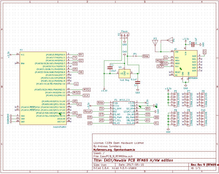
                  0_1494430456876_Sch_beta.JPG

                  1 Reply Last reply
                  0
                  • sundberg84S Offline
                    sundberg84S Offline
                    sundberg84
                    Hardware Contributor
                    wrote on last edited by sundberg84
                    #9

                    @gohan - looking better on that SMA connector...
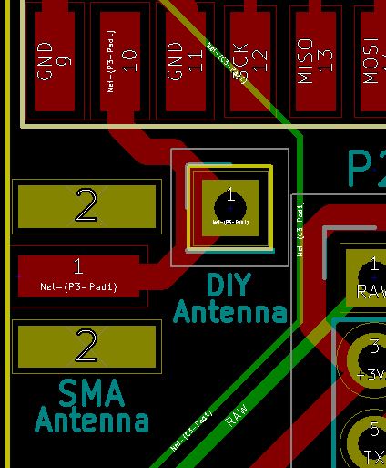
                    0_1494441088218_Ant.JPG

                    Anyone knows if its possible to have a SMA and Hole for DIY antenna on the same PCB like this?

                    Edit:
                    Well, so far tonight... a couple of hours work and im happy :) some small stuff to fix before production.
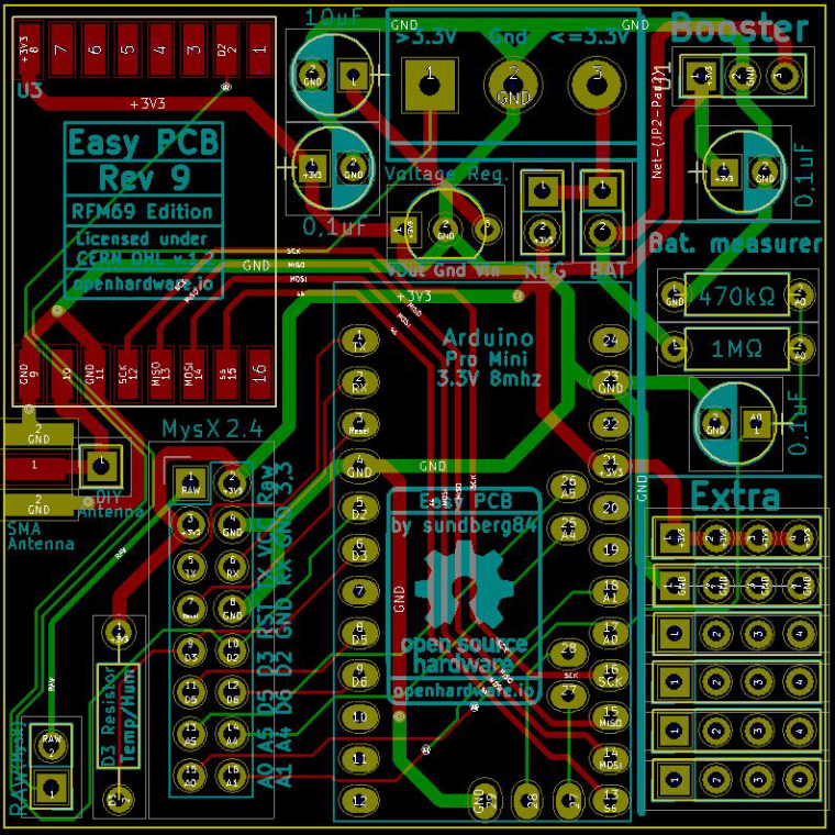
                    0_1494445821526_SoFar.JPG

                    J 1 Reply Last reply
                    3
                    • fisherF Offline
                      fisherF Offline
                      fisher
                      wrote on last edited by
                      #10

                      Looking forward to buy this board. Thanks for including SMA connector. Now it's complete board for me :-)

                      1 Reply Last reply
                      1
                      • sundberg84S Offline
                        sundberg84S Offline
                        sundberg84
                        Hardware Contributor
                        wrote on last edited by sundberg84
                        #11

                        OK - beta release.

                        I have updated the description, bom, gerber files and kicad files on openhardware.io.
                        I have placed an order for fast delivery on pcbway.com but it will take some time before my RFM69 radios reach me from china-land. So I won't be able to test it for some time.

                        IF you are curoius (and willing to debug and cut / resolder if there are errors) feel free to download the gerbers and place an order. I cant promise its 100% (or work as intended) and because of that I wont add them for sale on openhardware.io yet.
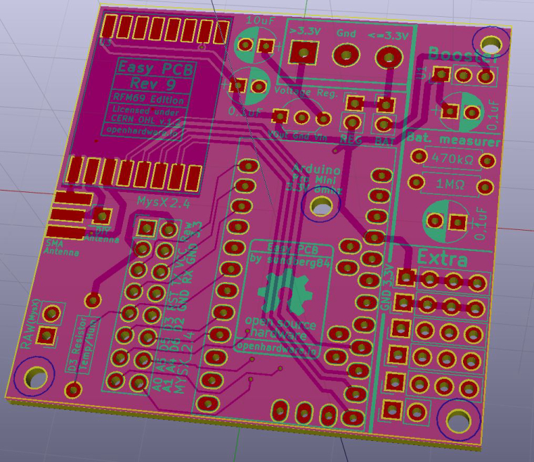
                        0_1494528446674_3D.JPG

                        1 Reply Last reply
                        1
                        • sundberg84S sundberg84

                          @gohan - looking better on that SMA connector...
                          0_1494441088218_Ant.JPG

                          Anyone knows if its possible to have a SMA and Hole for DIY antenna on the same PCB like this?

                          Edit:
                          Well, so far tonight... a couple of hours work and im happy :) some small stuff to fix before production.
                          0_1494445821526_SoFar.JPG

                          J Offline
                          J Offline
                          jlaraujo
                          wrote on last edited by
                          #12

                          @sundberg84 I did this in my take of a SMA with a wire Antenna option:
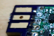
                          0_1494632694334_upload-ce399877-38ed-4251-924d-a293c9df13fb , you can see more details here https://www.openhardware.io/view/388/RFM69HW-Arduino-Mini-Pro-Shield.
                          Haven't tried with the wire antenna trough.

                          Domoticz, mysensors 2.3.1, RFM69 and RF24 sensors

                          sundberg84S 1 Reply Last reply
                          2
                          • gohanG Offline
                            gohanG Offline
                            gohan
                            Mod
                            wrote on last edited by
                            #13

                            Actually it seems a good solution to have the hole on the sma pad

                            1 Reply Last reply
                            1
                            • J jlaraujo

                              @sundberg84 I did this in my take of a SMA with a wire Antenna option:
                              0_1494632694334_upload-ce399877-38ed-4251-924d-a293c9df13fb , you can see more details here https://www.openhardware.io/view/388/RFM69HW-Arduino-Mini-Pro-Shield.
                              Haven't tried with the wire antenna trough.

                              sundberg84S Offline
                              sundberg84S Offline
                              sundberg84
                              Hardware Contributor
                              wrote on last edited by
                              #14

                              @jlaraujo , @gohan - I does look really good and effective!
                              Would be great if you could test it! At the moment I have placed my order so I cant change it for this run, but out of experience there will be other stuff I want to change.

                              Thank you for input! I greatly appreciate it!

                              1 Reply Last reply
                              0
                              • sundberg84S Offline
                                sundberg84S Offline
                                sundberg84
                                Hardware Contributor
                                wrote on last edited by sundberg84
                                #15
                                This post is deleted!
                                1 Reply Last reply
                                0
                                • sundberg84S Offline
                                  sundberg84S Offline
                                  sundberg84
                                  Hardware Contributor
                                  wrote on last edited by
                                  #16

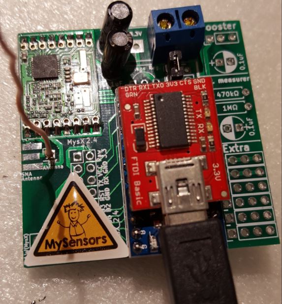
                                  So, this temporary GW is now connected to Domoticz and running at 34800 baud rate (had some problems to figure this out...) I have one (fake) node connected but still have some range issues to sort out. Most likley because of the DIY antenna...
                                  0_1497989310348_1.JPG

                                  1 Reply Last reply
                                  1
                                  • sundberg84S Offline
                                    sundberg84S Offline
                                    sundberg84
                                    Hardware Contributor
                                    wrote on last edited by
                                    #17

                                    I now have a gw and node working together on 3.3v and 433mhz (not HW version). I would say its quite safe to order the PCB if someone wants to try it out.

                                    Note to myself and others... the RFM69 is really sensitive to high power. I fried one because I tried it on a Nano which i think is using 5v on its gpio. I was just thinking... hmm 3.3v - nano got one of those!

                                    gohanG 1 Reply Last reply
                                    0
                                    • sundberg84S Offline
                                      sundberg84S Offline
                                      sundberg84
                                      Hardware Contributor
                                      wrote on last edited by sundberg84
                                      #18

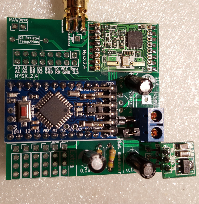
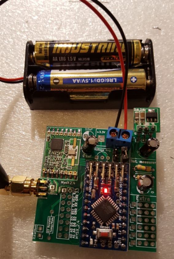
                                      And now I also have a batterynode working... Power consumtion will come later... it works atleast :)
                                      Someone that can guess what kind of power consumtion this setup would be (removing LED / regulator)?
                                      0_1498418704326_battery.jpg0_1498419175750_1.JPG

                                      1 Reply Last reply
                                      0
                                      • sundberg84S sundberg84

                                        I now have a gw and node working together on 3.3v and 433mhz (not HW version). I would say its quite safe to order the PCB if someone wants to try it out.

                                        Note to myself and others... the RFM69 is really sensitive to high power. I fried one because I tried it on a Nano which i think is using 5v on its gpio. I was just thinking... hmm 3.3v - nano got one of those!

                                        gohanG Offline
                                        gohanG Offline
                                        gohan
                                        Mod
                                        wrote on last edited by
                                        #19

                                        @sundberg84 said in 💬 Easy/Newbie PCB (RFM69 HW/W edition) for MySensors:

                                        I now have a gw and node working together on 3.3v and 433mhz (not HW version). I would say its quite safe to order the PCB if someone wants to try it out.

                                        Note to myself and others... the RFM69 is really sensitive to high power. I fried one because I tried it on a Nano which i think is using 5v on its gpio. I was just thinking... hmm 3.3v - nano got one of those!

                                        It's in datasheet that it is not 5v tolerant and absolute max voltage it's like 3.6v

                                        sundberg84S 1 Reply Last reply
                                        1
                                        • gohanG gohan

                                          @sundberg84 said in 💬 Easy/Newbie PCB (RFM69 HW/W edition) for MySensors:

                                          I now have a gw and node working together on 3.3v and 433mhz (not HW version). I would say its quite safe to order the PCB if someone wants to try it out.

                                          Note to myself and others... the RFM69 is really sensitive to high power. I fried one because I tried it on a Nano which i think is using 5v on its gpio. I was just thinking... hmm 3.3v - nano got one of those!

                                          It's in datasheet that it is not 5v tolerant and absolute max voltage it's like 3.6v

                                          sundberg84S Offline
                                          sundberg84S Offline
                                          sundberg84
                                          Hardware Contributor
                                          wrote on last edited by
                                          #20

                                          @gohan - I was fooled by that the Nano got a 3.3v output... stupid.

                                          1 Reply Last reply
                                          0
                                          Reply
                                          • Reply as topic
                                          Log in to reply
                                          • Oldest to Newest
                                          • Newest to Oldest
                                          • Most Votes


                                          9

                                          Online

                                          11.7k

                                          Users

                                          11.2k

                                          Topics

                                          113.0k

                                          Posts


                                          Copyright 2019 TBD   |   Forum Guidelines   |   Privacy Policy   |   Terms of Service
                                          • Login

                                          • Don't have an account? Register

                                          • Login or register to search.
                                          • First post
                                            Last post
                                          0
                                          • MySensors
                                          • OpenHardware.io
                                          • Categories
                                          • Recent
                                          • Tags
                                          • Popular