nRF5 action!
-
Great that it works.
But I'm not so convinced about the usefulness of this method, anyways.
I know that a lot of receivers use simple RSSI measurement to implement a low power listening mode, but when you are in a noisy environment, the system will wake up quite often, draining the battery fast. And unless you live in a very remote area, 2.4 GHz IS a noisy environment.@Uhrheber said in nRF5 Bluetooth action!:
Great that it works.
But I'm not so convinced about the usefulness of this method, anyways.
I know that a lot of receivers use simple RSSI measurement to implement a low power listening mode, but when you are in a noisy environment, the system will wake up quite often, draining the battery fast. And unless you live in a very remote area, 2.4 GHz IS a noisy environment.And your better alternative is....?
-
@d00616 said in nRF5 Bluetooth action!:
It looks like you are implementing a new radio protocol and you are coming forward.
Yes, I'm presently focused on trying to reduce the amount of energy consumed by probably the hardest case of all: a battery/solar/supercap receiver that needs to be both highly responsive (within 100ms) and listening 24/7 without running out of juice. Of course, one can always throw bigger batteries or bigger solar panels at the problem, but I'm first trying to be as ultra efficient as possible so that won't be necessary. The benefit will be smaller size, not to mention lower cost.
I am posting my findings as I go because there is precious little in the way of working examples, so I may yet still be of help to others in that way. From the view count, it does seem that people are reading this thread, even if not many are posting.
@NeverDie said in nRF5 Bluetooth action!:
From the view count, it does seem that people are reading this thread, even if not many are posting.
I'm following your work with interest of course ;) On my side i'm pretty busy on other stuff (rpi and my HA) so i'm missing time for try..I'll be back soon on this!
@NeverDie said in nRF5 Bluetooth action!:
t what to do next. However, I don't see
I thought too, about implementing this kind of listenmode for rfm69 in my HA. What i don't like so much, is I think i would need a dedicated node for the scheduling and it complicates a bit thing. I'm not fond of using gw resources for the wakeup broadcast.
I think, maybe I'm wrong, that, ideally, the best would be "time slots" so everything would be in sync, no flooding broadcast, lost msg, collisions etc.. but that implies some work regarding the lib, and some hw issues (with simple 8bits without precise rtc).Keep the good work!
-
@Uhrheber said in nRF5 Bluetooth action!:
Great that it works.
But I'm not so convinced about the usefulness of this method, anyways.
I know that a lot of receivers use simple RSSI measurement to implement a low power listening mode, but when you are in a noisy environment, the system will wake up quite often, draining the battery fast. And unless you live in a very remote area, 2.4 GHz IS a noisy environment.And your better alternative is....?
@NeverDie None, unfortunately. The manufacturer would have to take care of that, by implementing a low power mode in the receiver (maybe with reduced sensitivity), and an additional low power wakeup pattern detector.
There are transceiver that can do that, but the nRF52 can't.Some of the simple 433MHz OOK receivers have a low current consumption, but they're pretty insensitive, high bandwidth and low speed, so of not much use except switching some battery powered lamp, or such.
Some time ago I searched for a transceiver with low current receive mode, to use it in a battery powered node, that could be woken up by rf, but found nothing.
All of the standard data transceivers are pretty power hungry. -
Interesting study regarding nrf51/nrf52 power consumption:
-
Interesting study regarding nrf51/nrf52 power consumption:
@Toyman Indeed:
Nonetheless, larger AA or AAA type
batteries are still required to reliably achieve operation times
of a year or longer with high advertising rates.As I thought.
And for more advanced modulations, like LoRa, the power consumption is even higher. -
@NeverDie None, unfortunately. The manufacturer would have to take care of that, by implementing a low power mode in the receiver (maybe with reduced sensitivity), and an additional low power wakeup pattern detector.
There are transceiver that can do that, but the nRF52 can't.Some of the simple 433MHz OOK receivers have a low current consumption, but they're pretty insensitive, high bandwidth and low speed, so of not much use except switching some battery powered lamp, or such.
Some time ago I searched for a transceiver with low current receive mode, to use it in a battery powered node, that could be woken up by rf, but found nothing.
All of the standard data transceivers are pretty power hungry.@Uhrheber said in nRF5 Bluetooth action!:
Some time ago I searched for a transceiver with low current receive mode, to use it in a battery powered node, that could be woken up by rf, but found nothing.
TI and Silicon Labs have both had chips with "wake on radio". e.g. http://www.ti.com/lit/an/swra126b/swra126b.pdf
The Rx current consumption of the nRF52832 seems pretty good, especially with DCDC regulator enabled. Seems to me that the RSSI detection implemented in PPI is a big improvement, even in noisy environments for the following reasons: the RSSI measurement takes only 0.25us, according to the DS. That's very little overhead. If the Radio gets switched on due to a false positive on the RSSI, well, it would have had to be switched on anyway even without the RSSI. I don't see the downside to this. The more noisy the environment, the less effective the technique is, but I don't see that you'd ever really be worse off for using it.
-
@d00616
If I'm usingsleep(1000000000);to sleep the CPU while keeping the PPI active, is there a way for the PPI to subsequently wake the CPU so that the CPU can resume where it left off? I'm not seeing any TASKS which look suitable for doing that. Or do I need an altogether different configuration for sleeping the CPU?
Back on August 5, @RMTUCKER had suggested using:sleep(digitalPinToInterrupt(10), FALLING,0);If I were to go that route, I could probably have the PPI toggle PIN 10 to do a wake-up, but I found that, for whatever reason, that method of sleeping had a much higher current draw.[Edit: scratch that. I just tried "sleep(digitalPinToInterrupt(10), FALLING,0);", and it appears to turn-off PPI. Oddly enough, it appears to leave the RTC running, which is actually just fine by me. However, I need the PPI running too. ]
-
@Toyman Indeed:
Nonetheless, larger AA or AAA type
batteries are still required to reliably achieve operation times
of a year or longer with high advertising rates.As I thought.
And for more advanced modulations, like LoRa, the power consumption is even higher. -
It turns out the cost in current consumption of waking the MCU merely to check the RSSISAMPLE result is relatively high:
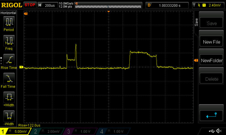
The first hump is the current drawn by the PPI and RSSI sample. The second hump is the current drawn by MCU.
Measurement Scale: 1mv=1ma.
Anyhow, the RSSISAMPLE measurement, as reported by the MCU, is abnormally high. It may be that I need to put the radio into RX state, instead of just RXIDLE, before taking the RSSI measurement.
-
@NeverDie said in nRF5 Bluetooth action!:
Is there any example code which illustrates the use of interrupts on the nRF52832?
Yes. In a sketch, you have to put the interrupt routine into one line. You can define the interrupt only once. If you want to use the radio ISR, you can't enable the radio in MySensors.
https://github.com/sandeepmistry/arduino-nRF5/issues/52
https://github.com/mysensors/MySensors/blob/development/drivers/NRF5/Radio_ESB.cpp#L500
This post is deleted! -
@d00616
If I'm usingsleep(1000000000);to sleep the CPU while keeping the PPI active, is there a way for the PPI to subsequently wake the CPU so that the CPU can resume where it left off? I'm not seeing any TASKS which look suitable for doing that. Or do I need an altogether different configuration for sleeping the CPU?
Back on August 5, @RMTUCKER had suggested using:sleep(digitalPinToInterrupt(10), FALLING,0);If I were to go that route, I could probably have the PPI toggle PIN 10 to do a wake-up, but I found that, for whatever reason, that method of sleeping had a much higher current draw.[Edit: scratch that. I just tried "sleep(digitalPinToInterrupt(10), FALLING,0);", and it appears to turn-off PPI. Oddly enough, it appears to leave the RTC running, which is actually just fine by me. However, I need the PPI running too. ]
@NeverDie said in nRF5 Bluetooth action!:
to sleep the CPU while keeping the PPI active, is there a way for the PPI to subsequently wake the CPU so that the CPU can resume where it left off? I'm not seeing any TASKS which look suitable for doing that. Or do I need an altogether different configuration for sleeping the CPU?
The PPI cannot wake up the CPU. You can try to trigger events to a timer which resumes the CPU.
@NeverDie said in nRF5 Bluetooth action!:
Are there special reserved names to always use for the IRQ handlers? e.g. GPIOTE_IRQHandler(void), and so on?
The names are defined there:
-
@NeverDie said in nRF5 Bluetooth action!:
Is there any example code which illustrates the use of interrupts on the nRF52832?
Yes. In a sketch, you have to put the interrupt routine into one line. You can define the interrupt only once. If you want to use the radio ISR, you can't enable the radio in MySensors.
https://github.com/sandeepmistry/arduino-nRF5/issues/52
https://github.com/mysensors/MySensors/blob/development/drivers/NRF5/Radio_ESB.cpp#L500
@d00616 said in nRF5 Bluetooth action!:
Yes. In a sketch, you have to put the interrupt routine into one line. You can define the interrupt only once. If you want to use the radio ISR, you can't enable the radio in MySensors.
Does the current development software support the use of at most one ISR in total at any one time?
-
@NeverDie said in nRF5 Bluetooth action!:
to sleep the CPU while keeping the PPI active, is there a way for the PPI to subsequently wake the CPU so that the CPU can resume where it left off? I'm not seeing any TASKS which look suitable for doing that. Or do I need an altogether different configuration for sleeping the CPU?
The PPI cannot wake up the CPU. You can try to trigger events to a timer which resumes the CPU.
@NeverDie said in nRF5 Bluetooth action!:
Are there special reserved names to always use for the IRQ handlers? e.g. GPIOTE_IRQHandler(void), and so on?
The names are defined there:
I changed your example to use sleep(...) instead of delay(...) in the main loop, but what then becomes obvious is that the interrupts don't wake up the MCU. Well, in a sense they do, because the ISR is executed, but the MCU doesn't remain awake like it would on an Arduino. So, how does one escape the sleep mode after it has begun without waiting for it to simply time out?
// This code is public domain

#include <nrf.h>
#include <MySensors.h>

//#define RTC NRF_RTC0
//#define RTC_IRQ RTC0_IRQn

int interrupt = 0;

void setup() {
  // put your setup code here, to run once:
  Serial.begin(250000);
  Serial.println("Start");

  // Configure RTC
  NRF_RTC0->TASKS_STOP = 1;
  NRF_RTC0->PRESCALER = 31; //1024Hz frequency
  NRF_RTC0->CC[0] = NRF_RTC0->COUNTER + (3 * 1024);
  NRF_RTC0->EVTENSET = RTC_EVTENSET_COMPARE0_Msk;
  NRF_RTC0->INTENSET = RTC_INTENSET_COMPARE0_Msk;
  NRF_RTC0->TASKS_START = 1;
  NRF_RTC0->EVENTS_COMPARE[0] = 0;

  // Enable interrupt
  NVIC_SetPriority(RTC0_IRQn, 15);
  NVIC_ClearPendingIRQ(RTC0_IRQn);
  NVIC_EnableIRQ(RTC0_IRQn);
  Serial.println();
  Serial.println();
  Serial.println("Starting...");
}

void loop() {
  Serial.print(millis());
  Serial.print(" ");
  Serial.print(NRF_RTC0->COUNTER);
  Serial.print(" ");
  Serial.println(interrupt);
  sleep(10000);
}

/**
 * Reset events and read back on nRF52
 * http://infocenter.nordicsemi.com/pdf/nRF52_Series_Migration_v1.0.pdf
 */
#if __CORTEX_M == 0x04
#define NRF5_RESET_EVENT(event)                                                 \
        event = 0;                                                                   \
        (void)event
#else
#define NRF5_RESET_EVENT(event) event = 0
#endif

// This must be in one line
extern "C" { void RTC0_IRQHandler(void) { NRF5_RESET_EVENT(NRF_RTC0->EVENTS_COMPARE[0]); interrupt++; NRF_RTC0->TASKS_CLEAR = 1; }}
I guess maybe the answer is to clear the SLEEPONEXIT bit in the System Control Register (SCR) before exiting the ISR? The SCR is described on page 4-19 of: http://infocenter.arm.com/help/topic/com.arm.doc.dui0553a/DUI0553A_cortex_m4_dgug.pdf
At the moment, though, I'm not even sure how to access that register, as so far I've only seen the API for the nRF52832 generally, not the code interface for the ARM Cortex M4 per se that's inside it. -
@NeverDie
I am a little lost with this,I am using sleep and wake from ext int on the nrf51 and it has been working every second for the last 2 weeks.
What kind of int are you trying to implement?@rmtucker said in nRF5 Bluetooth action!:
@NeverDie
I am a little lost with this,I am using sleep and wake from ext int on the nrf51 and it has been working every second for the last 2 weeks.
What kind of int are you trying to implement?This is for the case where the PPI is doing things (like, for example, getting the radio to periodically listen for incoming packets) all while the CPU is sleeping. If, for instance, a packet is received in that mode, the CPU needs to be awoken to process it.
So, this is different than the easier case (which I already have working) of sleeping the CPU, then it wakes up every, say, 100ms, and then the CPU controls the radio to listen for packets and then takes action if one is received. Instead, this is a case where the PPI is controlling the radio while the CPU sleeps.
The PPI has a lot of power saving potential, so we're figuring out how best to exploit that potential.
Also, the more general topic of how to use interrupts and ISR's on the nRF52832 (such as how many different ones can be active at once, as supported by the current development code) needs to be addressed, independent of the regular sleep(..) function.
-
@rmtucker said in nRF5 Bluetooth action!:
@NeverDie
All we need right now is a controller that covers the majority of home use.
Tried domoticz for 2 years and it covers energy use and cost really well but then is limited to saving data every 5mins and no mixed/multisensor graphs to any extent so useless for my current needs.
Tried myHouse for 6 months and it,s graphing was great but the display of binary sensors were not in real time and it does not do energy use at all.
I can not find a controller that seems to cover average needs for automation/energy/and realtime feedback.
I know it's a little off topic but it is a big problem when you can build the range of mysensors using the nrf5 but then not be able to get the feedback and energy/cost stuff on the screen.
Maybe i am just disgruntled that the controllers do not seem to keep up with the electronics very well.Yes, agreed, but please let's not go into that here, because it would seriously throw us off topic. You might try: https://forum.mysensors.org/topic/7178/are-folks-here-happy-with-domoticz/63 which has some useful suggestions, especially regarding Node Red and MQTT.
-
I changed your example to use sleep(...) instead of delay(...) in the main loop, but what then becomes obvious is that the interrupts don't wake up the MCU. Well, in a sense they do, because the ISR is executed, but the MCU doesn't remain awake like it would on an Arduino. So, how does one escape the sleep mode after it has begun without waiting for it to simply time out?
// This code is public domain

#include <nrf.h>
#include <MySensors.h>

//#define RTC NRF_RTC0
//#define RTC_IRQ RTC0_IRQn

int interrupt = 0;

void setup() {
  // put your setup code here, to run once:
  Serial.begin(250000);
  Serial.println("Start");

  // Configure RTC
  NRF_RTC0->TASKS_STOP = 1;
  NRF_RTC0->PRESCALER = 31; //1024Hz frequency
  NRF_RTC0->CC[0] = NRF_RTC0->COUNTER + (3 * 1024);
  NRF_RTC0->EVTENSET = RTC_EVTENSET_COMPARE0_Msk;
  NRF_RTC0->INTENSET = RTC_INTENSET_COMPARE0_Msk;
  NRF_RTC0->TASKS_START = 1;
  NRF_RTC0->EVENTS_COMPARE[0] = 0;

  // Enable interrupt
  NVIC_SetPriority(RTC0_IRQn, 15);
  NVIC_ClearPendingIRQ(RTC0_IRQn);
  NVIC_EnableIRQ(RTC0_IRQn);
  Serial.println();
  Serial.println();
  Serial.println("Starting...");
}

void loop() {
  Serial.print(millis());
  Serial.print(" ");
  Serial.print(NRF_RTC0->COUNTER);
  Serial.print(" ");
  Serial.println(interrupt);
  sleep(10000);
}

/**
 * Reset events and read back on nRF52
 * http://infocenter.nordicsemi.com/pdf/nRF52_Series_Migration_v1.0.pdf
 */
#if __CORTEX_M == 0x04
#define NRF5_RESET_EVENT(event)                                                 \
        event = 0;                                                                   \
        (void)event
#else
#define NRF5_RESET_EVENT(event) event = 0
#endif

// This must be in one line
extern "C" { void RTC0_IRQHandler(void) { NRF5_RESET_EVENT(NRF_RTC0->EVENTS_COMPARE[0]); interrupt++; NRF_RTC0->TASKS_CLEAR = 1; }}
I guess maybe the answer is to clear the SLEEPONEXIT bit in the System Control Register (SCR) before exiting the ISR? The SCR is described on page 4-19 of: http://infocenter.arm.com/help/topic/com.arm.doc.dui0553a/DUI0553A_cortex_m4_dgug.pdf
At the moment, though, I'm not even sure how to access that register, as so far I've only seen the API for the nRF52832 generally, not the code interface for the ARM Cortex M4 per se that's inside it.@NeverDie said in nRF5 Bluetooth action!:
At the moment, though, I'm not even sure how to access that register, as so far I've only seen the API for the nRF52832 generally, not the code interface for the ARM Cortex M4 per se that's inside it.
OK, the file core_cm4.h is where the structure that contains the SCR is defined:
typedef struct
{
  __IM  uint32_t CPUID;                  /*!< Offset: 0x000 (R/ )  CPUID Base Register */
  __IOM uint32_t ICSR;                   /*!< Offset: 0x004 (R/W)  Interrupt Control and State Register */
  __IOM uint32_t VTOR;                   /*!< Offset: 0x008 (R/W)  Vector Table Offset Register */
  __IOM uint32_t AIRCR;                  /*!< Offset: 0x00C (R/W)  Application Interrupt and Reset Control Register */
  __IOM uint32_t SCR;                    /*!< Offset: 0x010 (R/W)  System Control Register */
  __IOM uint32_t CCR;                    /*!< Offset: 0x014 (R/W)  Configuration Control Register */
  __IOM uint8_t  SHP[12U];               /*!< Offset: 0x018 (R/W)  System Handlers Priority Registers (4-7, 8-11, 12-15) */
  __IOM uint32_t SHCSR;                  /*!< Offset: 0x024 (R/W)  System Handler Control and State Register */
  __IOM uint32_t CFSR;                   /*!< Offset: 0x028 (R/W)  Configurable Fault Status Register */
  __IOM uint32_t HFSR;                   /*!< Offset: 0x02C (R/W)  HardFault Status Register */
  __IOM uint32_t DFSR;                   /*!< Offset: 0x030 (R/W)  Debug Fault Status Register */
  __IOM uint32_t MMFAR;                  /*!< Offset: 0x034 (R/W)  MemManage Fault Address Register */
  __IOM uint32_t BFAR;                   /*!< Offset: 0x038 (R/W)  BusFault Address Register */
  __IOM uint32_t AFSR;                   /*!< Offset: 0x03C (R/W)  Auxiliary Fault Status Register */
  __IM  uint32_t PFR[2U];                /*!< Offset: 0x040 (R/ )  Processor Feature Register */
  __IM  uint32_t DFR;                    /*!< Offset: 0x048 (R/ )  Debug Feature Register */
  __IM  uint32_t ADR;                    /*!< Offset: 0x04C (R/ )  Auxiliary Feature Register */
  __IM  uint32_t MMFR[4U];               /*!< Offset: 0x050 (R/ )  Memory Model Feature Register */
  __IM  uint32_t ISAR[5U];               /*!< Offset: 0x060 (R/ )  Instruction Set Attributes Register */
        uint32_t RESERVED0[5U];
  __IOM uint32_t CPACR;                  /*!< Offset: 0x088 (R/W)  Coprocessor Access Control Register */
} SCB_Type;
Unfortunately, I just checked its status, and it's already cleared. So, something else is causing the MCU to go back to sleep at the end of the ISR.
The problem is that an ISR needs to be as short as possible. If something more elaborate needs to happen as a result of an interrupt, whether it be printing a bunch of debug information or something else, it should happen outside the ISR. Right now I don't see how to do that, because the MCU always immediately goes back to sleep after the ISR finishes. I suppose it must be something inside the sleep(..) routine that causes this?