multiple buttons on one analog pin arduino
-
I have a problem with programming of an arduino, I want to link 32 push-buttons on one analogic pin on the arduino that communicate radio using NRF with domoticz system on which I have 32 relay's
Can someone help me with the code?
Until now I did
/**- The MySensors Arduino library handles the wireless radio link and protocol
- between your home built sensors/actuators and HA controller of choice.
- The sensors forms a self healing radio network with optional repeaters. Each
- repeater and gateway builds a routing tables in EEPROM which keeps track of the
- network topology allowing messages to be routed to nodes.
- Created by Henrik Ekblad henrik.ekblad@mysensors.org
- Copyright (C) 2013-2015 Sensnology AB
- Full contributor list: https://github.com/mysensors/Arduino/graphs/contributors
- Documentation: http://www.mysensors.org
- Support Forum: http://forum.mysensors.org
- This program is free software; you can redistribute it and/or
- modify it under the terms of the GNU General Public License
- version 2 as published by the Free Software Foundation.
- DESCRIPTION
- Simple binary switch example
- Connect button or door/window reed switch between
- digitial I/O pin 3 (BUTTON_PIN below) and GND.
- http://www.mysensors.org/build/binary
*/
// Enable debug prints to serial monitor
#define MY_DEBUG// Enable and select radio type attached
#define MY_RADIO_NRF24
//#define MY_RADIO_RFM69#include <SPI.h>
#include <MySensors.h>
#include <Bounce2.h>#define CHILD_ID 3
#define CHILD_ID1 4#define BUTTON_PIN 3 // Arduino Digital I/O pin for button/reed switch
#define BUTTON_PIN1 4Bounce debouncer = Bounce();
int oldValue=-1;Bounce debouncer1 = Bounce();
int oldValue2=-1;// Change to V_LIGHT if you use S_LIGHT in presentation below
MyMessage msg(CHILD_ID,V_TRIPPED);
MyMessage msg1(CHILD_ID1,V_TRIPPED);
void setup()
{
// Setup the button
pinMode(BUTTON_PIN,INPUT);
pinMode(BUTTON_PIN1,INPUT);
// Activate internal pull-up
digitalWrite(BUTTON_PIN,HIGH);
digitalWrite(BUTTON_PIN1,HIGH);// After setting up the button, setup debouncer
debouncer.attach(BUTTON_PIN);
debouncer1.attach(BUTTON_PIN1);debouncer.interval(5);
debouncer1.interval(5);}
void presentation() {
// Register binary input sensor to gw (they will be created as child devices)
// You can use S_DOOR, S_MOTION or S_LIGHT here depending on your usage.
// If S_LIGHT is used, remember to update variable type you send in. See "msg" above.sendSketchInfo("ButoaneTest", "2.0");
present(CHILD_ID, S_LIGHT);
present(CHILD_ID1, S_LIGHT);
}int isOn = 0;
int isOn1 = 0;// Check if digital input has changed and send in new value
void loop()
{
debouncer.update();
// Get the update value
int value = debouncer.read();if (value != oldValue) {
if (value == HIGH) {
if (isOn == 0) {
isOn = 1;
} else {
isOn = 0;
}
send(msg.set(isOn));
}
oldValue = value;
}debouncer1.update();
// Get the update value
int value1 = debouncer1.read();if (value1 != oldValue2) {
if (value1 == HIGH) {
if (isOn1 == 0) {
isOn1 = 1;
} else {
isOn1 = 0;
}
send(msg1.set(isOn1));
}
oldValue2 = value1;
}
} -
I have a problem with programming of an arduino, I want to link 32 push-buttons on one analogic pin on the arduino that communicate radio using NRF with domoticz system on which I have 32 relay's
Can someone help me with the code?
Until now I did
/**- The MySensors Arduino library handles the wireless radio link and protocol
- between your home built sensors/actuators and HA controller of choice.
- The sensors forms a self healing radio network with optional repeaters. Each
- repeater and gateway builds a routing tables in EEPROM which keeps track of the
- network topology allowing messages to be routed to nodes.
- Created by Henrik Ekblad henrik.ekblad@mysensors.org
- Copyright (C) 2013-2015 Sensnology AB
- Full contributor list: https://github.com/mysensors/Arduino/graphs/contributors
- Documentation: http://www.mysensors.org
- Support Forum: http://forum.mysensors.org
- This program is free software; you can redistribute it and/or
- modify it under the terms of the GNU General Public License
- version 2 as published by the Free Software Foundation.
- DESCRIPTION
- Simple binary switch example
- Connect button or door/window reed switch between
- digitial I/O pin 3 (BUTTON_PIN below) and GND.
- http://www.mysensors.org/build/binary
*/
// Enable debug prints to serial monitor
#define MY_DEBUG// Enable and select radio type attached
#define MY_RADIO_NRF24
//#define MY_RADIO_RFM69#include <SPI.h>
#include <MySensors.h>
#include <Bounce2.h>#define CHILD_ID 3
#define CHILD_ID1 4#define BUTTON_PIN 3 // Arduino Digital I/O pin for button/reed switch
#define BUTTON_PIN1 4Bounce debouncer = Bounce();
int oldValue=-1;Bounce debouncer1 = Bounce();
int oldValue2=-1;// Change to V_LIGHT if you use S_LIGHT in presentation below
MyMessage msg(CHILD_ID,V_TRIPPED);
MyMessage msg1(CHILD_ID1,V_TRIPPED);
void setup()
{
// Setup the button
pinMode(BUTTON_PIN,INPUT);
pinMode(BUTTON_PIN1,INPUT);
// Activate internal pull-up
digitalWrite(BUTTON_PIN,HIGH);
digitalWrite(BUTTON_PIN1,HIGH);// After setting up the button, setup debouncer
debouncer.attach(BUTTON_PIN);
debouncer1.attach(BUTTON_PIN1);debouncer.interval(5);
debouncer1.interval(5);}
void presentation() {
// Register binary input sensor to gw (they will be created as child devices)
// You can use S_DOOR, S_MOTION or S_LIGHT here depending on your usage.
// If S_LIGHT is used, remember to update variable type you send in. See "msg" above.sendSketchInfo("ButoaneTest", "2.0");
present(CHILD_ID, S_LIGHT);
present(CHILD_ID1, S_LIGHT);
}int isOn = 0;
int isOn1 = 0;// Check if digital input has changed and send in new value
void loop()
{
debouncer.update();
// Get the update value
int value = debouncer.read();if (value != oldValue) {
if (value == HIGH) {
if (isOn == 0) {
isOn = 1;
} else {
isOn = 0;
}
send(msg.set(isOn));
}
oldValue = value;
}debouncer1.update();
// Get the update value
int value1 = debouncer1.read();if (value1 != oldValue2) {
if (value1 == HIGH) {
if (isOn1 == 0) {
isOn1 = 1;
} else {
isOn1 = 0;
}
send(msg1.set(isOn1));
}
oldValue2 = value1;
}
}@daniel.stancu you can do something like this
This examples servers 10 switches with 10 relays
/**
   The MySensors Arduino library handles the wireless radio link and protocol
   between your home built sensors/actuators and HA controller of choice.
   The sensors forms a self healing radio network with optional repeaters. Each
   repeater and gateway builds a routing tables in EEPROM which keeps track of the
   network topology allowing messages to be routed to nodes.

   Created by Henrik Ekblad <henrik.ekblad@mysensors.org>
   Copyright (C) 2013-2015 Sensnology AB
   Full contributor list: https://github.com/mysensors/Arduino/graphs/contributors

   Documentation: http://www.mysensors.org
   Support Forum: http://forum.mysensors.org

   This program is free software; you can redistribute it and/or
   modify it under the terms of the GNU General Public License
   version 2 as published by the Free Software Foundation.

 *******************************

   REVISION HISTORY
   Version 1.0 - Henrik Ekblad

   DESCRIPTION
   Example sketch showing how to control physical relays.
   This example will remember relay state after power failure.
   http://www.mysensors.org/build/relay
*/

// Enable debug prints to serial monitor
#define MY_DEBUG

// Enable and select radio type attached
#define MY_RADIO_NRF24
//#define MY_RADIO_RFM69

// Enable repeater functionality for this node
#define MY_REPEATER_FEATURE

#include <MySensors.h>

#define NUMBER_OF_RELAYS 10   // Total number of attached relays and switches

unsigned int  relay_pins[NUMBER_OF_RELAYS] = { 1, 2, 3, 4, 5, 6, 7, 8, A1, A2 };
#define RELAY_ON     1            // GPIO value to write to turn on attached relay
#define RELAY_OFF    0          // GPIO value to write to turn off attached relay

MyMessage  msg(0,  V_LIGHT);

#define BUTTON_PIN   A0
#define NO_BUTTON    255
// The followinging are interrupt-driven keypad reading functions
//  which includes DEBOUNCE ON/OFF mechanism, and continuous pressing detection
#define NUM_BUTTONS     NUMBER_OF_RELAYS
//keypad debounce parameter
#define DEBOUNCE_MAX 6
#define DEBOUNCE_ON  4
#define DEBOUNCE_OFF 2

// adc preset value, represent top value,incl. noise & margin,that the adc reads, when a key is pressed
// set noise & margin = 30 (0.15V@5V)
unsigned int  adc_key_val[NUM_BUTTONS] = { 50, 150, 200, 250, 300, 450, 500, 550, 600, 650 };


// debounce counters
byte button_count[NUM_BUTTONS];
// button status - pressed/released
byte button_status[NUM_BUTTONS];
// button on flags for user program
byte button_flag[NUM_BUTTONS];

byte lastButtonPressed = NO_BUTTON;


void before()
{
  for (int sensor = 0; sensor < NUMBER_OF_RELAYS; sensor++) {
    // Then set relay pins in output mode
    pinMode(relay_pins[sensor], OUTPUT);
    // Set relay to last known state (using eeprom storage)
    digitalWrite(relay_pins[sensor], loadState(sensor) ? RELAY_ON : RELAY_OFF);
  }
  pinMode(BUTTON_PIN, INPUT);
}

void setup()
{
  // reset button arrays
  for (byte i = 0; i < NUM_BUTTONS; i++)
  {
    button_count[i]  = 0;
    button_status[i] = 0;
    button_flag[i]   = 0;
  }
}

void presentation()
{
  // Send the sketch version information to the gateway and Controller
  sendSketchInfo("Relay 32", "1.0");

  for (int sensor = 0; sensor < NUMBER_OF_RELAYS; sensor++) {
    // Register all sensors to gw (they will be created as child devices)
    present(sensor + 1, S_BINARY);
  }
}


void loop()
{
  byte button = buttonPressed();

  // Check if there was a change of buttons presses
  if (button != lastButtonPressed)  {
    // YES we detected a change, only response when buttons was released
    if (button == NO_BUTTON) {
      msg.sensor = button + 1;
      send(msg.set(loadState(button) ? "0" : "1") );
    }
    lastButtonPressed = button;
  }

  wait(10);
}


char buttonPressed()
{
  for (byte i = 0; i < NUM_BUTTONS; i++)
  {
    if (button_flag[i] != 0) {
      button_flag[i] = 0;
      return i;
    }
  }
  return NO_BUTTON;
}

// Convert ADC value to key number
char get_key(unsigned int input)
{
  for (int k = 0; k < NUM_BUTTONS; k++)
  {
    if (input < adc_key_val[k]) {
      return k;
    }
  }
  return -1;    // No valid key pressed
}

void update_adc_key()
{
  unsigned int adc_key_in;
  char key_in;
  byte i;

  adc_key_in = analogRead(BUTTON_PIN);
  Serial.println(adc_key_in); // For debug only
  key_in = get_key(adc_key_in);

  for (i = 0; i < NUM_BUTTONS; i++)
  {
    if (key_in == i) {
      //one key is pressed
      if (button_count[i] < DEBOUNCE_MAX) {
        button_count[i]++;
        if (button_count[i] > DEBOUNCE_ON) {
          if (button_status[i] == 0) {
            button_flag[i] = 1;
            button_status[i] = 1; //button debounced to 'pressed' status
          }
        }
      }
    }
    else // no button pressed
    {
      if (button_count[i] > 0) {
        button_flag[i] = 0;
        button_count[i]--;
        if (button_count[i] < DEBOUNCE_OFF) {
          button_status[i] = 0;   //button debounced to 'released' status
        }
      }
    }
  }
}


void receive(const MyMessage &message)
{
  // We only expect one type of message from controller. But we better check anyway.
  if (message.type == V_STATUS) {
    // Change relay state
    digitalWrite(relay_pins[message.sensor - 1], message.getBool() ? RELAY_ON : RELAY_OFF);
    // Store state in eeprom
    saveState(message.sensor - 1, message.getBool());
    // Write some debug info
    Serial.print("Incoming change for sensor:");
    Serial.print(message.sensor);
    Serial.print(", New status: ");
    Serial.println(message.getBool());
  }
}
You have to connect the switches likes this, the value for R2 - Rx resistors around 100 ohms and 10k for R1.
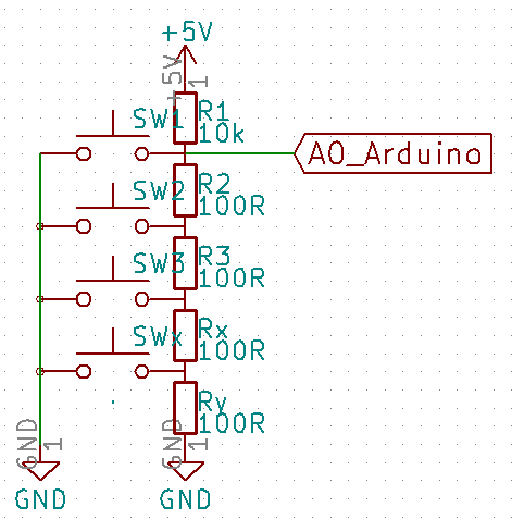
With the Serial.println debug statement one has to determine the correct analog values for the adc_key_val array (start with the lowest value first) by pressing the keys one by one, add approx 30 to the average values per button you see in the serial monitor too have some margin.
-
Hello.
Thanks for the answer, now I'm working on finding the arduino resistor values. -
This is a nice simple solution. There is one downside that is worth noting, pushing multiple buttons at the same time will throw it off. If that isnt a concern it will serve well.
-
Hello
first of all, excuse me for my english, i'm french.
I try to use the sketch with the 10 relays, but nothing works on the buttons.
I tried with several resistance values using "analogread" to read the real values, but when I enter the values in the table nothing happens at the relay levels.P.S: the relays work with jeedom.
can you give me the procedure to follow to properly "configure" the sketch?
cordially
Hello! It looks like you're interested in this conversation, but you don't have an account yet.
Getting fed up of having to scroll through the same posts each visit? When you register for an account, you'll always come back to exactly where you were before, and choose to be notified of new replies (either via email, or push notification). You'll also be able to save bookmarks and upvote posts to show your appreciation to other community members.
With your input, this post could be even better 💗
Register Login