My 1AA battery sensor
-
@klim Hows the battery life looking?
-
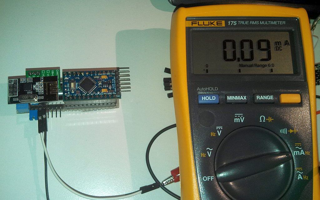
Hi, based on the results of my last measurement the sensor needs 90µA, while sleeping + consumption for transmitting, but this depends on the configuration.
The theoretical battery life just for sleeping (without battery self discharge) should be:
2500mAh/90µA=27777h
27777h/24h=1157d
1157d/365d/3,17a -
@klim : Nice idea and thanks for documenting it here!
Following @tbowmo I am wondering what is the effect of the stepup converter very close to the antenna; although the converter will work in the kHz range, it harmonics can be in the 2.4 GHz range and quite loud, so it could be that some channels are worse than others. Also the coil can induct currents in the traces of the NRF24L01 board.
I am not so worried about the metal of the battery, that will impact the antenna pattern and maybe the impedance but the overall energy transmitted will be largely the same.
But, that is all theory would be good to know if you see any drawback.
I do not see a capacitor on the NRF24L01 board between the 3.3V and GND. Looks like you have one on the board but I think you can improve things by adding a low-ESR capacitor on the NRF24L01 board see http://www.mysensors.org/build/connect_radio
-
Hi, based on the results of my last measurement the sensor needs 90µA, while sleeping + consumption for transmitting, but this depends on the configuration.
The theoretical battery life just for sleeping (without battery self discharge) should be:
2500mAh/90µA=27777h
27777h/24h=1157d
1157d/365d/3,17a@klim said:
Hi, based on the results of my last measurement the sensor needs 90µA, while sleeping + consumption for transmitting, but this depends on the configuration.
The theoretical battery life just for sleeping (without battery self discharge) should be:
2500mAh/90µA=27777h
27777h/24h=1157d
1157d/365d/3,17aI'm basically asking because everyone states that the step-up pulls like 1ma even arduino is in sleep. Your saying yours is not doing that?
-
@daulagari:
I'm aware of that it is not the best option to mount them close to each other, but as it is just a prototype nearly everything is allowed :-)
I did a quick test with success on a distance of 5m through a cement-wall of 20cm width.
A capacitor for NRF24l01 is already on board, it's the grey one with a capacity of 4µ7. I know it's just an ordinary aluminium capacitor and not low-ESR, but i had nothing other at home.@that0n3guy:
Again tested at battery side: 90µA @ 1.5V --> 135µW. Take a look here:
-
Tried to search google to back up my theory, but I failed at it :sa:
So I turned to a group of fellow electronic nerds, asking them how to measure things.. The conclusion from their responses is:
Use DC current measurement, if your multimeter is good at averaging things. Otherwise, use a oscilloscope with a series resistor, and use integral maths to calculate the real current usage..
So I was wrong in my assumptions.. Sorry :)
-
This was also my method (using an oscilloscope to integrate the current), but...I found it difficult to measure the very low currents...µA range with an oscilloscope (these are very high quality Tectronics units, we have many at work, but there is some DC offset even though I calibrated the probe, yada yada yada). So, on some more recent measurements I used a Keithley bench multimeter with averaging. I guess the final test is to see how long the batteries (or battery) actually last.
-
I know about the problems and accuracy for very low current measurements without special instruments. Therefore i want to buy a µCurrent Gold adapter soon, it is a very cost effective way to measure very low currents. This adapter with the combination of a digital oscilloscope with math is what we need here. But at the end as therik already said: the final test is to see how long the battery actually last
-
Well, if its pulling ~1mA, then it should only last about a month or two. (right?)
You could also pull battery voltages to see the battery "level" as well.
-
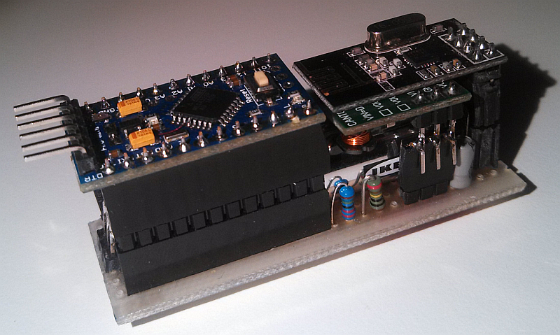
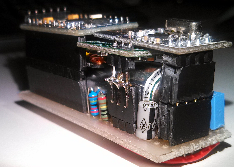
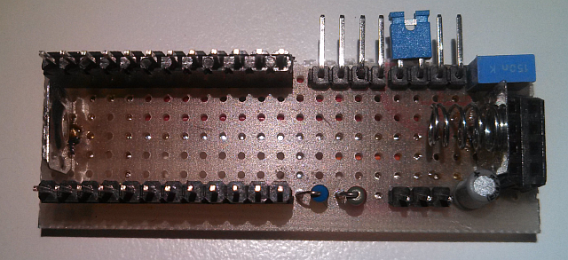
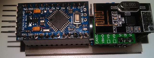
Hi, i want to present you my working but not really sexy looking single cell AA battery sensor. It is as it is - under development and was just made to get some experience about power consumption and physical size.
I thought a lot about the type of battery to choose, but at the end i desisted to use an ordinary AA cell. I know about the advantages and disadvantages of different battery chemistry and types, but in the aspect of price/mA the AA battery is still the winner. Self discharge of a few years is acceptable for that type of battery.
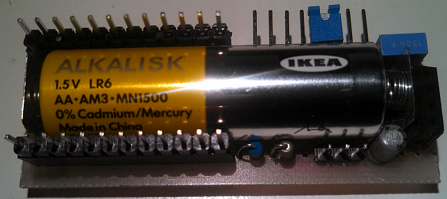
Another aspect i followed is, just to use buy-able and assembled modules, as i don't have enough time to build my own arduino board, or battery management (step up), etc. .....The core of the sensor is the battery itself. The components are mounted around the battery. The sensor can be completely disassembled in a few seconds, as the modules are just connected with pin headers.
The power consumption for sleep is around 90µA, if i can believe my Fluke 175. The power consumption of normal operation and transmit i don't post here, because of two reasons:- I was not able to get a good measurement result with a multimeter. I should integrate the consumption over time to get a real result.
- The lifetime of a sensor is dominated by the sleep consumption, not by the operating consumption (if transmission time is just a few times per hour)
There are still some improvements to do, but ehh, this is just a prototype.
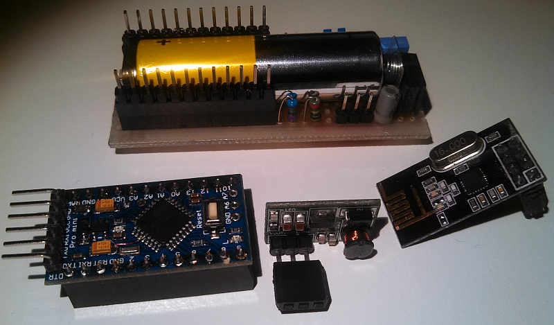
Used components:
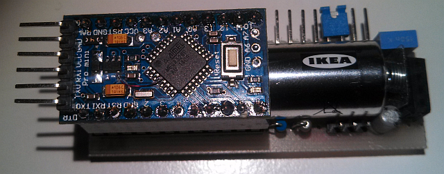
-Arduino pro mini 3.3V @ 8Mhz (mcu board)
-NRF24L01 (wireless board)
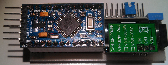
-3.3V StepUp (0.8V-3.3V from Canton electronic an ebay product link)Modifications:
-Arduino board: Cut LED
-Arduino board: Cut LDO
-StepUp board: Cut LEDPhysical dimensions (without pin headers):
65mm x 22mm x 25mmWhich values the sensor can send?
In general this is just a battery monitor, as i want to get some experience of power consumption, but the pin header is able to work with various types of sensors. I use a simple DS18B20 temperature sensor on the header pins.Here are some pictures:
Overall view1
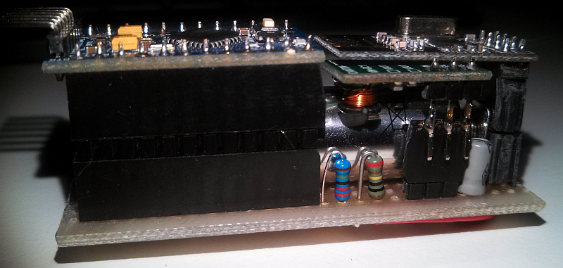
Overall view2
Overall view3
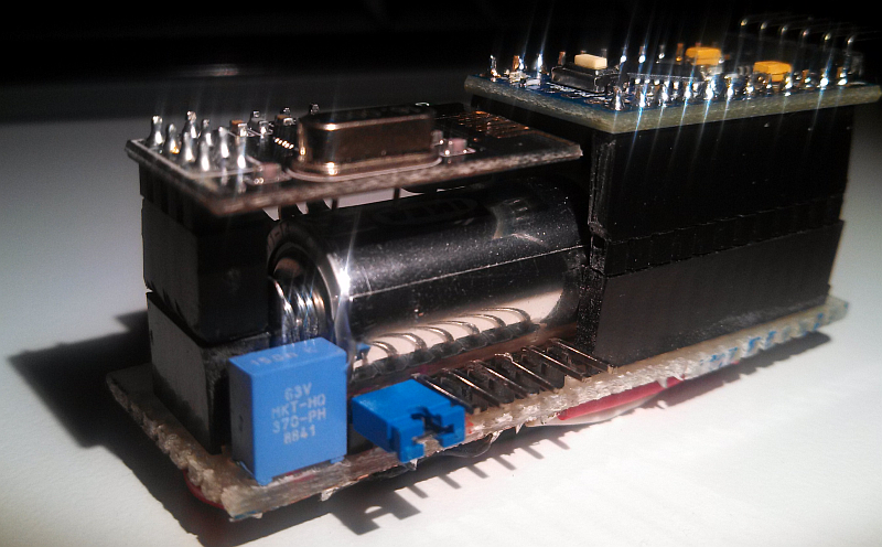
Overall view4
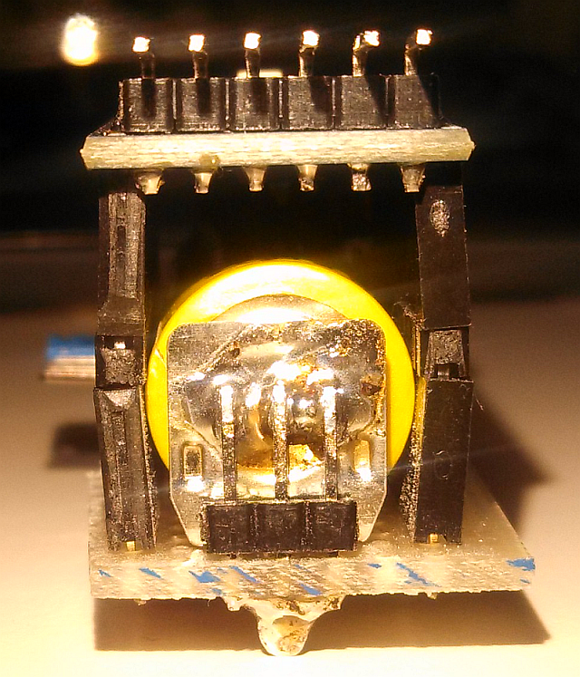
Unused space over battery, but i didn't had the correct pin headers at home "mea culpa"
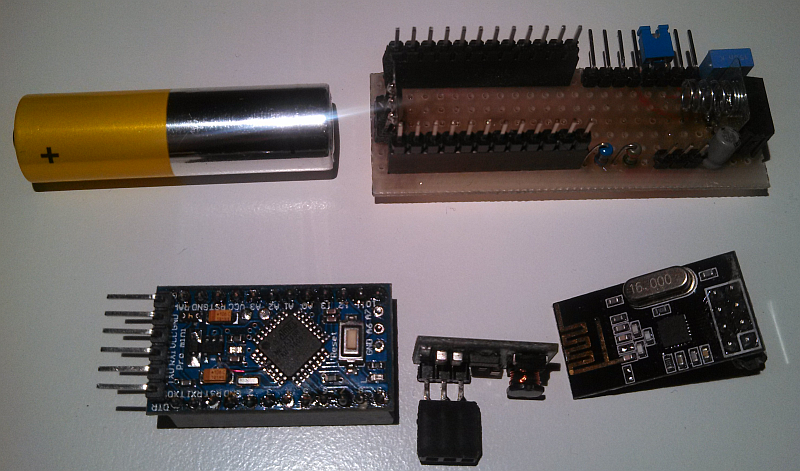
Disassembled view1
Disassembled view2
Assemble view1
Assemble view2
Assemble view3
Assemble view4
Assemble view5
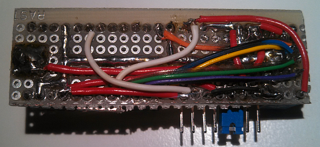
Bottom view (remember - just a prototype)
I hope i could give you some potential ideas for your own project.
Questions, suggestions, feedback, all is welcome. -
Looks like it has been a year or two now. Is it still going on the original battery?
Hello! It looks like you're interested in this conversation, but you don't have an account yet.
Getting fed up of having to scroll through the same posts each visit? When you register for an account, you'll always come back to exactly where you were before, and choose to be notified of new replies (either via email, or push notification). You'll also be able to save bookmarks and upvote posts to show your appreciation to other community members.
With your input, this post could be even better 💗
Register Login