$8 Lamp (Outlet) "Smart Plug" Module
-
I like the idea of logo stickers. Better in some ways than typical swag like t-shirts and coffee cups, because if it goes on the devices we build that provides useful information, not just advertising. Maybe leave a blank section where a node number could optionally be written in with a sharpie, or a version.
Maybe "Networked by MySensors.org" rather than powered? ("Telepathy by MySensors"?)
-
Dome Stickers would be nice ;)
http://www.aliexpress.com/item/Custom-Made-with-Your-design-Clear-Dome-Resin-Sticker-Epoxy-Stickers-Label-1000pcs-free-shipping/1875126113.html?spm=2114.031010208.3.1.zlyb2BJust wonder how we should make them cost-effective to buy for the community...
-
Dome Stickers would be nice ;)
http://www.aliexpress.com/item/Custom-Made-with-Your-design-Clear-Dome-Resin-Sticker-Epoxy-Stickers-Label-1000pcs-free-shipping/1875126113.html?spm=2114.031010208.3.1.zlyb2BJust wonder how we should make them cost-effective to buy for the community...
-
The domes are kind of cool for some things, but I think for this purpose I'd actually prefer flat stickers that fit smoothly on any side of a project box, even curved, without protruding and looking like something that should be pressed, or that should light up.
(OTOH domes atop an illuminated button (assuming translucent backing) would be awesome in some cases)
And with flat, (re) distribution in small batches is easier - one could get a lot of them in a minimum-postage conventional letter.
-
Hi Pete,
I'm thinking of using the AMS1117 3.3v regulator. Can I still use the 0.1uF and 10uF capacitors or do I need to use others. Because I run into sites saying I need to use 100uF and 1000uF and I think the difference is pretty big.
Regards,
Kenney
btw: Great video! It helped me a lot!!
-
Hi Pete,
I'm thinking of using the AMS1117 3.3v regulator. Can I still use the 0.1uF and 10uF capacitors or do I need to use others. Because I run into sites saying I need to use 100uF and 1000uF and I think the difference is pretty big.
Regards,
Kenney
btw: Great video! It helped me a lot!!
@Kenney-R said:
I'm thinking of using the AMS1117 3.3v regulator. Can I still use the 0.1uF and 10uF capacitors or do I need to use others.
Yes, that should be fine. The capacitors are there to help filter the power to the radio (which can be sensitive).
-
Regarding adding wires to the on-PCB antenna of a nRF24L01+ module, here's someone who used two wires (andcut some traces) to create a dipole. He knew that it was hard to really calculate the appropriate values, so he did empirical testing to find the best lengths, using a test program.
http://www.instructables.com/id/Enhanced-NRF24L01/
And is this from the same Pete or another one?
https://www.youtube.com/watch?v=NpMnauHeR7Y -
Another interesting (albeit long) video testing range of various modules and antennae.
https://www.youtube.com/watch?v=gtM832Z0ujE
The interoperability of different types is somewhat surprising. Some had only a 2/3 packet success ratio even at close range, but retained that for a long distance, for example. He did try cap vs no cap, and with "whip" (really more of a stubby or rubber ducky style) antenna parallel or with one pointing at the other. The unit with PA+LNA and shield was overall pretty good for range.
-
@petewill
Now i got three working relays thanks to you, so again, great video!
Wanted to thank you and also show my sollution.
I hade some 433mhz cheap (not good working) relays with perfect case i could re-use:
The case had a status-led and a switch i use as well.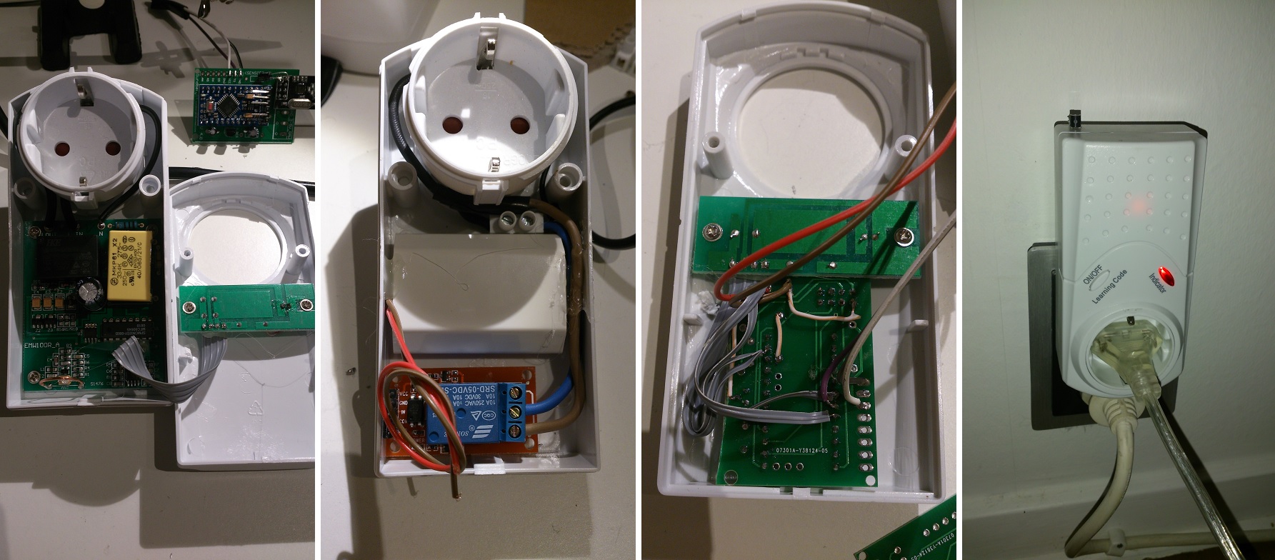
@sundberg84 how are you powering the arduino?
-
@dayve218
Im using a USB charger as pete does in the video but mine is a iphone charger instead of a samsung. -
Nice project, both Petewill and sundberg84.
I was just wandering if you @sundberg84 know more about what is the device type/model/manufacturer you were moding?I've used quite some time and effort to find localy some good case that I can modify, I did manage to hack some of them but they are just not quite reliable (something with power just kills caps too often).
Thanks in advance, sorry for bringing up old topic (but it is a very good one :) )
-
@dakipro - Its a low brand 433mhz wall plugs i bought in Sweden called Everflourish emw100r. I dont think they are sold anymore. Its probably some china brand so maybe they are sold in another name.
-
So I have been thinking of building some relay controlled power strip nodes similar to these, but there have been some issues that I have been thinking about. The first is that if I am going to use a relay to turn on an outlet, the relay would need to be powered the entire time that I would want that device on. This would mean that not only am I powering the device that is plugged in, but the power to keep the relay on also. Wouldn't it be smarter to use latching relays? At least with those you don't need to keep power to the relay while your outlet is on. Has anyone ever done a MySensors node with latching relays? If so, how do you manage monitoring the state of the device?
-
out of the curiosity, what is downside of powering the relay entire time?
that is how (all) wall switches work out of the box, you press the button and they turn on/off by powering the relay (all the time).
I think that they work quite reliably when it comes to keeping power to the reley -
out of the curiosity, what is downside of powering the relay entire time?
that is how (all) wall switches work out of the box, you press the button and they turn on/off by powering the relay (all the time).
I think that they work quite reliably when it comes to keeping power to the reley@dakipro I wouldn't say that ALL wall switches work that way. And when you say (all) wall switches, what are you referring to? Standard (non automated) wall switches don't use relays. Also, most if not all of the X10 relay modules and wall switches that I have use latching relays.
-
I meant these typical automated/controlled wall switches mentioned in the topic http://www.nexa.se/vara-produkter/system-nexa/mottagare-paav/eycr-2300
I opened 6-7 different ones to find the right casing for some projects, and they all had "regular" relay that goes back when the power is off (thus being powered the whole time). Of course I didn't open every single one of them, that is why I put (all) in parentheses.
I am also not the expert on the relay topic, that is why I asked what is the downside :) -
Hi All,
I created a second "Smart Plug" and thought I'd make a how to video this time. I have found them very useful for controlling various devices around the house. It's long but hopefully will be good for everyone including those not too familiar with MySensors. I know when I was first starting out I had little to no experience with any of this stuff and it was hard to piece it all together.
Here is the parts list (most of this stuff can be obtained from the my sensors store so don't forget to support them!)
- 1 Gang Outlet Box
- Outlet
- Computer power cord or extension cord
- Old cell phone charger or some other 5v power supply
- Items from MySensors Store http://www.mysensors.org/store/
- 22-24 gauge wire or similar (network cord)
- Female Pin Header Connector Strip
- Prototype Universal Printed Circuit Board
- NRF24L01 Radio
- Arduino Pro Mini
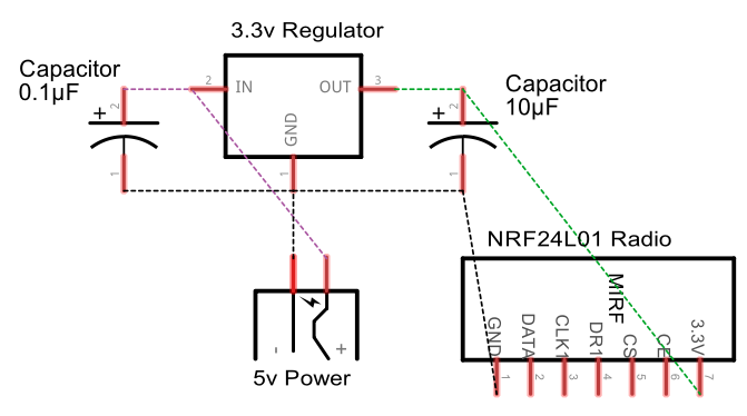
- Capacitors (10uf and .1uf)
- 3.3v voltage regulator
- Female Dupont cables
Here is a wiring diagram for the 3.3v regulator:
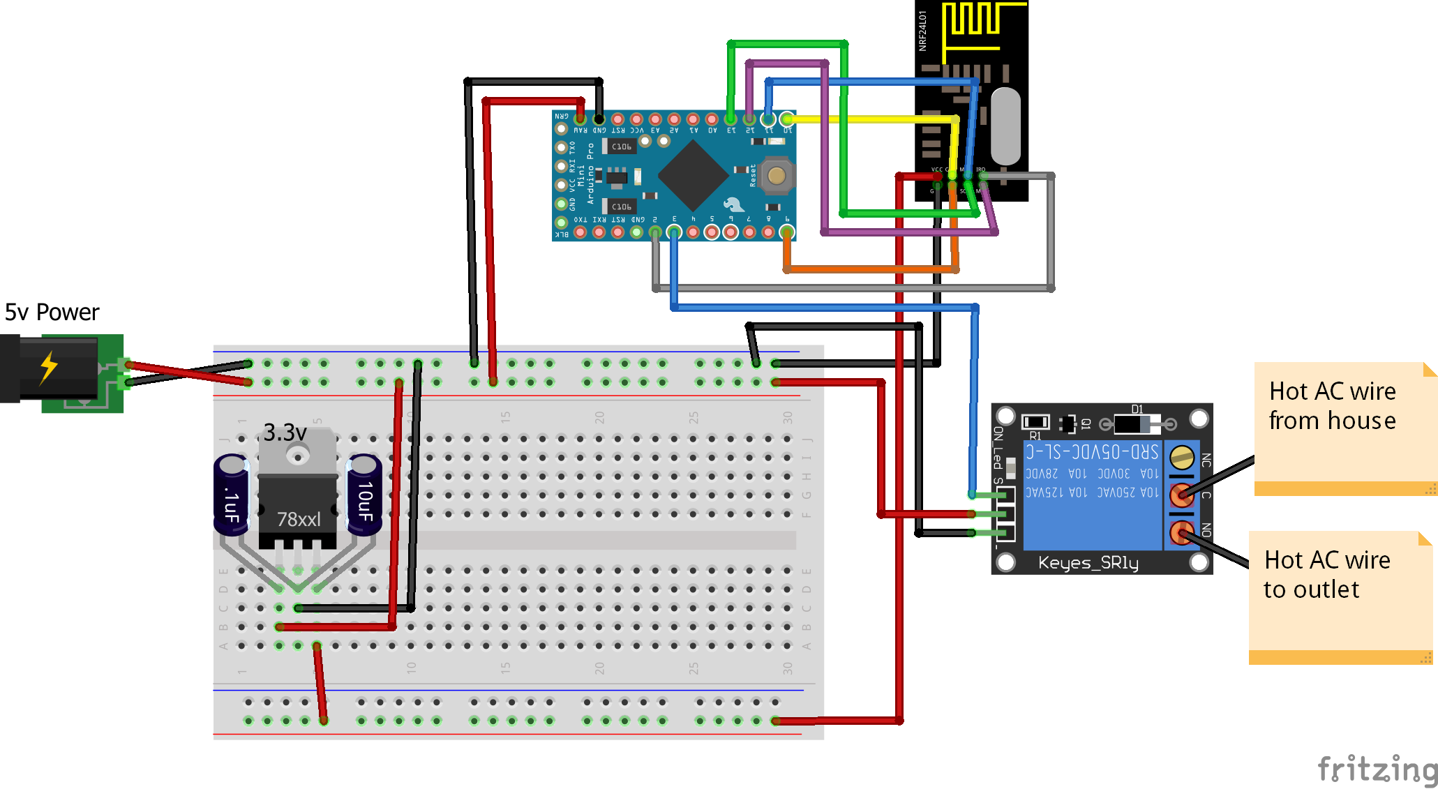
Here is the code I used. I made a few customizations but the example "Relay Actuator" code can be used as well.
https://codebender.cc/sketch:72358*edited to add wiring diagram
@petewill greetings sir.. Im getting error in your source code.. Maybe imported a wrong library.. Sir can i ask where did u get your MySensors.h library.. I get mine in codebender..
My error is..
MySensor gw;
MySensor does not a nametype
Hello! It looks like you're interested in this conversation, but you don't have an account yet.
Getting fed up of having to scroll through the same posts each visit? When you register for an account, you'll always come back to exactly where you were before, and choose to be notified of new replies (either via email, or push notification). You'll also be able to save bookmarks and upvote posts to show your appreciation to other community members.
With your input, this post could be even better 💗
Register Login