$8 Lamp (Outlet) "Smart Plug" Module
-
I dont reallt wants to admit it...
Well, I ordered the 5v relay from ebay (i have the reciept!) and looking at petewill video it says SRD-05VDC-
Looking at mine it says SRD-12VDC so probalby the sent me a 12v relay...New one will arive soon i hope :) Thank you for the help and sorry for clogging the thread.
Controller: Proxmox VM - Home Assistant
MySensors GW: Arduino Uno - W5100 Ethernet, Gw Shield Nrf24l01+ 2,4Ghz
MySensors GW: Arduino Uno - Gw Shield RFM69, 433mhz
RFLink GW - Arduino Mega + RFLink Shield, 433mhz -
I dont reallt wants to admit it...
Well, I ordered the 5v relay from ebay (i have the reciept!) and looking at petewill video it says SRD-05VDC-
Looking at mine it says SRD-12VDC so probalby the sent me a 12v relay...New one will arive soon i hope :) Thank you for the help and sorry for clogging the thread.
@sundberg84 that makes so much sense! And its not even your fault! :-)
-
I dont reallt wants to admit it...
Well, I ordered the 5v relay from ebay (i have the reciept!) and looking at petewill video it says SRD-05VDC-
Looking at mine it says SRD-12VDC so probalby the sent me a 12v relay...New one will arive soon i hope :) Thank you for the help and sorry for clogging the thread.
-
@sundberg84 said:
Hi @petewill!
I made this :) Great video :+1:I think i get bad reception or something because it works the first 5-6 times and then nothing...
This could also be a power or a wiring issue. But, the antenna is an easy modification so it wouldn't hurt to try this first. Another test is to move the device closer to your gateway. If it still stops after 5-6 times then it probably isn't communication issues.
In the end you describe an cat5 wire added as antenna because of bad reception.
Do you remove the plastic/shielding so its just copper?
Im afraid to short anything out with a long uncovered antenna if thats the case...No, I left the shielding on the wire. Sorry, I should have specified that.
and if i hear you right its 3,28 inches which should be 33,31200 millimeters on the antenna?
I think 3.28 inches is 83.312 millimeters (at least that's what google says it is).
-
@petewill
Just out of interest: how did You come up with the length for the antenna?
I remember vaguely that You can calculate the length if You know the
used frequency but You connect Your wire to an already existing PCB-Antenna...Christoph
@hyla I actually recently did a separate video on how I do this with a little more explanation. If you're interested it's here:
In summary, I measured the length of the existing antenna on the PCB then added additional wire to get it up to the required length for the 2.4GHz range (4.92 in).
-
Thanx :)
Meanwhile I did some research too. The formula (as You all know :) ) is:
Lambda (m) = c(m/s) / f(1/s) with
c= 299711000 m/s
f= 2.400.000.000 hzwhich comes down to 0.1248795833333333 m or roughly 4.92 in
The 1.64 in that are used on the PCB are actually Lambda/3.Nicely done, Pete :)
C.
-
@petewill
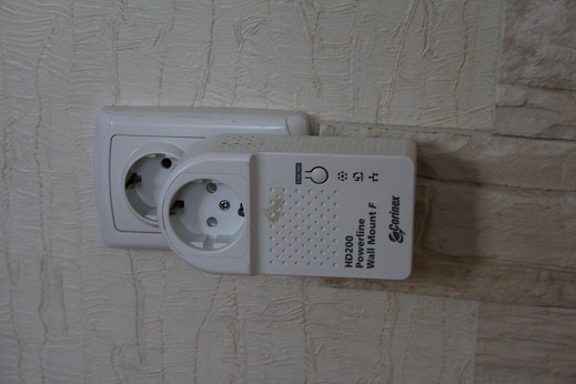
Now i got three working relays thanks to you, so again, great video!
Wanted to thank you and also show my sollution.
I hade some 433mhz cheap (not good working) relays with perfect case i could re-use:
The case had a status-led and a switch i use as well.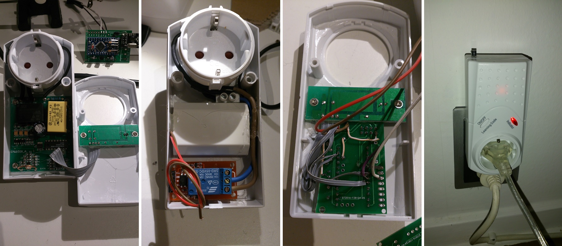
-
@petewill
Now i got three working relays thanks to you, so again, great video!
Wanted to thank you and also show my sollution.
I hade some 433mhz cheap (not good working) relays with perfect case i could re-use:
The case had a status-led and a switch i use as well. -
@petewill
Now i got three working relays thanks to you, so again, great video!
Wanted to thank you and also show my sollution.
I hade some 433mhz cheap (not good working) relays with perfect case i could re-use:
The case had a status-led and a switch i use as well.@sundberg84
Nice! That one deserves its own project thread. I think we're many interested in the details. -
This is may realisation
-
@hyla I actually recently did a separate video on how I do this with a little more explanation. If you're interested it's here:
In summary, I measured the length of the existing antenna on the PCB then added additional wire to get it up to the required length for the 2.4GHz range (4.92 in).
Hi @petewill
I've tried this and had inconclusive results rather then a significant extended rage. Not sure what I'm doing wrong or if it's the quality of my RF module.
I've used some wire (8.33 cm) I had left over but its not one solid copper wire, its has many "strings" inside. In your experiment did you use one solid copper wire and can this influence this hack?
Thanks
-
Hi @petewill
I've tried this and had inconclusive results rather then a significant extended rage. Not sure what I'm doing wrong or if it's the quality of my RF module.
I've used some wire (8.33 cm) I had left over but its not one solid copper wire, its has many "strings" inside. In your experiment did you use one solid copper wire and can this influence this hack?
Thanks
@barduino I am using solid copper cat5e wire. I don't know much about antennas but it may change the behavior. Do you have any old cat5 that you can cut and test with?
My "How To" home automation video channel: https://www.youtube.com/channel/UCq_Evyh5PQALx4m4CQuxqkA
-
@barduino I am using solid copper cat5e wire. I don't know much about antennas but it may change the behavior. Do you have any old cat5 that you can cut and test with?
I'm going to try it.
I'm also using a capacitor on the RF module, not sure if you did combine both techniques.
On a last note, I've noticed some power setting on the MyConfig.h (1.5 lib) cant remember the values form 1.4.1
/**********************************
*  NRF24L01 Driver Defaults
***********************************/
#define RF24_CE_PIN		   9
#define RF24_CS_PIN		   10
#define RF24_PA_LEVEL 	   RF24_PA_MAX
#define RF24_PA_LEVEL_GW   RF24_PA_LOW
So now I'm initializing the gatweway as
// Instanciate MySersors Gateway
MyTransportNRF24 transport(RF24_CE_PIN, RF24_CS_PIN, RF24_PA_LEVEL);
instead of
// Instanciate MySersors Gateway
MyTransportNRF24 transport(RF24_CE_PIN, RF24_CS_PIN, RF24_PA_LEVEL_GW);
Not sure if there is a significant diference here...
The results i'm getting now (after removing the antena, but with capacitor and changes on 1.5 MyConfig) are similar to the results I got from lib 1.4.1 with capacitor. I have a repeater about 15 meters from gateway and if i put it 17 meters it doesnt work anymore (there are some walls on the way)
I'll just add a solid copper antena to see if results change.
Thanks for the info!
Cheers
-
I'm going to try it.
I'm also using a capacitor on the RF module, not sure if you did combine both techniques.
On a last note, I've noticed some power setting on the MyConfig.h (1.5 lib) cant remember the values form 1.4.1
/**********************************
*  NRF24L01 Driver Defaults
***********************************/
#define RF24_CE_PIN		   9
#define RF24_CS_PIN		   10
#define RF24_PA_LEVEL 	   RF24_PA_MAX
#define RF24_PA_LEVEL_GW   RF24_PA_LOW
So now I'm initializing the gatweway as
// Instanciate MySersors Gateway
MyTransportNRF24 transport(RF24_CE_PIN, RF24_CS_PIN, RF24_PA_LEVEL);
instead of
// Instanciate MySersors Gateway
MyTransportNRF24 transport(RF24_CE_PIN, RF24_CS_PIN, RF24_PA_LEVEL_GW);
Not sure if there is a significant diference here...
The results i'm getting now (after removing the antena, but with capacitor and changes on 1.5 MyConfig) are similar to the results I got from lib 1.4.1 with capacitor. I have a repeater about 15 meters from gateway and if i put it 17 meters it doesnt work anymore (there are some walls on the way)
I'll just add a solid copper antena to see if results change.
Thanks for the info!
Cheers
@barduino Yes, I always use a capacitor to filter power to my radio. I recently have been using 3.3v Pro Mini Arduinos so I have just been putting a 4.7uf cap very close to the radio.
As far as I know the RF24_PA_LEVEL_GW is only used for the gateway. You can change the power level in the config file for the sensors but it looks like you already had it at the MAX. You can play with the power level depending on your radio model used with the gateway. On my gateway I experimented with an external antenna type radio and if it was set on max it completely wrecked my z-wave communication (there must have been interference like crazy since they are different frequencies). If you are using the PCB type antenna you can probably increase the power level to max without any issues. It's been a while since I did anything with my gateway (it's been working great for months) so I don't remember what settings I'm using. I do know I have the antenna hacked radio instead of the external antenna.
-
One thing to note is that adding an external antenna extension to the on-PCB antenna moves this into the realm of "RF magic". What I mean is that it becomes a very non-standard sort of hybrid antenna about which we can predict very little. Like receiving television with rabbit ears and aluminum foil, you will mostly have to work by trial and error rather than exact calculations.
The on-PCB antenna should already be tuned for the RF wavelength, probably near the middle of the band. We can also calculate the appropriate length for a straight wire used INSTEAD OF the on-PCB. But when we solder a wire onto the PCB antenna, we wind up with a very complex antenna which may or may not work very well (but in general it's far easier to make a random antenna work poorly than to make it work well). There are questions of antenna gain (or attenuation), but also of directionality - adding the wire might make it transmit/receive better in some directions and worse in other directions!
Part of my point is that we cannot necessarily predict the best length of wire to solder to the on-PCB antenna by using the calculations that would apply with no PCB antenna. It may depend where on the PCB antenna trace you solder the extra wire, and perhaps on how the wire gets bent (especially if it comes near electrical conductors).
So after you have the node placed where you want it (including the orientation), you can try moving the added antenna around in the case for better reception - and you can also try changing the wire length because 8.33 cm is not necessarily optimal for this hybrid antenna. Of course it's easier to shorten a wire by just successively chopping off a little bit at a time; you can solder in a new wire if need be.
The length does not have to be super precise by the way - a loose wire antenna is not a highly tuned (Hi-Q) antenna and a slightly suboptimal length doesn't dramatically alter the results. Which is good, since the modules operate over a range of frequencies - and because even without the PCB antenna to really complicate things, even the PCB trace between the chip and the wire is part of the tuning as well, not just the bendable wire.
Stranded wire vs solid should not have a large effect, compared to the many other factors involved here.
-
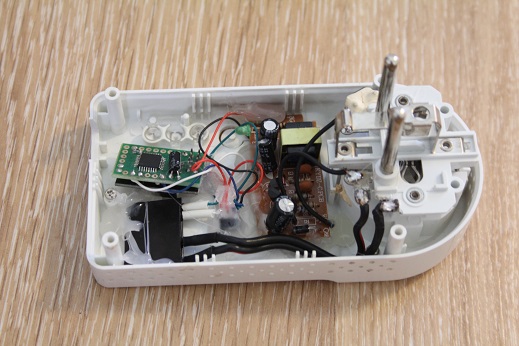
Hi Pete,
I'm new to this forum, but I wanted to give you a big thumbs up. I really enjoyed watching your videos and I learned a lot from watching them. It's because of people like you that made me decide to start using MySensors.
I have an old 433Mhx power plug that is broken. I see if I can turn it in to a MySensors power plug ;)
-
@Zeph I agree. This is complicated stuff that I don't even begin to grasp. That said it is a cheap and easy hack to try. In my case it has helped every time. Maybe I just got lucky but it helped enough of my nodes that I thought I'd at least tell people about it. If it doesn't work, then just remove the wire and no harm done. Thanks for all your contributions to the site. Your knowledge is helping a lot of people.
@TheoL Thanks for the kind words! Although, credit really goes to @hek and the team. They are the geniuses that make this all work! Good luck with "mysensoring" the old power plug. But, be careful, it's addicting. :)
-
@petewill just to be clear - I appreciate your posting that adding the loose wire to the on-PCB antenna helped, and I'm not discouraging that. If it works, it works! Mostly I wanted people to understand that it's going to be trial and error, rather than something where they can count on calculating the best length (because it's added to another antenna at an unanticipated point, rather than being a standalone wire antenna). It would not surprise me if somebody found that a 6.5 cm wire worked better than 8.33cm, for their particular case (picking an example length at random). Wiggle those rabbit ears!
I love the examples you post and your excellent videos. I have modestly good knowledge here and there, with gaps in other places, and your working examples give me confidence/inspiration to build something I haven't before - along with practical (not just theoretical) advice. You even turn your minor mistakes into lessons - how it should have been done, and how you managed to work around it anyway. Keep them coming!
@Zeph said:
Mostly I wanted people to understand that it's going to be trial and error, rather than something where they can count on calculating the best length (because it's added to another antenna at an unanticipated point, rather than being a standalone wire antenna). It would not surprise me if somebody found that a 6.5 cm wire worked better than 8.33cm, for their particular case (picking an example length at random). Wiggle those rabbit ears!
I agree. The more knowledge provided to people the better hopefully it will result in better communicating nodes. Thanks for the posts!
-
@Zeph I agree. This is complicated stuff that I don't even begin to grasp. That said it is a cheap and easy hack to try. In my case it has helped every time. Maybe I just got lucky but it helped enough of my nodes that I thought I'd at least tell people about it. If it doesn't work, then just remove the wire and no harm done. Thanks for all your contributions to the site. Your knowledge is helping a lot of people.
@TheoL Thanks for the kind words! Although, credit really goes to @hek and the team. They are the geniuses that make this all work! Good luck with "mysensoring" the old power plug. But, be careful, it's addicting. :)
@petewill Off course I'm very gratefull for what @hek and the team created. I've been playing with mySensors for a week now. And I'm still amazed by it. It's so easy to use. And I haven't had a failure yet. I'm currently promoting MySensors to everyone I know ;-).
@hek Do you happen to have some small stickers with the MySensors logo? Ik would love to put them on the sensors I create. Something like "Powered by MySensors"?
Hello! It looks like you're interested in this conversation, but you don't have an account yet.
Getting fed up of having to scroll through the same posts each visit? When you register for an account, you'll always come back to exactly where you were before, and choose to be notified of new replies (either via email, or push notification). You'll also be able to save bookmarks and upvote posts to show your appreciation to other community members.
With your input, this post could be even better 💗
Register Login