What did you build today (Pictures) ?


  • Made a prototype board for writing a software for one of my projects. Goal was to have everything needed on a board no bigger then a 1.54" eink display, and to make it doable at home by my own.
    I was gladly surprised that everything worked (after a sleepless night of fighting through-layer connections, and soldering/desoldering FPC connectors) 🙂 The only I've messed up is order of connector pins, so the display is connected the wrong way...
    IMG_20200723_172110.jpg
    IMG_20200723_162420.jpg

    It also has pads for SHT30 sensor so it may be somehow useful after development is done.


  • @monte said in What did you build today (Pictures) ?:

    FPC

    Excellent handwork. I also dealt with such FPC conectors :), here are the correct FPC conectors - https://aliexpress.ru/item/32794813863.html


  • @berkseo Thanks!
    Link doesn't open. I have the right ones, I've just messed up PCB layout. Somehow pins on the board goes in the wrong direction, so the most left pin is #24 instead of #1 🙂


  • @monte fixed the link, html.... not htm


  • @monte By the way, this version of screens is discontinued, it is better to develop software for new versions


  • @berkseo thanks for mentioning that. But as I understand the change in software would be just including another header file, if I'm using GxEPD library. There is a mention on github that there is GDEH0154D67 model as a replacement for GDEP015OC. Or do you mean that they are discontinuing 1.54" displays completely?


  • @monte said in What did you build today (Pictures) ?:

    Or do you mean that they are discontinuing 1.54" displays completely?

    Yes, I mean that these displays are no longer produced. And it is better to focus on new ones.


  • @berkseo well, that's a shame. They are the perfect size for my purpose. I guess I need to stock few of them, while I can 🙂 Thanks for the tip!


  • @berkseo said in What did you build today (Pictures) ?:

    @monte said in What did you build today (Pictures) ?:

    Or do you mean that they are discontinuing 1.54" displays completely?

    Yes, I mean that these displays are no longer produced. And it is better to focus on new ones.

    Just to clear up a potential misunderstanding: The 1.54" EPDs aren't going to vanish anytime soon. Only the GDEP015OC1 has been discontinued and the GDEH0154D67 may follow, too at some point.

    But Dalian Good Display has just launched the GDEW0154M09 this month, which seems to be the successor of the GDEH0154D67 at first sight. There is also the GDEW0154M10, which supposedly has a better contrast due to a new manufacturing process. Waveshare seems to be still selling their version of the GDEH0154D67, but not any of the new ones.

    I don't think you need to hoard them like other poeple hoard their live-long stock of toilet paper these days. 😉


  • My super simple NRF51 touch buttons. I mostly use these to toggle overhead lights that I've converted to Tasmota.

    Screen Shot 2020-07-27 at 9.21.20 AM.png

    Screen Shot 2020-07-27 at 9.22.01 AM.png

    Screen Shot 2020-07-26 at 3.16.10 PM.png


  • Hero Member

    @ncollins Elegant. Does it talk to a gateway, which then talks to your Tasmota, or does it somehow talk directly to the Tasmota? So many things now have Bluetooth as part of them that the possibility of direct communication sometimes exists.


  • @NeverDie Buttons -> Mysensors Gateway -> OpenHab Rules -> Tasmota Switches / Outlets / Extension cords.

    I am tempted to explore the BLE route. It seems to support a majority of my sensor use cases, I like the idea of standardizing on the GATT protocol, and there are already a ton of tools and connectors in place.


  • @ncollins And this is my simple capacitive button, just a button:). Beginning of this story was like this:... once I bought a Chinese capacitive button and was very upset with the quality...
    IMG_20200728_170232.jpg


  • @tbowmo said in What did you build today (Pictures) ?:

    atmega32u4

    Next step: build an entire keyboard and flash QMK to it!
    Nice project, I thought about something similar but to operate a fan, which is way harder than communicating with a computer, I should have started with that.
    Very little nice sensor that one...


  • @monte Where do you buy that e-ink displays? they look awesome


  • @berkseo nice! Just today, I've ordered something similar but with an led mounted sideway, to make more diffused glow of the opaque resin that will cover these:
    6757ae58-33e1-4f37-a7a0-c3031b854aa0-image.png

    @Danielo-RodrĂ­guez I've bought mine on aliexpress, but you can find them at several different places. They are produced by a company named Good Display (Dalian Good Display Co., Ltd to be precise). They have different sizes and colors with different price and performace too. Also they are sold by Waveshare, but the displays are the same, I believe.


  • The other day I received PCB of a long-awaited project. Yesterday and today, I soldered the device, designed and printed the case of the device. It works, wow!!!
    photo_2020-07-28_03-18-09.jpg
    photo_2020-07-29_02-25-59 (3).jpg
    photo_2020-07-29_02-25-59 (3).jpg
    photo_2020-07-29_02-25-59.jpg


  • Hero Member

    I'm surprised no one here has built anything Covid19 related--even something as basic as a handwashing timer or something like that. I, for one, am tired of singing songs to time myself, and getting kids to handwash for the full recommended duration is, well, something I'd rather let automation enforce instead of me! 😉


  • @NeverDie From these things, which are in the photo above, can make an informant COVID-19. Show the trend, the number of infected people to date in your location, and so on.


  • Mod

    A MySensor'ed temperature controller for my utility cabinet, which runs too hot due to all the electronics in there (cable modem, router, switch, etc.)
    In its current version it is able to control a 12V 120mm PWM fan, and reads the temperature from 3 DS18B20 temp sensors (inlet, 'ambient' and router).
    Later I might add a temperature controller to keep the ambient temperature stable at a a few degrees above inlet, by controlling the fan's dutycycle.

    As all sensors in my utility cabinet are powered from 5V USB, I used a step-up converter to generate the 12V required by the fan.

    v1.jpg

    After soldering everything together I wasn't happy with the orientation of the JST headers for the temp sensors, so a small PCB was added to mount them under 90 degrees:

    v2.jpg

    All data and control is routed to Node-red, stored in InfluxDB and graphed in Grafana:

    c7ff7fd0-44f4-4a33-9ec8-e7e03ce7aaf5-image.png

    You can see the temperature of the router ('USG') go down with increasing fan rotational speed (lower chart, 'rpm.mean').
    Temperature decrease is not as big as I hoped for, so I might need to install a fan with a bigger airflow.


  • My new gateway with leds for state and the only node I have: A wireless arcade button controller ea084163-e43a-4aad-ae0c-993085b04502-image.png


  • Mod

    @Danielo-RodrĂ­guez you might already be aware of this, but all that metal close to the nrf24 antenna will probably block some signal.


  • Well, it not really a build I plugged in wires, and copied code. Found a random usb charger and put it all in my workspace to be.

    And I absolutely love this thing. Maximum of 3 hours work. I was having fun, so it could be more.

    I considered that there could and should be a display on this thing, but not for now. I made this, because I have never experimented with temperature sensors and I just received a few. Now I can just see what happens with the temperature in there.
    sensor is a AHT10 temperature and humidity.
    http://www.aosong.com/m/en/products-40.html
    I used this library: https://github.com/enjoyneering/AHT10
    I repurposed Hek's DHT code, and swapped the readings with the AHT's

    IMG_20200815_095309.jpg

    shed before
    IMG_20200531_192231_2.jpg

    workspace after but still filling it.
    IMG-20200812-WA0001.jpeg


  • Today I've finally swapped my outdoor relay node with something descent.
    IMG_6784.jpg
    This was my very first mysensors node that I've built when I was only starting to mess with arduino, probably around four years ago.

    IMG_6785.jpg
    IMG_6786.jpg
    This board uses cheap 5v power supply and an amplified version of NRF24 module from Ebyte. It supposed to be poured with silicone ore resin, but I am yet to find suitable box, the size of this board appeared to be bigger then most of such cases designed for compound pouring. But I'm planning on making next version, with non-isolated power supply, which will help to achieve smaller size.


  • My new project of a temperature and humidity sensor with an electronic ink display 1.02 Inch ( GDEW0102T4 ), very low power consumption, very small device.

    DIY Temperature and humidity sensor with an electronic ink display 1.02 Inch ( GDEW0102T4 ) – 06:19
    — Andrew EfektaSB

    IMG_20200909_111923.jpg


  • USB + ESP8266 adapter for W2812B LED strip.

    Well, this is actually a Tasmota + Openhab build, but could easily be MySensors.

    Also worth noting, this 5m 150 led strip draws too much current to reliably use with a USB wall adapter.

    62154743620__8CA02E53-F789-4B83-8D1D-C2E1D4F18423.jpeg

    62154729146__FDB896AA-6E42-4B25-93B1-6214813216EA.jpeg

    Messages Image(2477667489).png

    Messages Image(1253441685).png


  • Mod

    Very nice renderings.

    W2812B uses about 50mA at full brightness, so you'd need a power supply that can deliver 7,500mA if you run the entire strip at maximum.


  • @mfalkvidd Yeah, I realize I can only use a portion of the strip, or keep it very dim. I actually bought this with the hopes of flashing with Tuya Convert, but turns out they switched to non ESP modules. So, I figured I would make my own.

    energizer_EIS2-1001-RGB.jpg


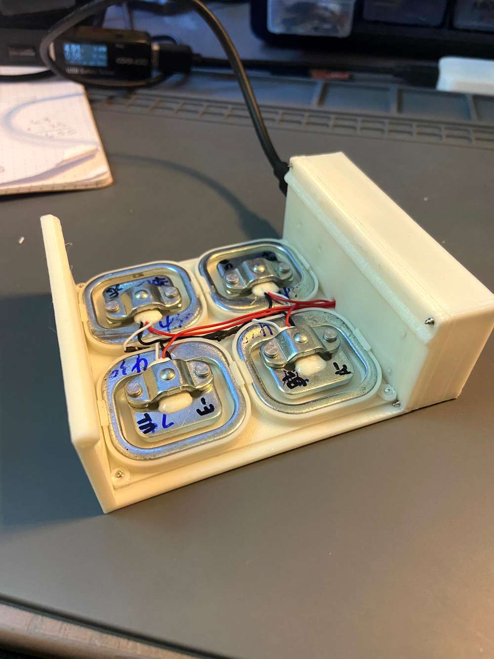
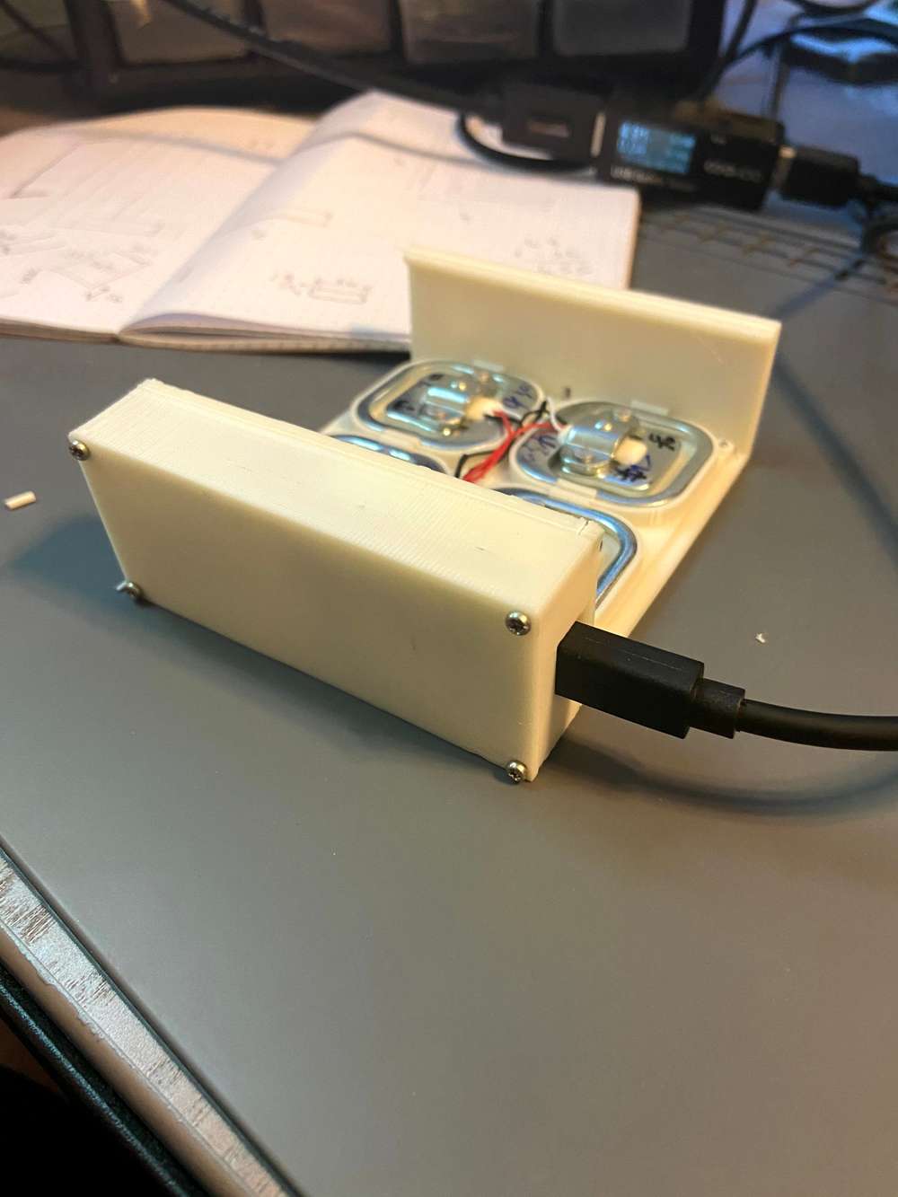
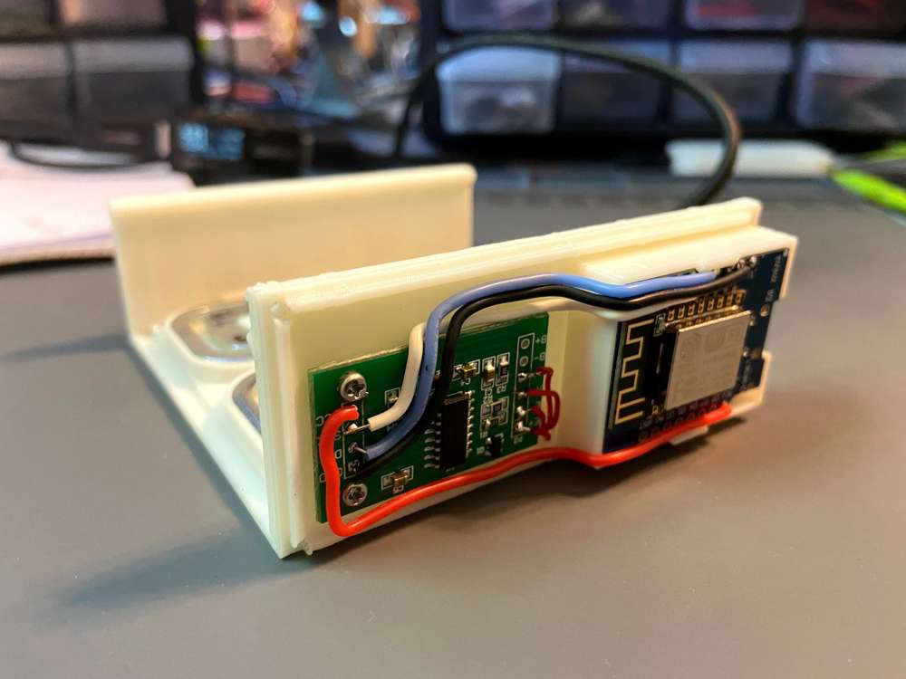
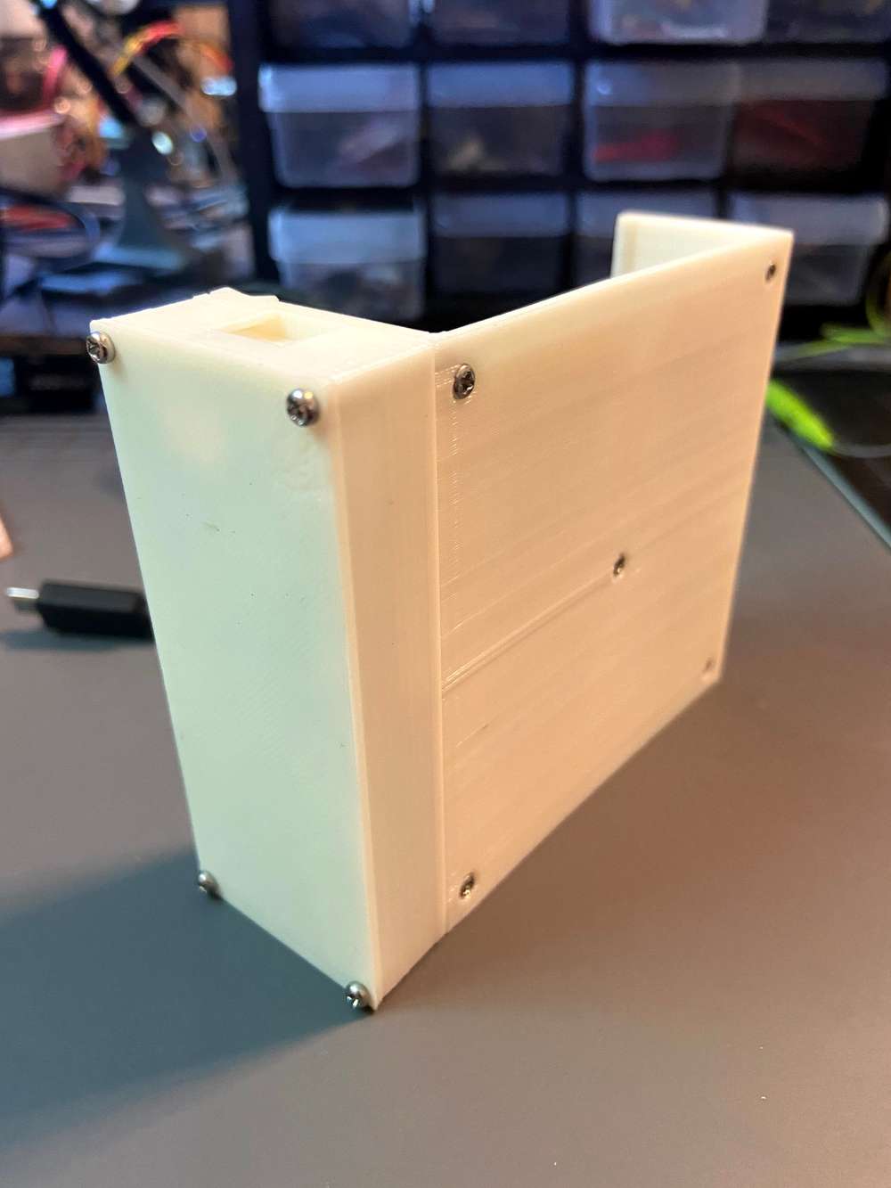
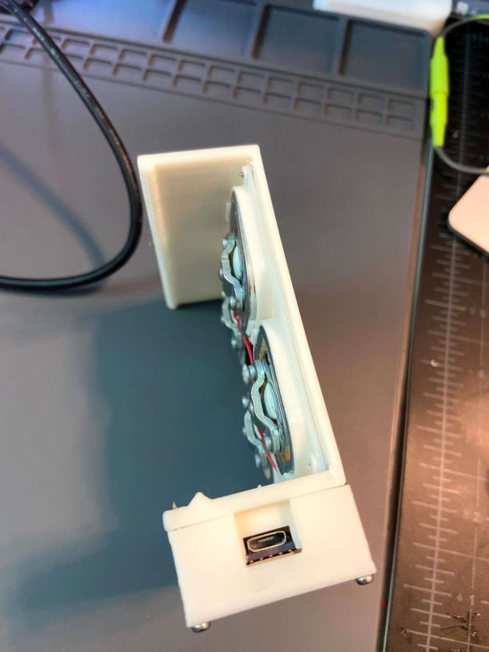
  • A bed occupancy sensor. 4 50kg load cells, an HX711, and a Wemos D1 to make a wifi scale that rests on a bed slat under the boxspring.

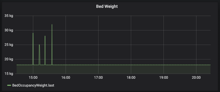
    Given the placement and weight distribution it doesn't turn the bed into a huge bath scale, but definitely accurate enough to use the deltas to estimate if there is someone in the bed. I can also tell when our 12lb (5.5kg) dog is on the bed.

    I have rules in openhab to turn the overhead fan on and off. Also disables some TTS notifications if somebody is in bed.

    IMG_1154.jpg IMG_1155.jpg IMG_1156.jpg IMG_1157.jpg IMG_1158.jpg Screen Shot 2020-09-15 at 8.26.22 PM.png


  • thanks to assistance of some of the people here i now have up and running a front gate controller for my double front gates (Solar powered)

    now have a node that monitors the batteries, knows if the gate is open or closed and has a relay for activating the gate


  • Compact, simple NRF52 motion sensor
    Ebyte E104-BT5032A NRF52832 module
    MH-SR602 Motion Sensor
    LiFePO4 AA Battery

    IMG_1164.jpg IMG_1167.jpg IMG_1166.jpg IMG_1165.jpg


  • MYS PoE MQTT Gateway with 868Mhz LoRa radio in IP55 85mm x 85mm box

    • arduino pro mini 3.3V clone
    • SX1276 with spring antenna
    • W5500 lite
    • 5V 802.3at power over ethernet splitter (gutted)
    • SPELSBERG IP55 box

    gw1.jpeg gw2.jpeg gw3.jpeg


  • My new arduino project wireless weather mini station with electronic ink display 2.9 inches (GDEH029A1), very low power consumption,compact size, housing with magnets. The device can use si7020 / 21, sht20 / 21, HTU20/21D or BME280 sensors. Use the MINEW MS50SFA RF module with nRF5210, nRF52811, nRF52832 chips, or the EBYTE E73 module with nRF52840 and nRF52833 chips. Soon to be available on openhardware.io

    0003.jpg

    0004.jpg

    Video: DIY Mini Weather station with an electronic ink display 2.9 Inch ( GDEH029A1 )


  • Prototype of room sensor for stardard electric box

    IMG_20201025_141753.jpg IMG_20201025_141837.jpg IMG_20201025_141848.jpg IMG_20201025_141942.jpg IMG_20201025_142159.jpg

    Cover is not fully closed to allow air circulation. But I would preffer some method to drill holes/grill into it - any tips to get decent looking result?


  • Hero Member

    @tssk said in What did you build today (Pictures) ?:

    any tips to get decent looking result?

    1. Drill at low RPM so you don't melt the plastic.
    2. If you're going to drill a bunch of holes to make a kind of grill, then preferably use a CNC (even a cheap one!) to drill them so that they don't look hodgepodge.

  • Hardware Contributor

    @tssk - really like your design! Well done.


  • Mod

    @sundberg84 thanks for creating this thread btw. You got the 1st and 1001st post 🙂


  • Hardware Contributor

    IMG_20201026_090317.jpg

    Today im testing and outdoor node in a new PCB, but I had mixed csk and ce on the radio (it's a dual radio PCB).


  • Hero Member

    @ncollins Just wondering: why 4 load cells per sensor instead of only one?


  • @NeverDie

    • At 50kg per cell, 4 would allow me to actually turn the bed into a huge scale if I decided to go down that route
    • I don't believe these are intended to support a significant load for extended periods of time, they can permanently deflect. Given they always have the weight of a king size mattress + boxspring, I wanted to distribute that as much as possible

  • Hardware Contributor

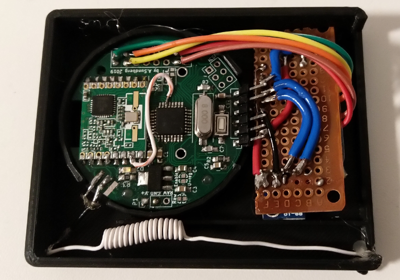
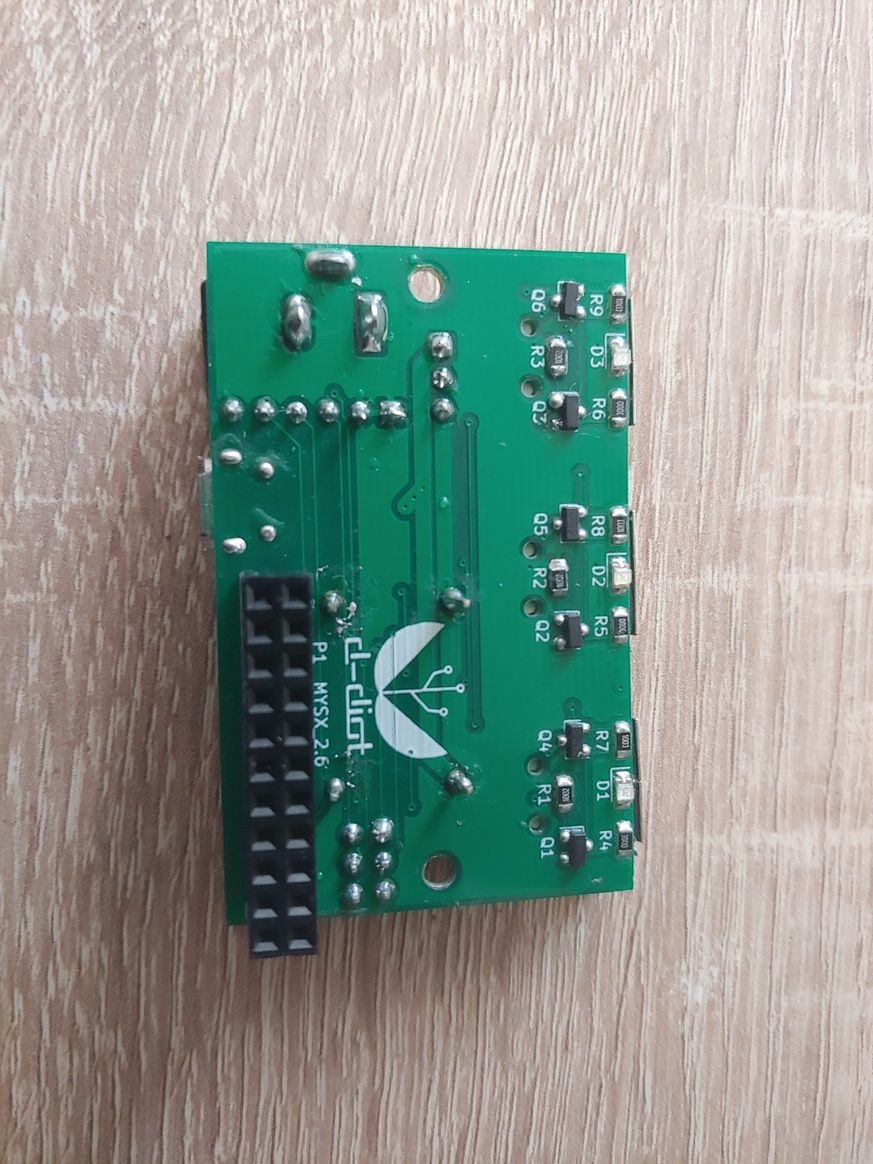
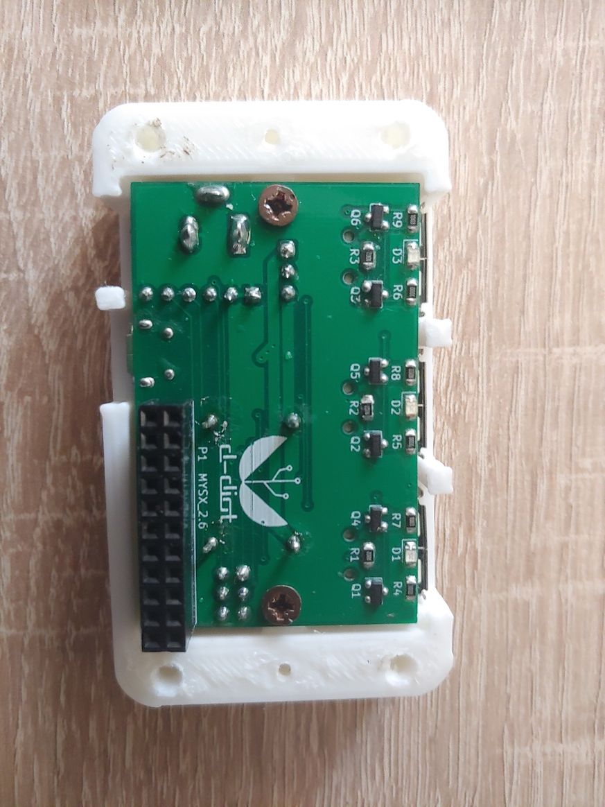
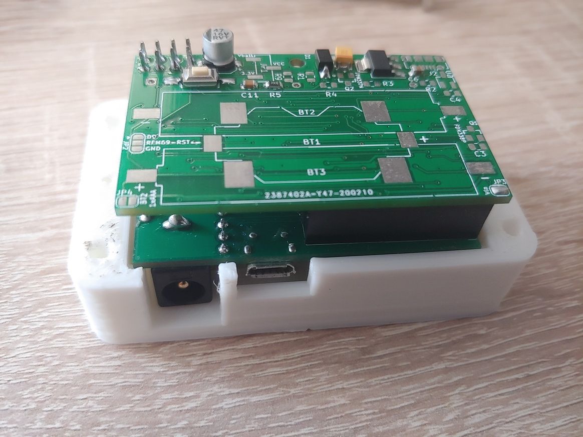
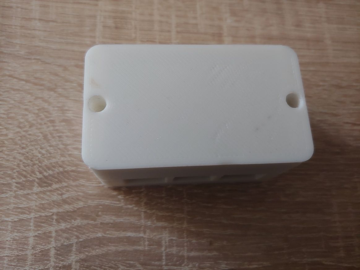
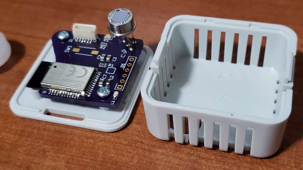
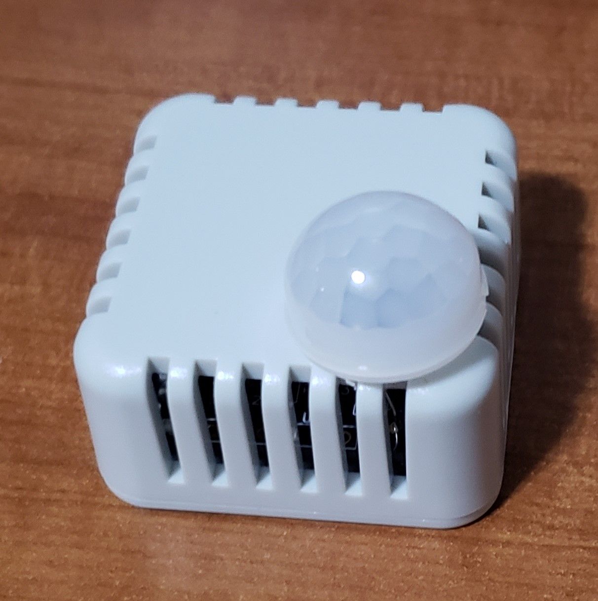
    Current issue: outdoor nodes random stops/disappears - maybe during the time when its high humidity, so trying to try some different approaches i read - this multisensor is getting painted with clear nail polish. Also this PCB is a new board im testing, that Im hoping to be the base for my "final" home automation nodes. Still in dev. but great possibilities!

    75f113be-7ad8-4f12-a9f0-2e237aa57004-image.png


  • Hero Member

    @sundberg84 Gaskets that are held under tight compression seem to work well at holding out moisture. I've seen a number of commercial products that rely on that and only that for in-ground radio sensors.


  • Hero Member

    Here's an example from the new Flume (version 2) water meter monitor:
    gasket_waterproof.jpg
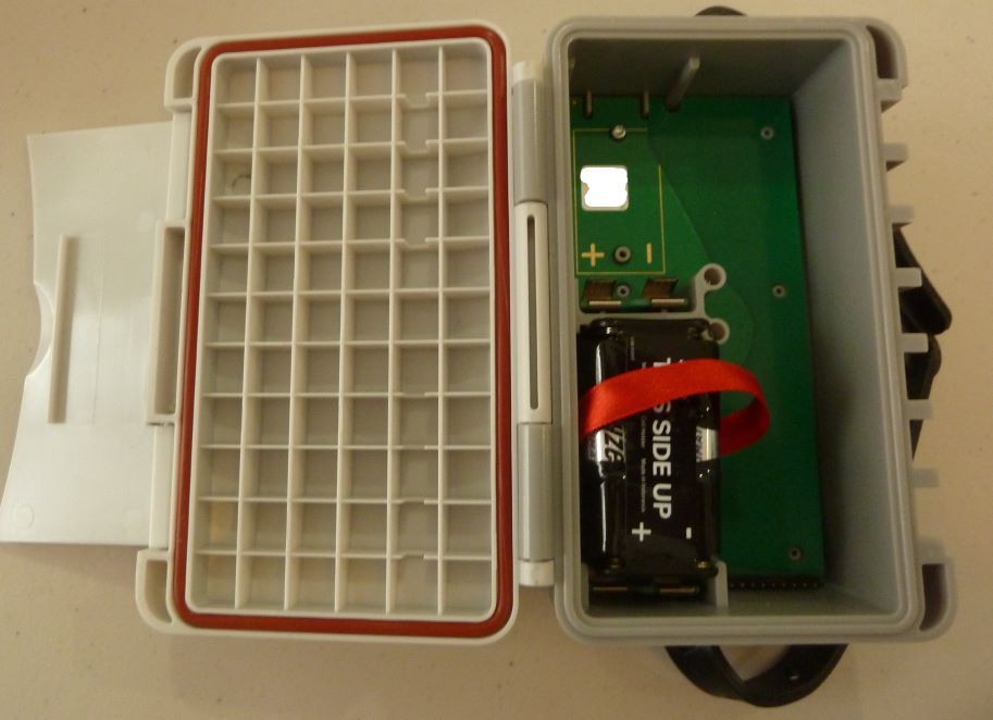
    It gets strapped to your water meter, typically in the ground. All it has is one gasket to seal out everything. This particular box just snaps closed. No screws! Quite a difference from Version 1, which also used a gasket, but had 12 screws holding it snug.
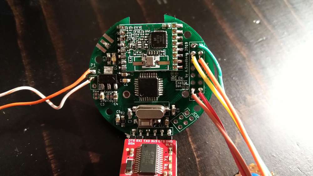


  • @sundberg84 Really like the shape and look of the PCB! I hope I can achieve similar result for my room sensor.


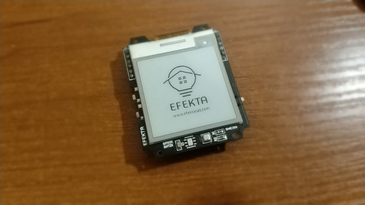
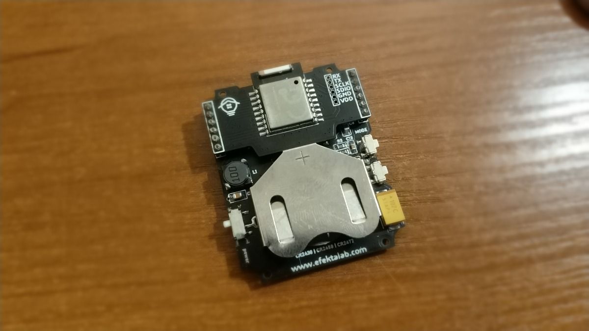
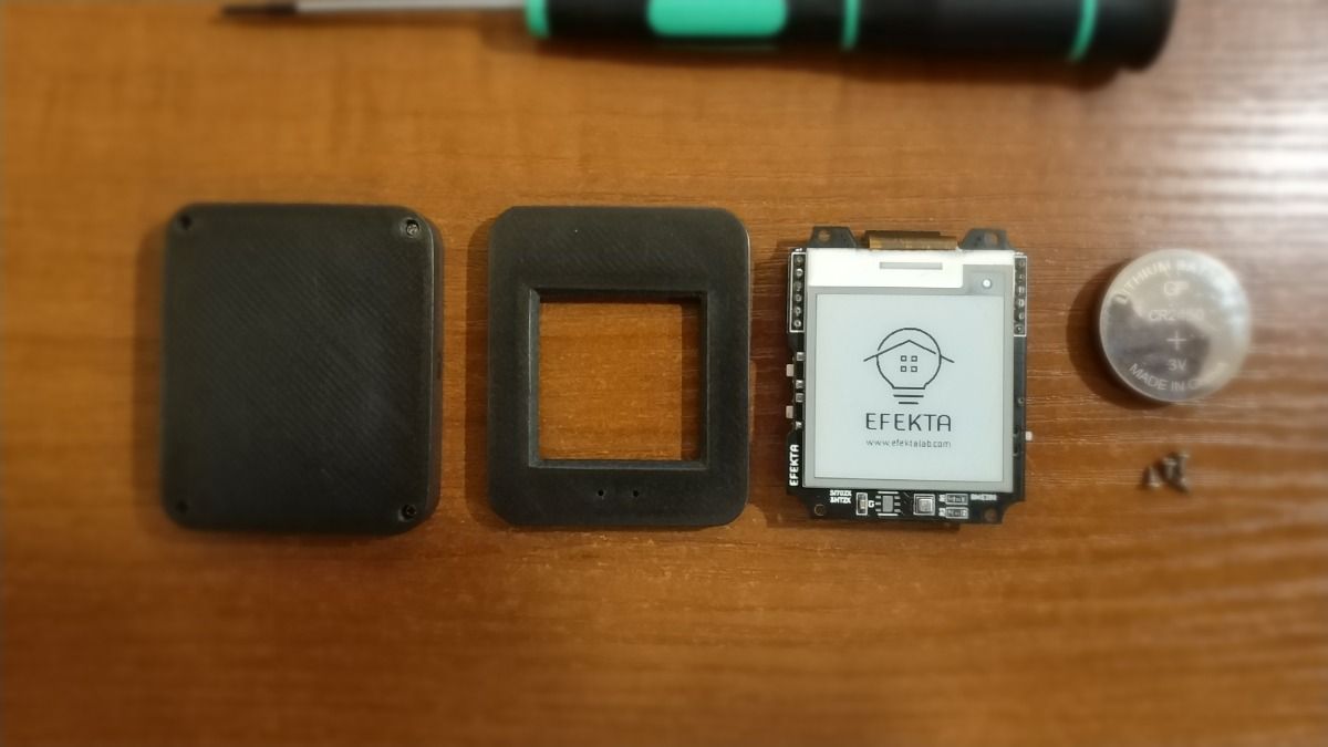
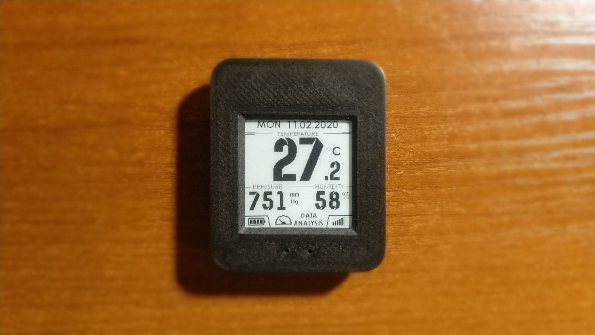
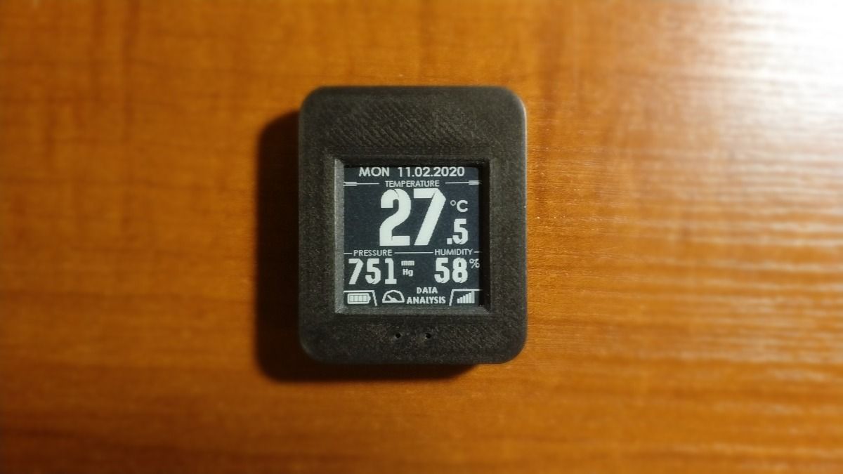
  • And another of my completed projects is a mini weather station running on nRF52832 and nRF52840, you can install bme280 or si7021, htu21d. Powered by a single cr2450 battery. As always soon to be on openhardware.io

    Video: https://youtu.be/HNjYtKyh8zo

    IMG_20201101_232645 (1).jpg

    2.jpg

    3.jpg

    IMG_20201102_015541 (1) (1).jpg

    IMG_20201102_015659 (1) (1).jpg


  • Hero Member

    @berkseo By calling it a mini weather station now you'll need to add an anemometer and rain gauge... 🙂


  • @NeverDie Sorry, I didn't know there were rules like that now :), then it would just be a temperature, humidity and pressure gauge with weather forecasting, okay?


  • Hi guys,

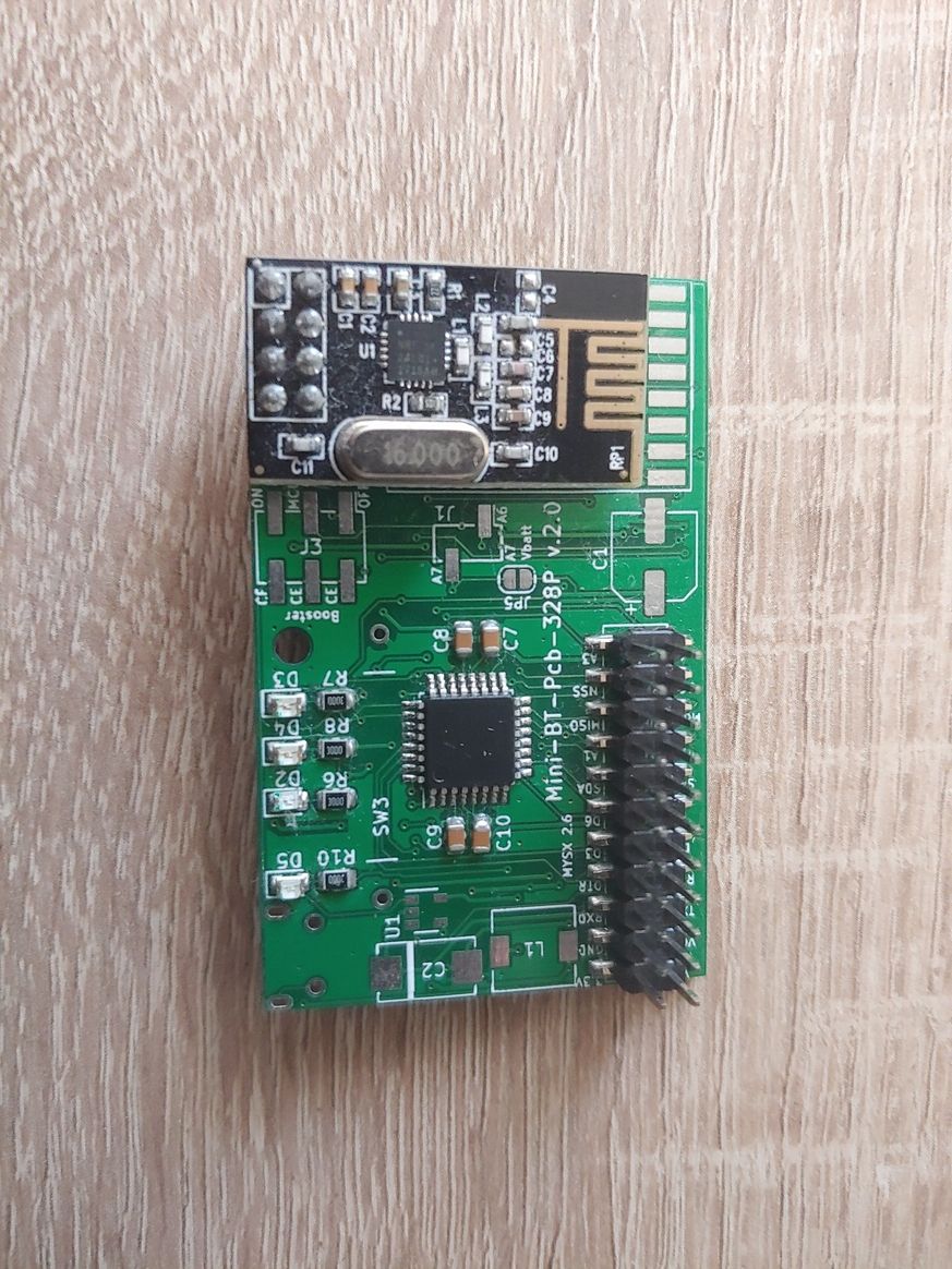
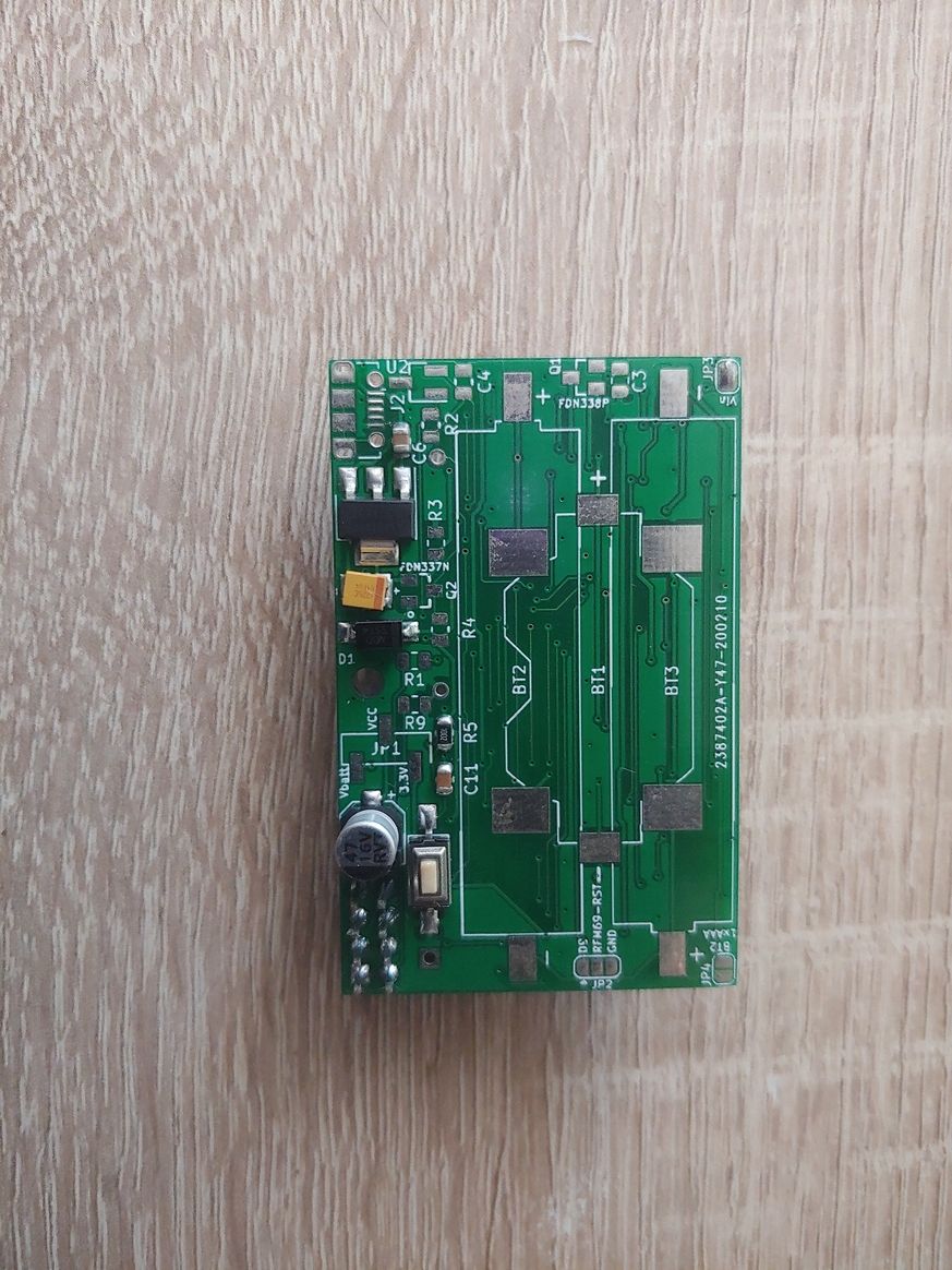
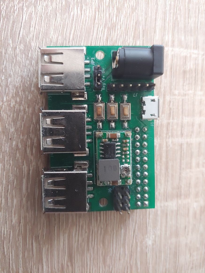
    this is my last node. A 3d printable smart USB power hub.

    20201107_112237_HDR.jpg 20201107_112249_HDR.jpg 20201107_112323.jpg 20201107_113033.jpg 20201107_113043.jpg 20201107_113053.jpg 20201107_140802.jpg 20201107_140813.jpg 20201107_141854.jpg 20201107_141907.jpg 20201107_143615.jpg 20201107_143645.jpg 20201107_144222.jpg

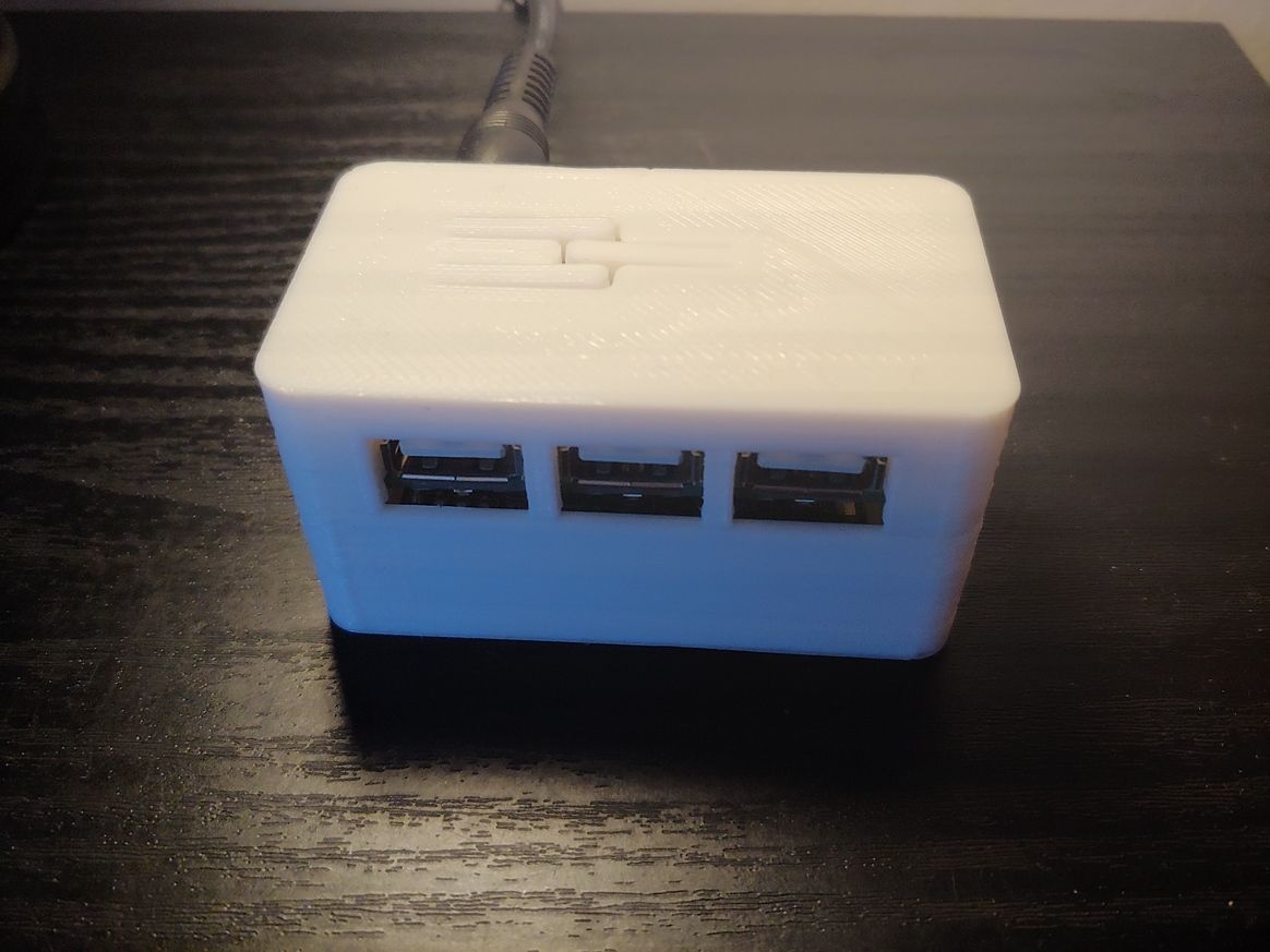
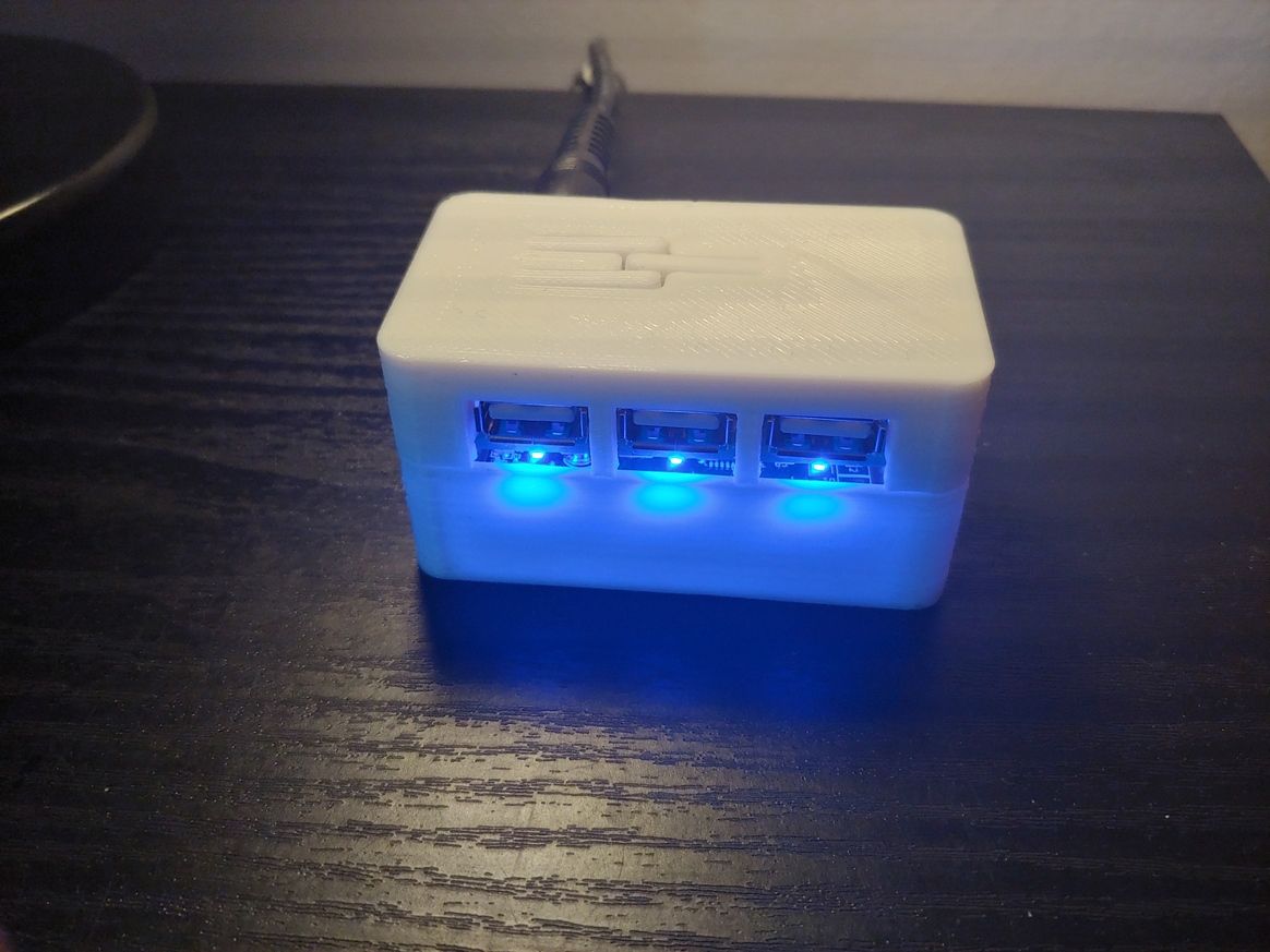
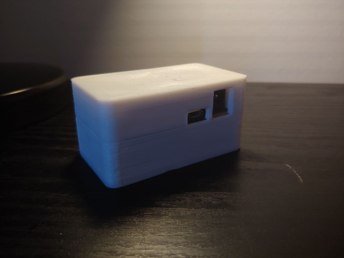
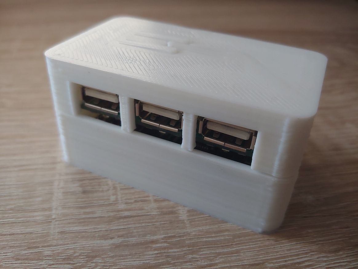
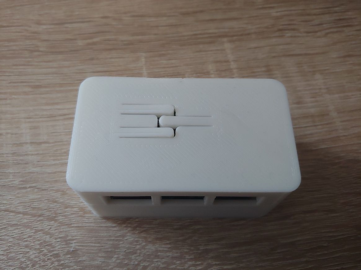
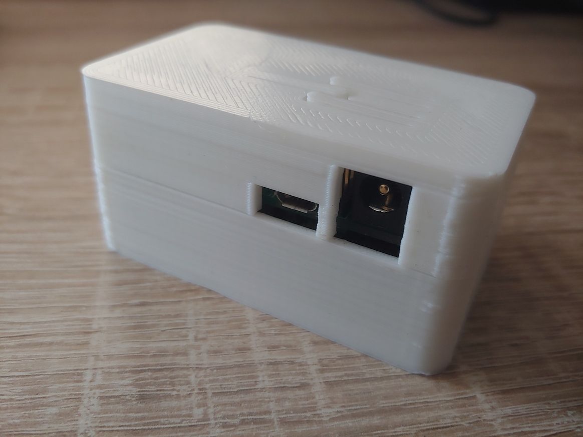
    If someone is interested, here all the details.


  • I am testing a node with a DigiPyro, PYD 1598 motion detector. It is advertised to be low power and runs from 1.8 to 3.6 volts, so should run well with a coin cell. They have to be programmed with several options and I have not found a lot of documentation. I went with what seemed like the most sensitive choices and it seems to work so far. More research needed . ...
    https://www.excelitas.com/product/pyd-1588-pyd-1598-low-power-digipyros

    I bought a couple of these from DigiKey for around $4 each. Now they are more than $12 each and there is no stock. So, these may not be as good a choice as they seemed at first. We'll see . ...

    20201128_190045.jpg
    20201128_190153.jpg


  • The milling topic got my interest and I have been working on getting a machine for myself.
    So far I have just assembled the machine and realised milling is a bit more difficult to start then 3d printing.
    anyway, I would like to share my progress. I am building video's now 🙂

    No circuitsboards yet, but here is a introduction of my way to victory.

    Unboxing the Genmitsu Prover 3018 cnc mill from sainsmart – 03:09
    — Joeri de Man


  • Winter time is tinker time!

    mysensors-epd-node-clean.jpg

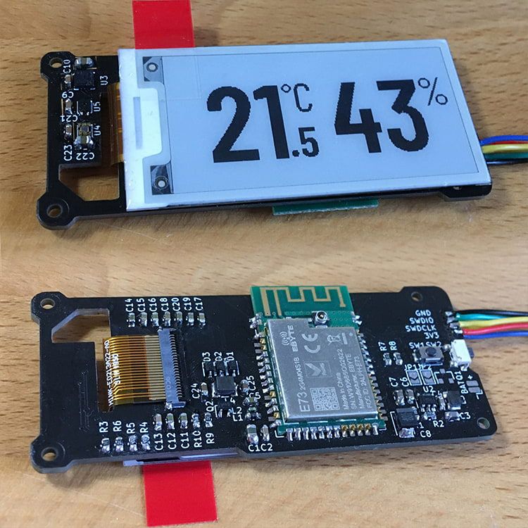
    This is a compact environmental sensor node with an E-Paper display. My goal was to have a decent screen-to-body ratio with a simple and minimalistic display, easy to read from a distance. It is the first design in which I did not use an ATmega MCU. It is also the first time that I used KiCAD instead of EAGLE, soldered no-lead SMD components and worked with an EPD.

    • It features a SHTC3 sensor to measure temperature and relative humidity and a VEML6030 to measure the ambient light, so that I can toggle lights or other appliances in the room based on temperature, humidity or light conditions.
    • I have also added a MEMS sensor (LIS3DH) to auto-detect the device orientation and rotate the EPD image accordingly and / or detect tap events to toggle between different display modes / data sets.
    • It can be powered directly from a 3V source or use the optional 3.3V boost circuit which accepts 1.5V or 3V sources.

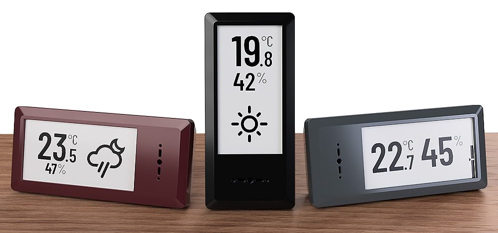
    I finished soldering and testing all the components today and just started programming the rough "framework". Looks promising so far! But still lots to do, including finalizing the 3D printed enclosure. This is how it is supposed to look in the end:

    mysensors-epd-node-render2.jpg


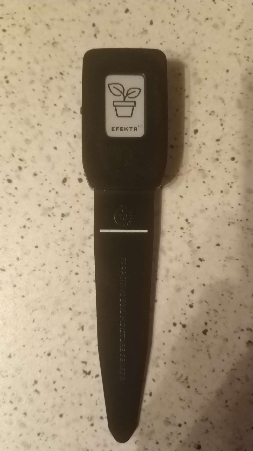
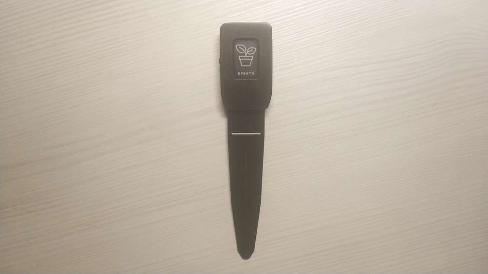
  • Hi guys. I recently made a plant watering control sensor with an electronic paper display. Today I did my first tests, ..everything went well 🙂

    IMG_20210112_155819.jpg

    IMG_20210112_180536.jpg

    Mini plant wattering sensor with e-paper display. First test of hardware and software. – 00:46
    — Andrew EfektaSB


  • @BearWithBeard said in What did you build today (Pictures) ?:

    VEML6030

    Take a closer look at the max44009 light sensor and the lis2dw12 accelerometer. You can save a few microamps.


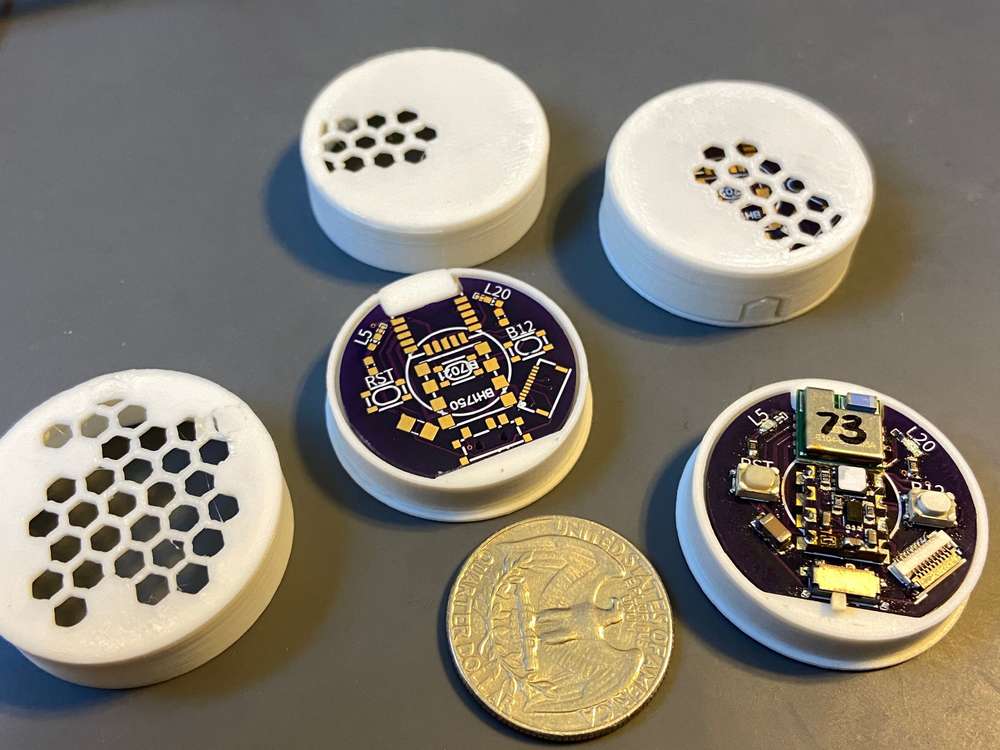
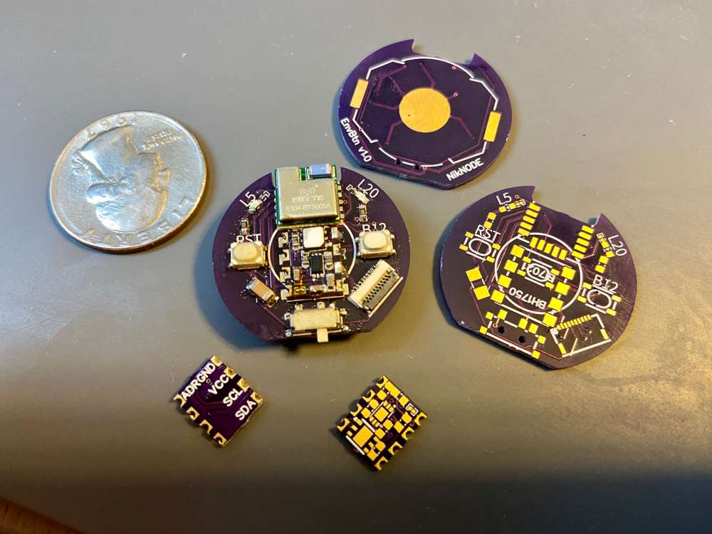
  • First attempt at a modular NRF52805 based board. The smaller board has a Si7021 temp + humidity sensor and a BH1750 light level sensor, both I2C. Ideally, I should be-able to make other sensor boards with the same footprint as long as the sensors are I2C.

    Also included:

    • CR2032 Battery (~1.5 years between battery changes)
    • 10P 0.5 FPC connector for programming and serial debugging
    • 2 LEDs with solderable jumpers
    • On/Off switch (I find this really useful, especially when fighting with coin batteries)
    • RST button
    • Secondary button that I use to force immediate readings
    • Footprint for centered button for alternative use as a remote button (my most common MySensors node)

    IMG_1323.jpg

    I'll post pictures of the enclosure when it's ready.

    I'm also waiting on delivery of a slightly larger version of this board that holds a 2477 battery and a SMD PIR motion sensor.


  • @ncollins
    Very, very beautiful project! I also already have several such radio modules from different manufacturers. Here are just these ebyte specifically, they are without dc-dc. ...I plan to transfer support from nordic sdk to sandeep mistry (just like I did with 52810 and 52811), but how do you flash them under mysensors? Maybe there is already some shorter way?


  • @berkseo Thank you!

    First, I made the compatibility changes to SandeepMistry. This was surprisingly easy. The SDK in SandeepMistry/nRF5-arduino does most of the heavy lifting. I had to modify a few of the precompiler conditions to exclude PWM, change some serial definitions, and update to new handler naming conventions: https://github.com/sandeepmistry/arduino-nRF5/pull/442

    Then, I defined a new Generic NRF52805 variant in mysensors/ArduinoHwNRF5 and handled one assumption of LPCOMP: https://github.com/mysensors/ArduinoHwNRF5/pull/12

    Last, I had to handle a few small assumptions in the MySensors library: https://github.com/mysensors/MySensors/pull/1461


  • Playing around with enclosure designs for my new node
    IMG_1327.jpg


  • @BearWithBeard Very nice indeed!


  • Sensor node on the left, button node on the right.

    IMG_1329.JPG


  • Hero Member

    @ncollins said in What did you build today (Pictures) ?:

    10P 0.5 FPC connector for programming and serial debugging

    How many of the 10 pins do you actually use?


  • @NeverDie Currently using 6, [GND, VCC, SWDIO, SWCLK, - , TX, RX, -, -, -]
    Screen Shot 2021-01-16 at 1.35.18 PM.png


  • The latest addition to my coin cell nodes, a PIR motion sensor based on the Ebyte NRF52805 module.

    The PIR sensor is a Senba S16-L221D-2. I'm measuring around 24uA, which is higher than advertised, but with the 6-7uA from the NRF52805, should still get me 3-4 years on a single 2477.

    IMG_1343.JPG IMG_1344.JPG
    Screen Shot 2021-01-21 at 7.53.33 PM.png
    Screen Shot 2021-01-21 at 7.52.43 PM.png


  • Hardware Contributor

    Today i have assembled the latest revision of my Lighting X3 for DIN rail mounting.
    3.jpg 2.jpg 1.jpg
    5.jpg


  • Hardware Contributor

    Oh yes, I forgot to share photos of my new project - Multinetwork Mysensors Gateway. The main idea of this gateway is that it can at the same time serve up to four different networks (Lora - RFM9X, 2.4 GHz - NRF24 and ISM band RFM69). These networks can be assembled in separate modules and each user can build own set of modules. The incoming stream will be connected via Ethernet on various ports, for example, the gate will have the IP address 192.168.1.128, and each subnet will be served on ports 5003 - the first subnet, 5004 - the second, and so on ...

    7.jpg 6.jpg 5.jpg 4.jpg 3.jpg 2.jpg 1.jpg


  • @kalina looking great! Is it opensource?


  • Hardware Contributor

    @monte Not certainly in that way. In this project, everything is open source with the exception of the board with an ethernet (based on STM32). The ethernet board was developed by my partners and they are not ready to share it yet. But I hope I can persuade them to do it 🙂1.jpg


  • Hero Member

    @kalina I like how it both consolidates and reduces wall-wart clutter all in one stroke. 🙂

    I don't see any antennas though. Where do they go? And does having multiple radios packed close together like that create any noteworthy EMI? I knew a guy who had set up an RFM69 hat on his Raspberry Pi but later found that the raspberry Pi produced a lot of RF noise/EMI that reduced the effective range of his gateway. I don't know whether or not that might happen in your case, but I thought I'd mention it to help with your troubleshooting in the event you notice any unexpected range reduction.


  • @kalina I see. I have the same STM32 chip and was going to use it in one of my next projects, so I asked to get some inspiration 🙂


  • Hardware Contributor

    @NeverDie EMI is a big topic. I think there will be no problems. I am going to do some tests of communication
    quality for various modules and antennas. As for the antennas, I am going to fixed them to the body through the holes, but I have not yet decided on the location. As for connection antenna to the module you can see the on photo ...
    1612440252148.JPEG


  • Hello everyone. I want to show you my new device, battery powered air quality sensor. The device also has light, temperature, humidity, and atmospheric pressure sensors. I am currently testing the software.

    1612636649207.jpg

    1612636649193.jpg

    1612636649221.jpg

    1612636649178.jpg

    1612636649186.jpg


  • Hero Member

    @berkseo I'm curious: which air quality sensor did you opt to build into your device, and what about it did you prefer over the other available air quality sensors that you might have picked, but didn't? Two or three years ago I looked into a few different sensors, but they looked bigger that what you've settled on and their capabilities were pretty narrow. Hopefully the sensor offerings have gotten better since then.


  • @NeverDie sgp40 sensor is used, I also test the bme680, but the results are worse there.


  • My first RFM69 Battery sensor: an ultrasonic sonar to measure the level of my fuel tank (don't laugh, winters can be cold in Burgundy 🙂 )

    Many thanks to @sundberg84 and @mfalkvidd for advice to the Newbie i am and to @Gerator for the RFM69 gateway

    153401744_844840052759734_2548459228707031383_n.jpg

    154871988_184904573009910_6316928321751043541_n.jpg

    154754747_148962677049341_1067850157653395188_n.jpg

    Capture d’écran 2021-02-25 à 20.59.13.png
    Capture d’écran 2021-02-25 à 21.00.18.png


  • Mod

    Nice work @hlehoux!

    Electronics and fuel sounds like a scary combination to me 😨


  • @mfalkvidd You're right: For production i'm going to build isolation for the sensor not to be in contact

    Anyway: The flash point of domestic fuel oil is 55 ° C, which means that fuel oil cannot ignite below this temperature. In addition, in its liquid form, fuel oil is non-flammable at room temperature.


    • Temperature and humidity sensor AHT-10
    • NRF52823 module
    • Power board CR2477
      Connected via MYSX connectors
      Firmware based on NodeManager library

    20210225_115217.jpg 20210213_211620.jpg


  • Hi guys,

    my last creation: the d-diot hub v.3.0

    20210123_205004.jpg 20210124_120658.jpg 20210124_120759.jpg 20210124_120909.jpg 20210214_100204.jpg 20210214_100225.jpg 20210214_100243.jpg 20210123_204437_HDR.jpg 20210123_204535.jpg

    The hub A (wood) is a dual MySensors gateway (RFM69 and NRF24) based on two ESP8266 modules and a BLE gateway + RGB controller thanks to an ESP32 module and ESPHome firmware.

    The hub B (grey and red) is an IR gateway and RC 433 Mhz gateway based on ESP32 modules with an ESPHome firmware. The hub B has also an integrated step-up and step-down voltage regulator based on Arduino Nano.

    To allow the maximum flexibility in placement inside the house, each module can be build as a stand-alone piece of hardware or combined in a single device (see pictures).

    The hub is meant to be used with Home Assistant, the case is 3d printable and as usual, if someone is interested, there is a dedicated wiki page with all the details and the build instructions.


  • I2S/IIC to MYSX converter
    20210303_013732.jpg

    20210302_231755.jpg

    Configurable via jumper matrix
    20210302_231506.jpg


  • Hardware Contributor

    @KooLru - very clever sollution for the lines.


  • @nagelc
    Wow, this is unexpected.


  • I made a simple board to use as a CR2032 battery simulator. It is actually two identical pcb's back to back. I added pins for applying power and another set for measuring current. Now I need a better ammeter. The uA scale works well when sleeping, but the mA scale doesn't seem to pick up the awake current.

    20210516_115836sm.jpg 20210516_115740sm.jpg


  • @nagelc Nice!
    What is the PCB you are measuring on? I'm actually looking for a NRF5 board to use with a coin cell.


  • @electrik

    It's actually at this link posted earlier in the thread: What did you build today (Pictures) ?:
    I mostly use it with BME280 modules for temperature and humidity, but I have tried some other I2C modules in it.
    I'm still experimenting with the motion detector. That will probably get it's own board at some point. It doesn't really fit the enclosure I designed this board for.


  • I think this open source project is finished. This is a small air quality sensor. Quite a useful thing turned out for our not simple time.

    https://github.com/smartboxchannel/EFEKTA-EINK213-AIR-QUALITY-SENSOR-NRF52840-V2-ED3

    IMG_20210524_220731.jpg

    IMG_20210524_220528.jpg

    a.png


  • Finished my Garage Door Node.
    It has open/close magnetic reed switch sensors, a DS18B20 temperature sensor, a PIR motion sensor and a bjt to trigger the door to open/close/stop.

    20210612_201851[1].jpg
    20210531_203447[1].jpg 20210531_203249[1].jpg


  • 20210612_201851[1].jpg


  • @KevinT Very cool.
    How does it respond to the PIR. Does it stop the door if it sees motion?


  • Thanks.
    The motion sensor is used to turn on the lights in the garage via a Sonoff mini.
    Also, I've had the garage door randomly open by itself (power glitches?) a few times over the years. So I'm adding an automation to close the door if no motion is present and it is after midnight.


  • A collection of the sensors and actuators I buit for my camper in the past year

    the power supply system under the dinette seat
    IMG_20210306_181846.jpg IMG_20200308_151728.jpg
    the battery management system (purchased) data are read via wifi by an ESP32, which reports the info to the GW via nRF24L01+.

    a closed look at 2 sensors.
    the one on the left reads voltage and current from the solar PV panel and to the battery management system
    IMG_20210306_181903.jpg
    the one on the right reads voltage and current from/to the start and service batteriers
    both sensors report instant power and energy.

    Fresh water sensor reads the water level, flow and temperature.
    has 4 optcoupled outputs to send the information to the 4 LEDs of the original control panel of the camper
    IMG_20210306_112850.jpg IMG_20210306_112844.jpg

    gray water tank sensor reports water level with an ultrasound sensor. has an optocoupled output to the "full" LED of the original control panel
    IMG_20210316_175523.jpg IMG_20210316_175427.jpg

    bettry supplied temperature and humidity sensor.
    I use it in the fridge but also at home, where I have also one with BME280.
    IMG_20210414_081625.jpg IMG_20210414_081617.jpg

    A fan controller to help the fridge to work better, controlling the condenser temperature using an optical thermometer sensor.
    I have 3 other units, one in the power supply system, one in the closet and one on the roof.
    They are all with a PID controller.
    IMG_20210503_095913.jpg IMG_20210313_153635 (2).jpg IMG_20210313_153612 (2).jpg


  • the display node for my camper, based on a Arduino Mega clone
    IMG_20210704_080638.jpg


  • This thread is really good, kind of addicting to scroll all time.
    Only problem though is the way it is structured. Its really hard to find the same post twice.

    Maybe the admins should consider having a separate section for this !!>?


  • @ncollins said in What did you build today (Pictures) ?:

    Ebyte NRF52805 module

    Hi, I see you integrated the E104-BT5005A BLE chip in this project.
    I’m trying to use it in a simple robot project and having difficulties to make the RX/TX connection with “RF Connect” IOS app.
    I already wired the chip to the Seeeduino board and I can find and connect the bluetooth on the RF scan list. But I just don’t know the Arduino code to make it send and receive simple massages on the Arduino serial monitor.

    Your help is very much appreciated.

    Amit


  • Some updates in almost one year.

    I moved all the gateways and controller part in a most suitable locationIMG_20220305_110252.jpg

    I've created a dual current sensor for the fuse box and the inverter. Each Current sensors can withstand 90A max, so I used both channels in parallel. The sensors are defined for both Channel 1, 2 and Sum(Ch1+Ch2) to handle this case easily
    IMG_20210824_172723__01.jpg
    Recently I made an updated version of my Photovoltaic monitor since the 20A that the old one could withstand are not enough now, so the new version is capable of 50A max. Still waiting the Hall sensors though...
    IMG_20220526_175957.jpg
    Finally, I cleaned up a bit the deployment under the bench
    IMG_20220527_161849.jpg but I am not done yet


  • Hero Member

    I made this CR2032 coincell powered locator beacon using an nRF52805:
    locator.JPG
    It was my first experience using a TAG-CONNECT to make the programming connections. It's for that reason that I haven't yet attached the battery holder. The TAG-CONNEC provides power during programming (and debugging as well if so desired).

    I have the antenna hanging out over the edge, as per Nordic Semiconductor recommendations, so that it doesn't hover over the ground plane. However, that makes the overall footprint a bit larger, somewhat defeating the point of powering it with a CR2032. I may try making a smaller version where the antenna doesn't overhang just to see how much difference it does or doesn't make. For a device like this, I mostly care about reception rather than transmitting, so maybe for receiving such a change won't make much of a difference.

    Who makes the world's smallest nRF5x module?


  • Finally I had the time to refine it:
    IMG_20220825_151637.jpg IMG_20220825_151528.jpg


  • @NeverDie It is my understanding, though I can't wrap my head around it, that it is the length of the conductor that makes the antenna tuned to a certain frequency. If this is the case, you could run your antenna around the edge of your circular pcb which would make the effective radius only slightly bigger.


Log in to reply
 

Suggested Topics

  • 4
  • 5
  • 1
  • 2
  • 933
  • 1

0
Online

11.2k
Users

11.1k
Topics

112.5k
Posts