What did you build today (Pictures) ?

-
Hi guys,
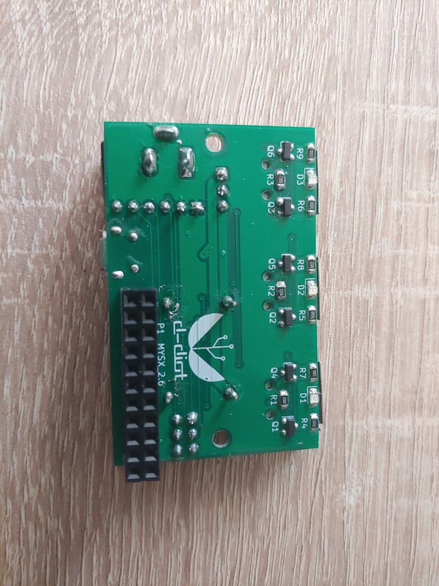
this is my last node. A 3d printable smart USB power hub.
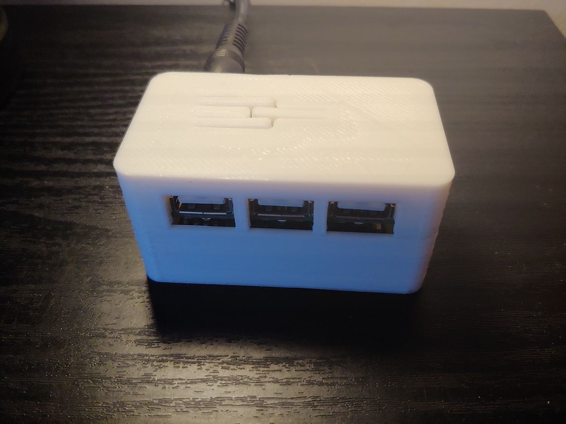
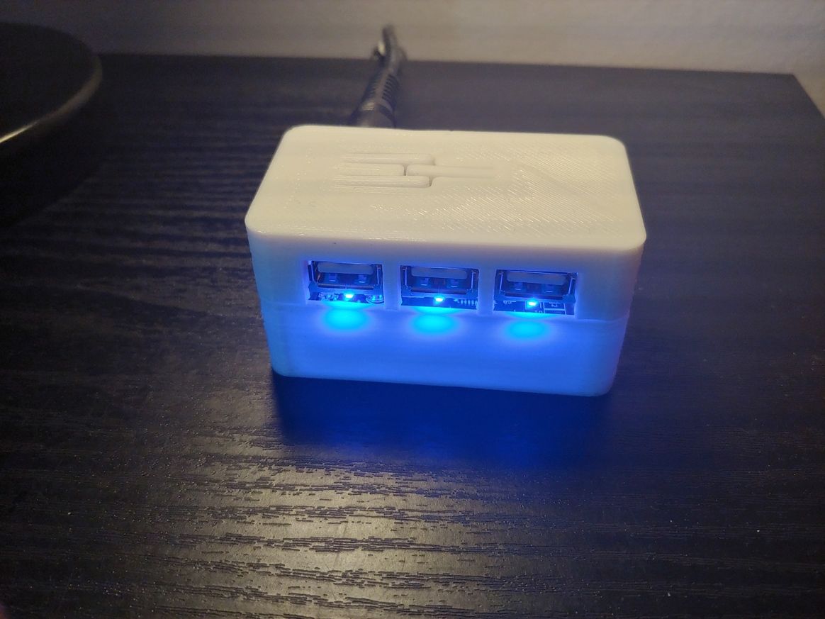
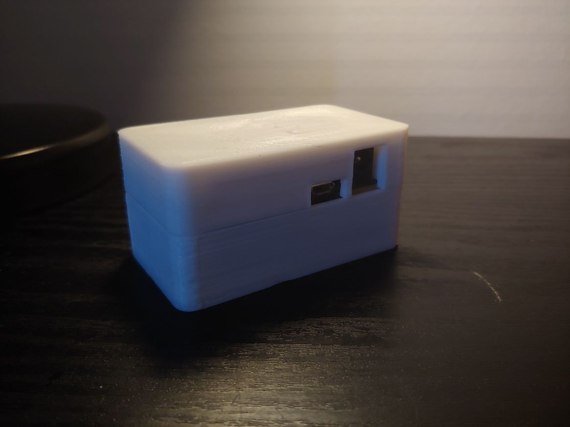
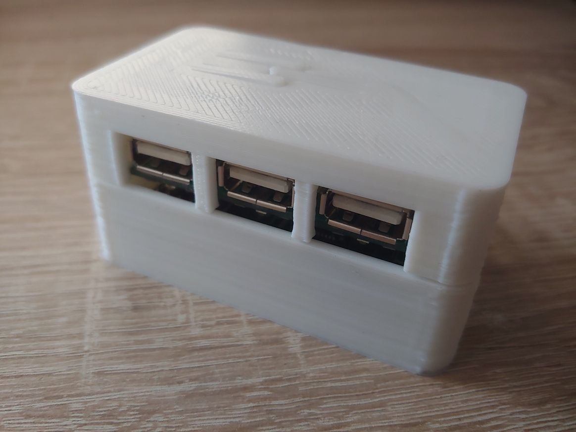
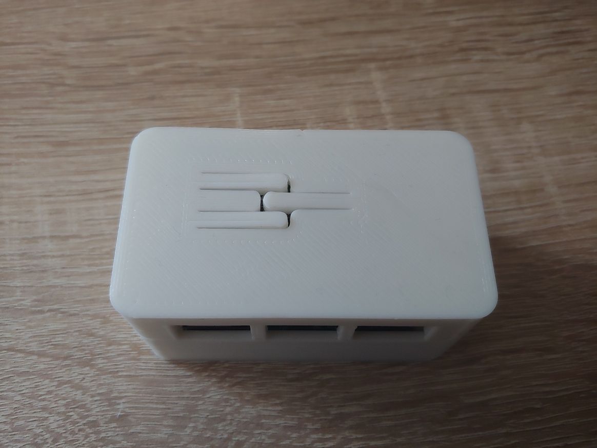
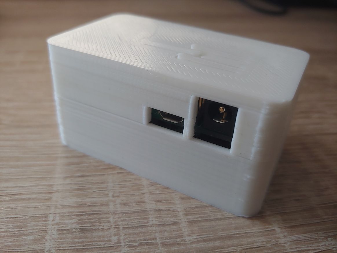
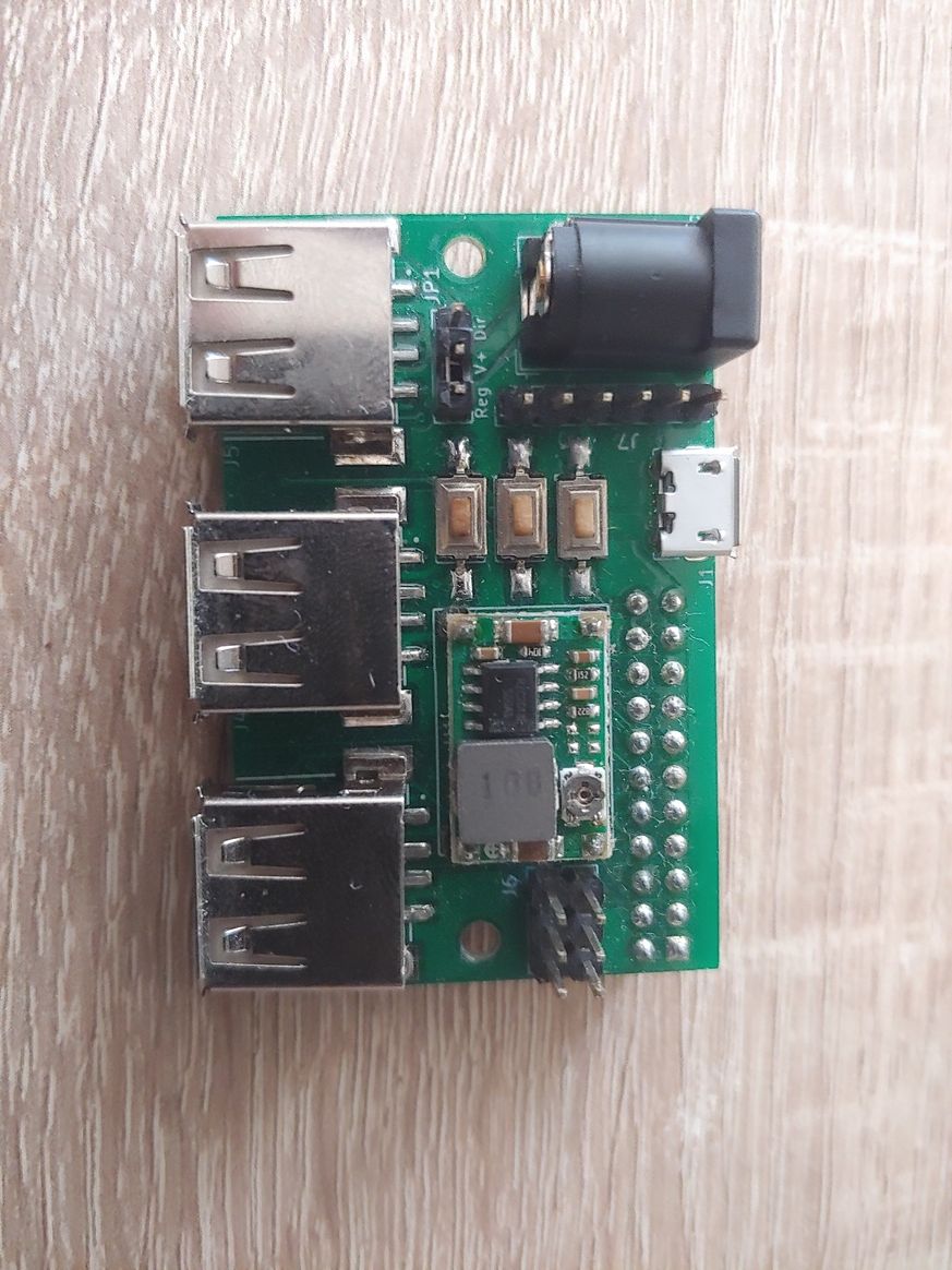
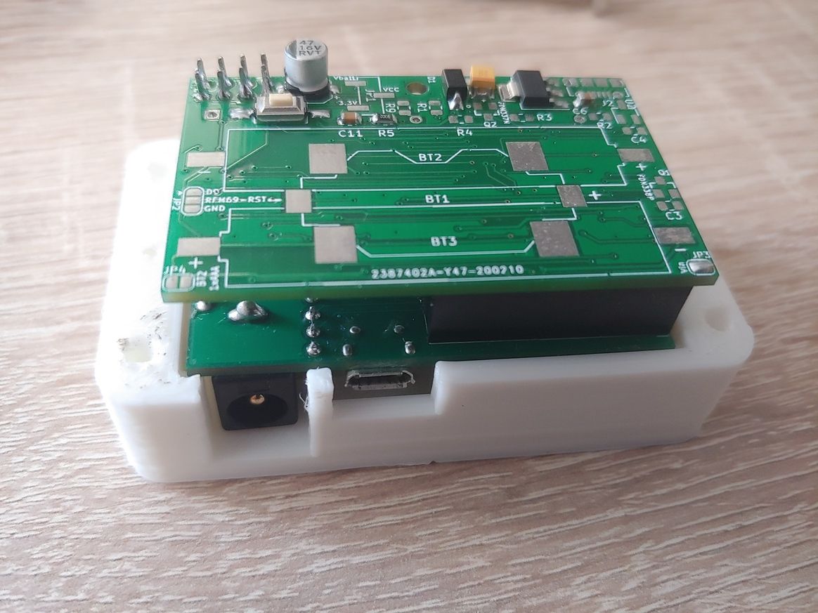
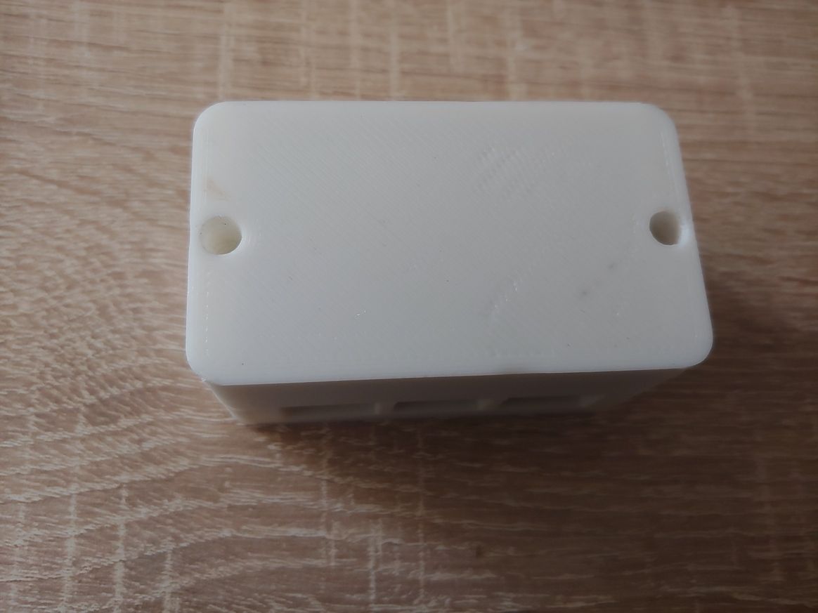
If someone is interested, here all the details.
-
I am testing a node with a DigiPyro, PYD 1598 motion detector. It is advertised to be low power and runs from 1.8 to 3.6 volts, so should run well with a coin cell. They have to be programmed with several options and I have not found a lot of documentation. I went with what seemed like the most sensitive choices and it seems to work so far. More research needed . ...
https://www.excelitas.com/product/pyd-1588-pyd-1598-low-power-digipyrosI bought a couple of these from DigiKey for around $4 each. Now they are more than $12 each and there is no stock. So, these may not be as good a choice as they seemed at first. We'll see . ...
-
The milling topic got my interest and I have been working on getting a machine for myself.
So far I have just assembled the machine and realised milling is a bit more difficult to start then 3d printing.
anyway, I would like to share my progress. I am building video's now :)No circuitsboards yet, but here is a introduction of my way to victory.
Unboxing the Genmitsu Prover 3018 cnc mill from sainsmart – 03:09
— Joeri de Man -
Winter time is tinker time!
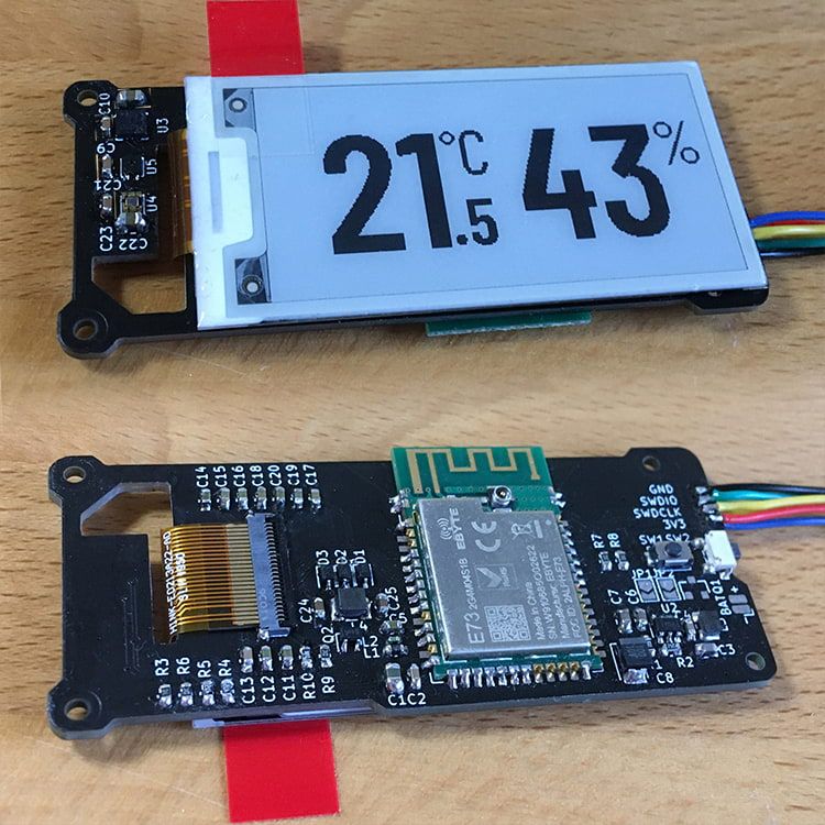
This is a compact environmental sensor node with an E-Paper display. My goal was to have a decent screen-to-body ratio with a simple and minimalistic display, easy to read from a distance. It is the first design in which I did not use an ATmega MCU. It is also the first time that I used KiCAD instead of EAGLE, soldered no-lead SMD components and worked with an EPD.
- It features a SHTC3 sensor to measure temperature and relative humidity and a VEML6030 to measure the ambient light, so that I can toggle lights or other appliances in the room based on temperature, humidity or light conditions.
- I have also added a MEMS sensor (LIS3DH) to auto-detect the device orientation and rotate the EPD image accordingly and / or detect tap events to toggle between different display modes / data sets.
- It can be powered directly from a 3V source or use the optional 3.3V boost circuit which accepts 1.5V or 3V sources.
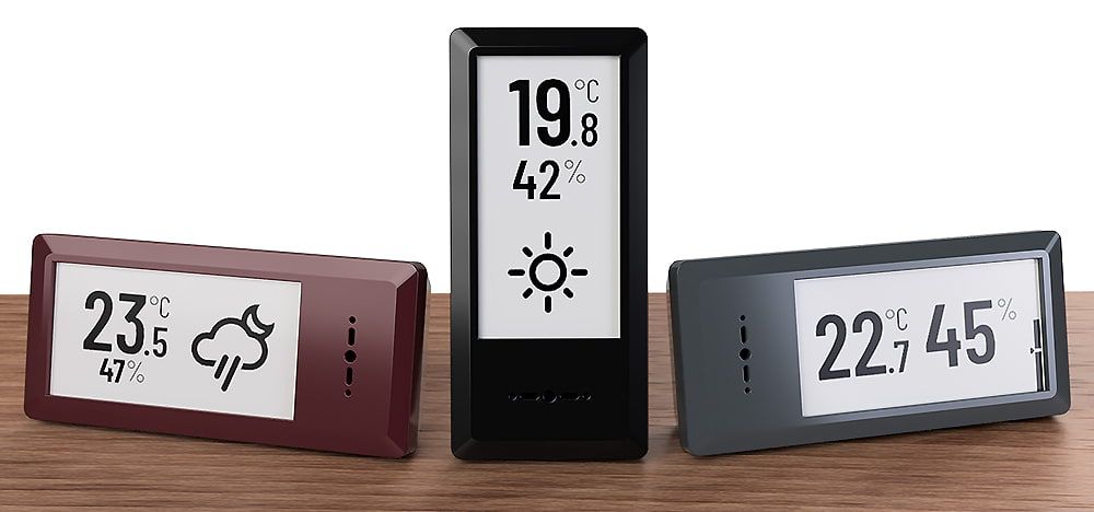
I finished soldering and testing all the components today and just started programming the rough "framework". Looks promising so far! But still lots to do, including finalizing the 3D printed enclosure. This is how it is supposed to look in the end:
-
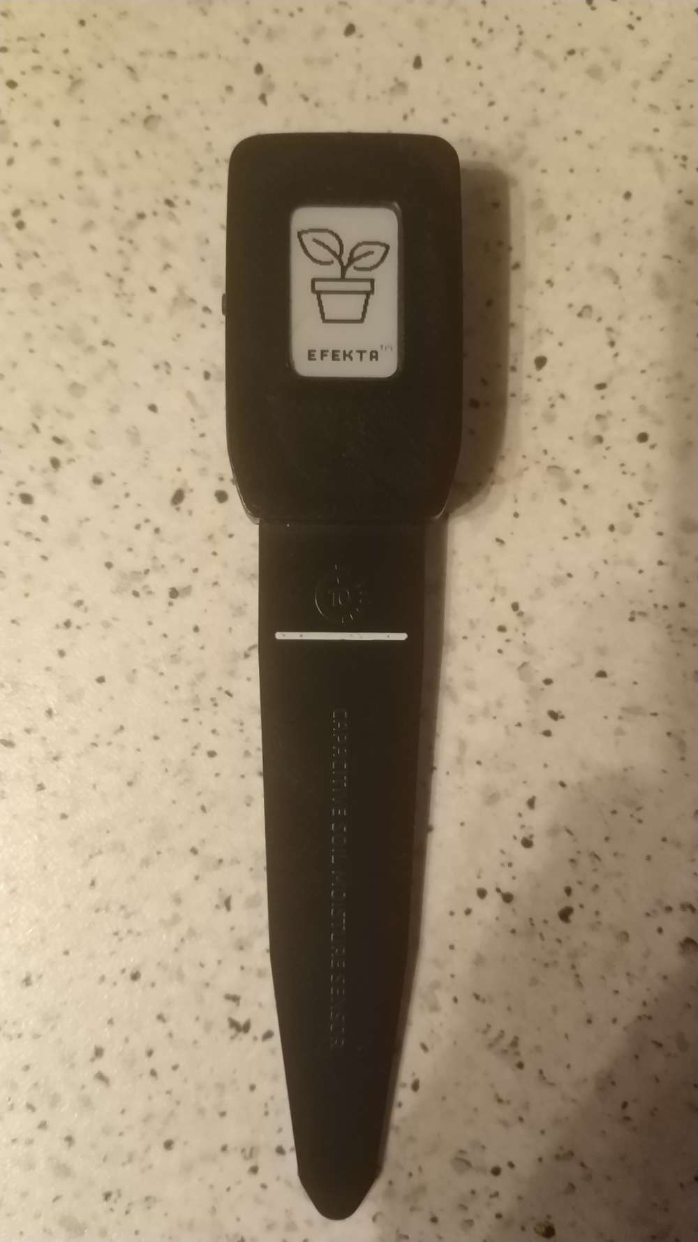
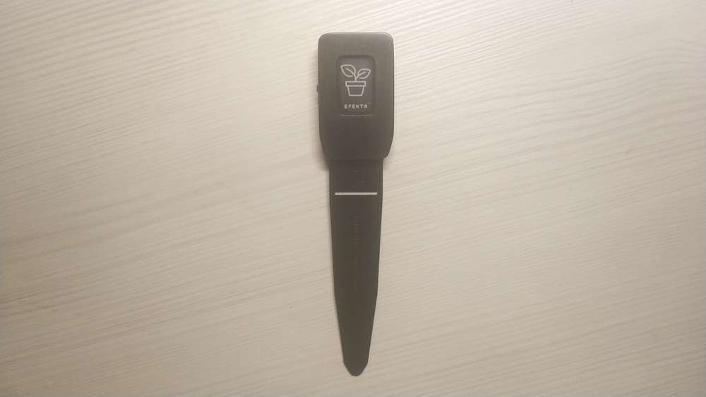
Hi guys. I recently made a plant watering control sensor with an electronic paper display. Today I did my first tests, ..everything went well :)
-
Winter time is tinker time!
This is a compact environmental sensor node with an E-Paper display. My goal was to have a decent screen-to-body ratio with a simple and minimalistic display, easy to read from a distance. It is the first design in which I did not use an ATmega MCU. It is also the first time that I used KiCAD instead of EAGLE, soldered no-lead SMD components and worked with an EPD.
- It features a SHTC3 sensor to measure temperature and relative humidity and a VEML6030 to measure the ambient light, so that I can toggle lights or other appliances in the room based on temperature, humidity or light conditions.
- I have also added a MEMS sensor (LIS3DH) to auto-detect the device orientation and rotate the EPD image accordingly and / or detect tap events to toggle between different display modes / data sets.
- It can be powered directly from a 3V source or use the optional 3.3V boost circuit which accepts 1.5V or 3V sources.
I finished soldering and testing all the components today and just started programming the rough "framework". Looks promising so far! But still lots to do, including finalizing the 3D printed enclosure. This is how it is supposed to look in the end:
@BearWithBeard said in What did you build today (Pictures) ?:
VEML6030
Take a closer look at the max44009 light sensor and the lis2dw12 accelerometer. You can save a few microamps.
-
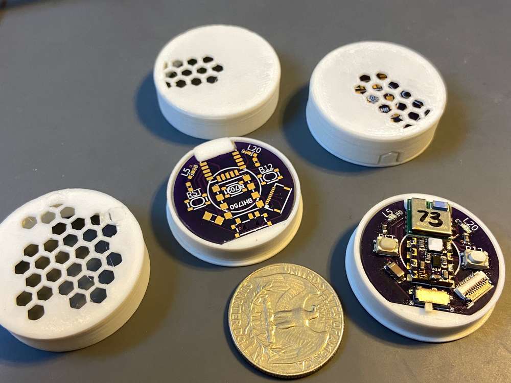
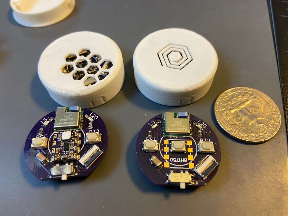
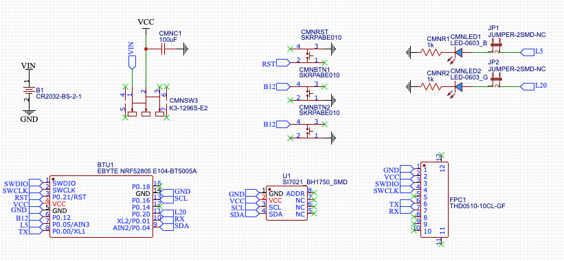
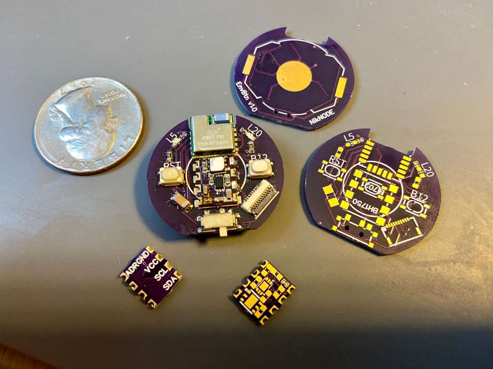
First attempt at a modular NRF52805 based board. The smaller board has a Si7021 temp + humidity sensor and a BH1750 light level sensor, both I2C. Ideally, I should be-able to make other sensor boards with the same footprint as long as the sensors are I2C.
Also included:
- CR2032 Battery (~1.5 years between battery changes)
- 10P 0.5 FPC connector for programming and serial debugging
- 2 LEDs with solderable jumpers
- On/Off switch (I find this really useful, especially when fighting with coin batteries)
- RST button
- Secondary button that I use to force immediate readings
- Footprint for centered button for alternative use as a remote button (my most common MySensors node)
I'll post pictures of the enclosure when it's ready.
I'm also waiting on delivery of a slightly larger version of this board that holds a 2477 battery and a SMD PIR motion sensor.
-
First attempt at a modular NRF52805 based board. The smaller board has a Si7021 temp + humidity sensor and a BH1750 light level sensor, both I2C. Ideally, I should be-able to make other sensor boards with the same footprint as long as the sensors are I2C.
Also included:
- CR2032 Battery (~1.5 years between battery changes)
- 10P 0.5 FPC connector for programming and serial debugging
- 2 LEDs with solderable jumpers
- On/Off switch (I find this really useful, especially when fighting with coin batteries)
- RST button
- Secondary button that I use to force immediate readings
- Footprint for centered button for alternative use as a remote button (my most common MySensors node)
I'll post pictures of the enclosure when it's ready.
I'm also waiting on delivery of a slightly larger version of this board that holds a 2477 battery and a SMD PIR motion sensor.
@ncollins
Very, very beautiful project! I also already have several such radio modules from different manufacturers. Here are just these ebyte specifically, they are without dc-dc. ...I plan to transfer support from nordic sdk to sandeep mistry (just like I did with 52810 and 52811), but how do you flash them under mysensors? Maybe there is already some shorter way? -
@ncollins
Very, very beautiful project! I also already have several such radio modules from different manufacturers. Here are just these ebyte specifically, they are without dc-dc. ...I plan to transfer support from nordic sdk to sandeep mistry (just like I did with 52810 and 52811), but how do you flash them under mysensors? Maybe there is already some shorter way?@berkseo Thank you!
First, I made the compatibility changes to SandeepMistry. This was surprisingly easy. The SDK in SandeepMistry/nRF5-arduino does most of the heavy lifting. I had to modify a few of the precompiler conditions to exclude PWM, change some serial definitions, and update to new handler naming conventions: https://github.com/sandeepmistry/arduino-nRF5/pull/442
Then, I defined a new Generic NRF52805 variant in mysensors/ArduinoHwNRF5 and handled one assumption of LPCOMP: https://github.com/mysensors/ArduinoHwNRF5/pull/12
Last, I had to handle a few small assumptions in the MySensors library: https://github.com/mysensors/MySensors/pull/1461
-
Winter time is tinker time!
This is a compact environmental sensor node with an E-Paper display. My goal was to have a decent screen-to-body ratio with a simple and minimalistic display, easy to read from a distance. It is the first design in which I did not use an ATmega MCU. It is also the first time that I used KiCAD instead of EAGLE, soldered no-lead SMD components and worked with an EPD.
- It features a SHTC3 sensor to measure temperature and relative humidity and a VEML6030 to measure the ambient light, so that I can toggle lights or other appliances in the room based on temperature, humidity or light conditions.
- I have also added a MEMS sensor (LIS3DH) to auto-detect the device orientation and rotate the EPD image accordingly and / or detect tap events to toggle between different display modes / data sets.
- It can be powered directly from a 3V source or use the optional 3.3V boost circuit which accepts 1.5V or 3V sources.
I finished soldering and testing all the components today and just started programming the rough "framework". Looks promising so far! But still lots to do, including finalizing the 3D printed enclosure. This is how it is supposed to look in the end:
@BearWithBeard Very nice indeed!
-
First attempt at a modular NRF52805 based board. The smaller board has a Si7021 temp + humidity sensor and a BH1750 light level sensor, both I2C. Ideally, I should be-able to make other sensor boards with the same footprint as long as the sensors are I2C.
Also included:
- CR2032 Battery (~1.5 years between battery changes)
- 10P 0.5 FPC connector for programming and serial debugging
- 2 LEDs with solderable jumpers
- On/Off switch (I find this really useful, especially when fighting with coin batteries)
- RST button
- Secondary button that I use to force immediate readings
- Footprint for centered button for alternative use as a remote button (my most common MySensors node)
I'll post pictures of the enclosure when it's ready.
I'm also waiting on delivery of a slightly larger version of this board that holds a 2477 battery and a SMD PIR motion sensor.
@ncollins said in What did you build today (Pictures) ?:
10P 0.5 FPC connector for programming and serial debugging
How many of the 10 pins do you actually use?
-
@ncollins said in What did you build today (Pictures) ?:
10P 0.5 FPC connector for programming and serial debugging
How many of the 10 pins do you actually use?
-
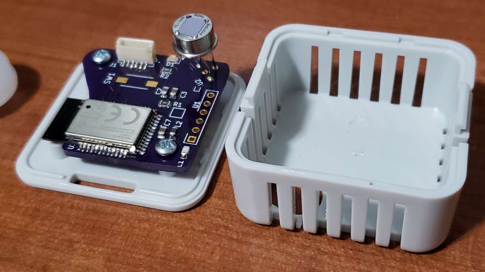
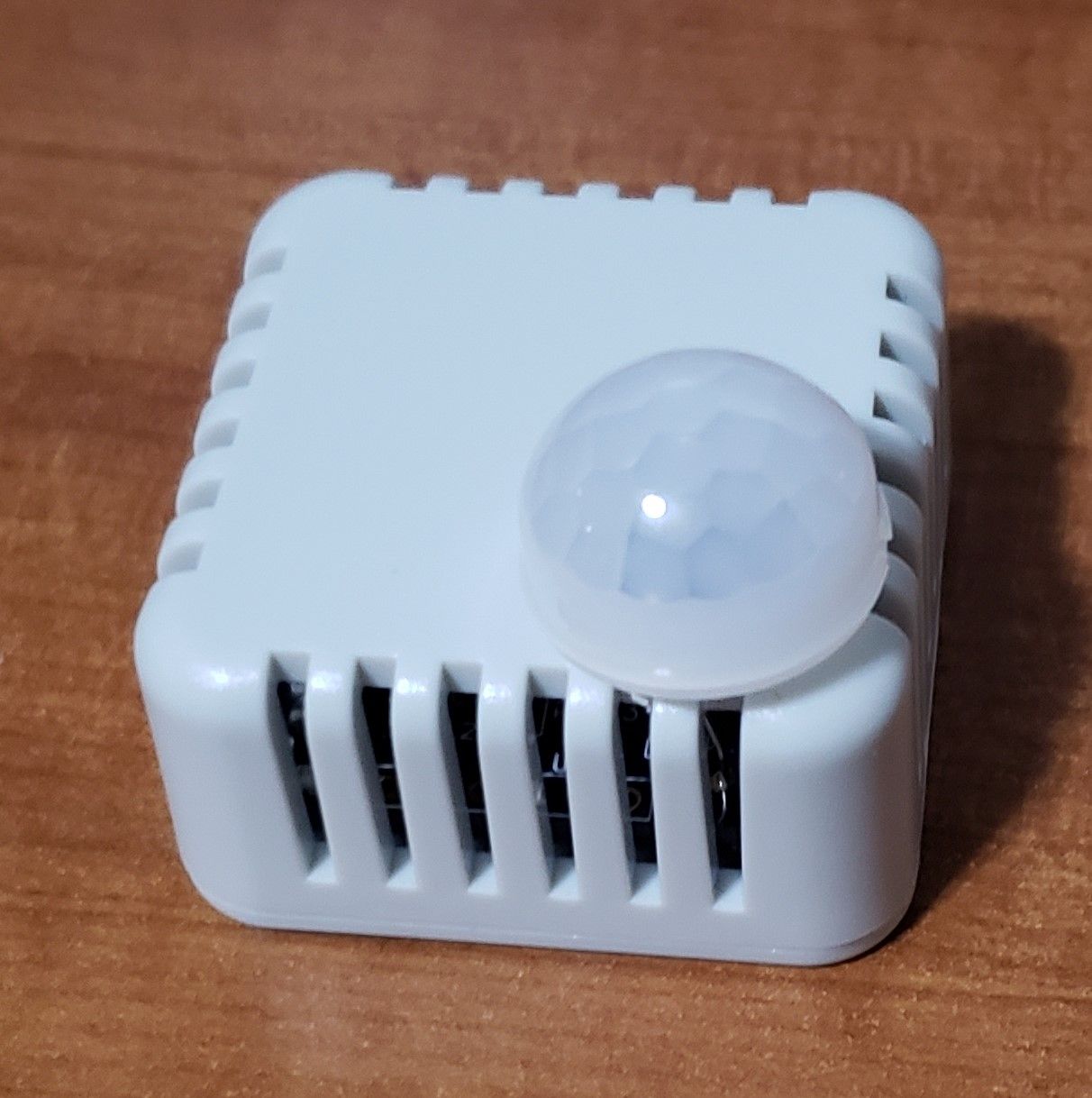
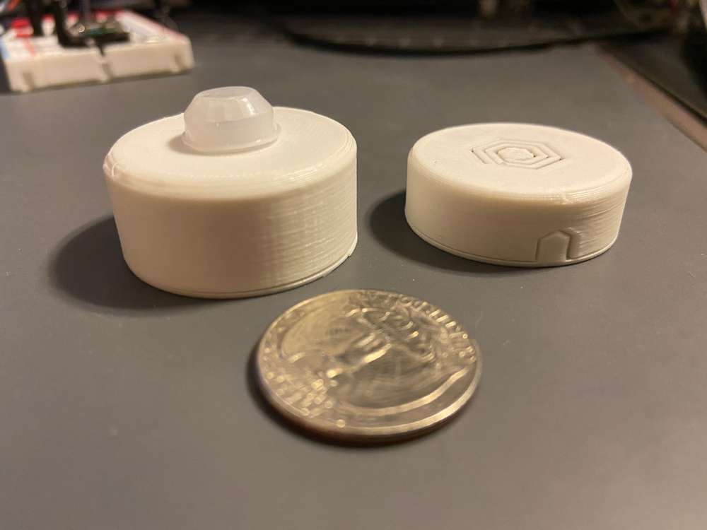
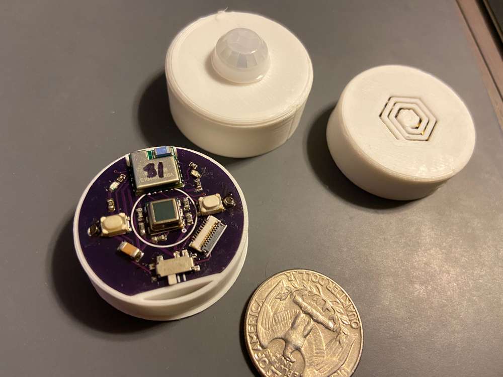
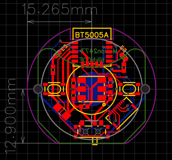
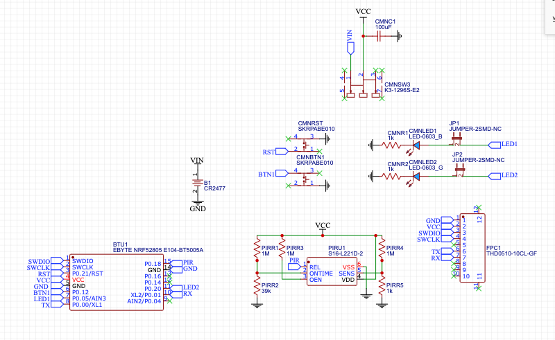
The latest addition to my coin cell nodes, a PIR motion sensor based on the Ebyte NRF52805 module.
The PIR sensor is a Senba S16-L221D-2. I'm measuring around 24uA, which is higher than advertised, but with the 6-7uA from the NRF52805, should still get me 3-4 years on a single 2477.
-
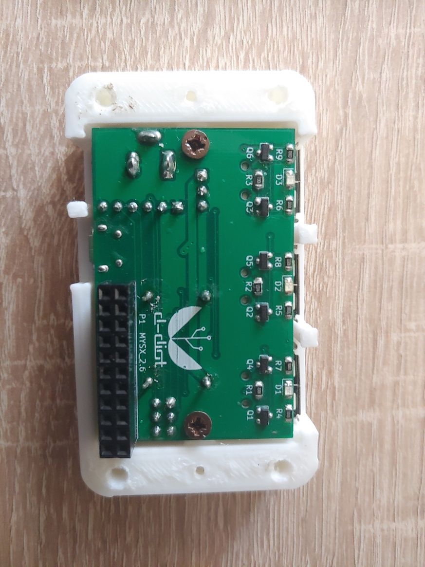
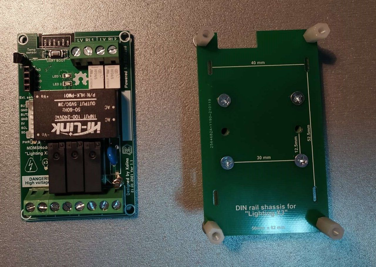
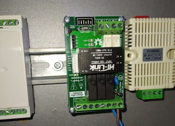
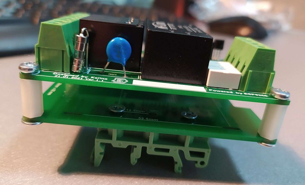
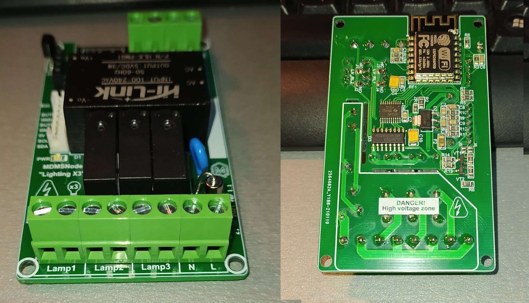
Today i have assembled the latest revision of my Lighting X3 for DIN rail mounting.
-
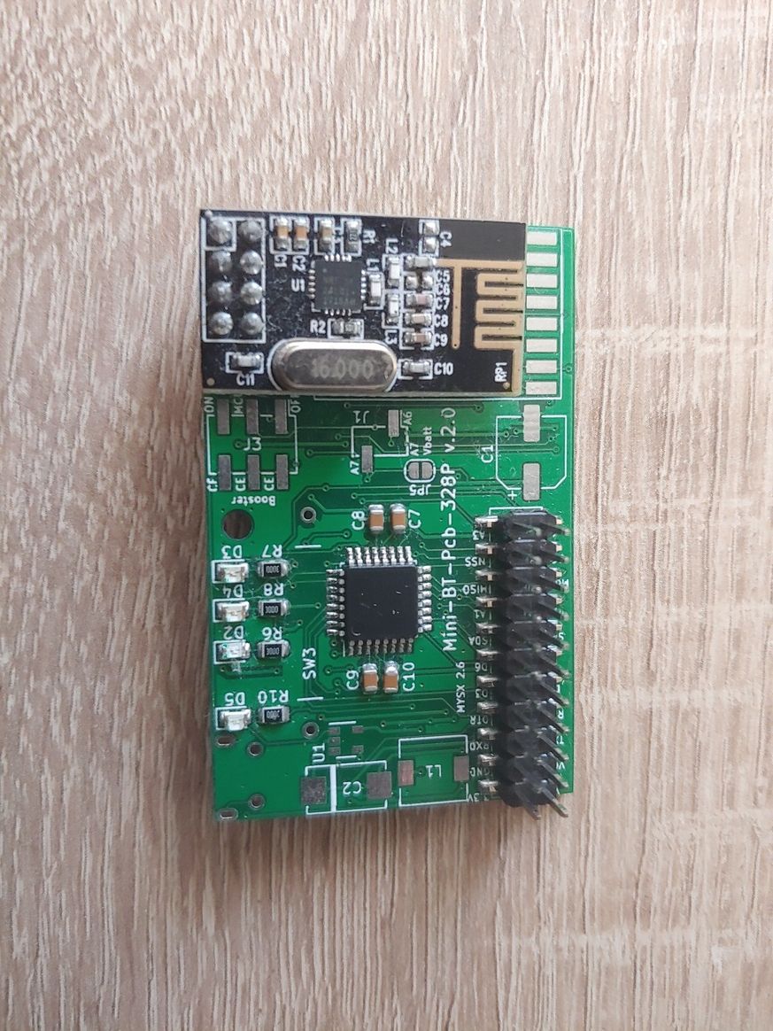
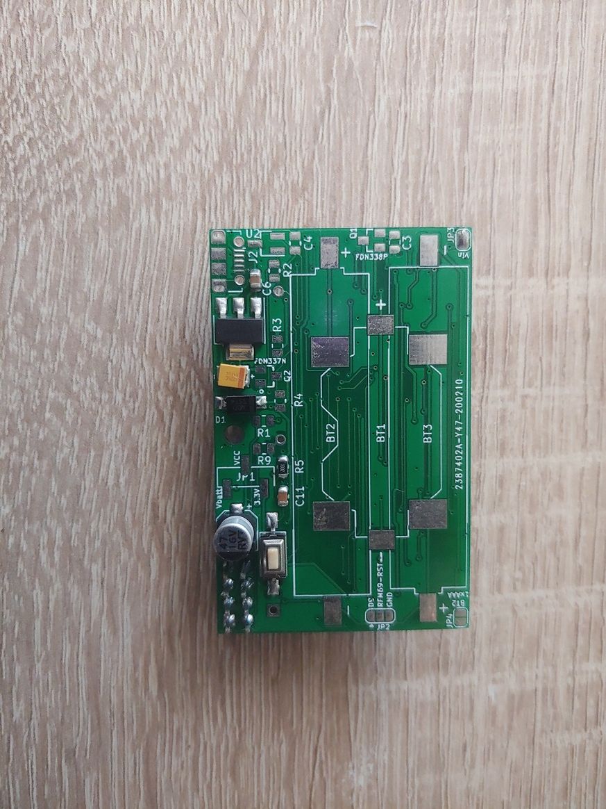
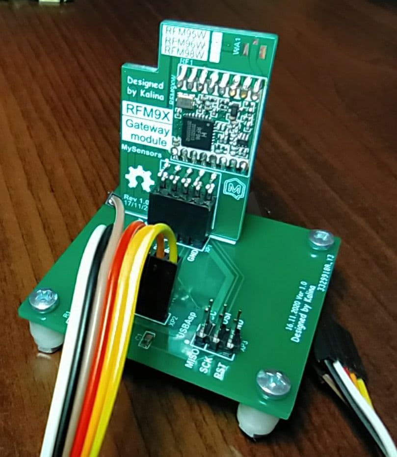
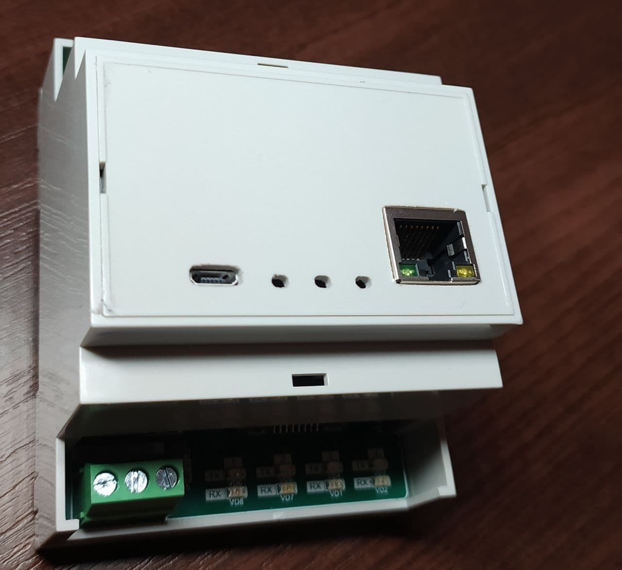
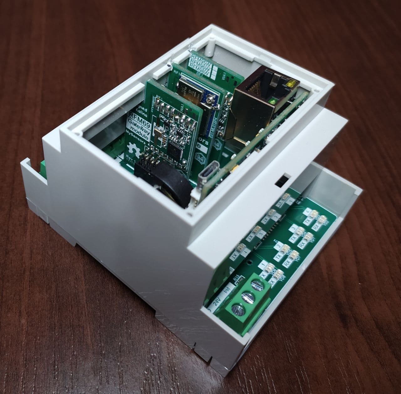
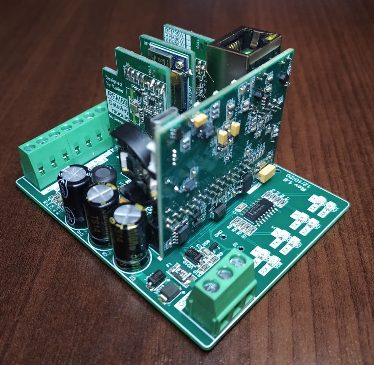
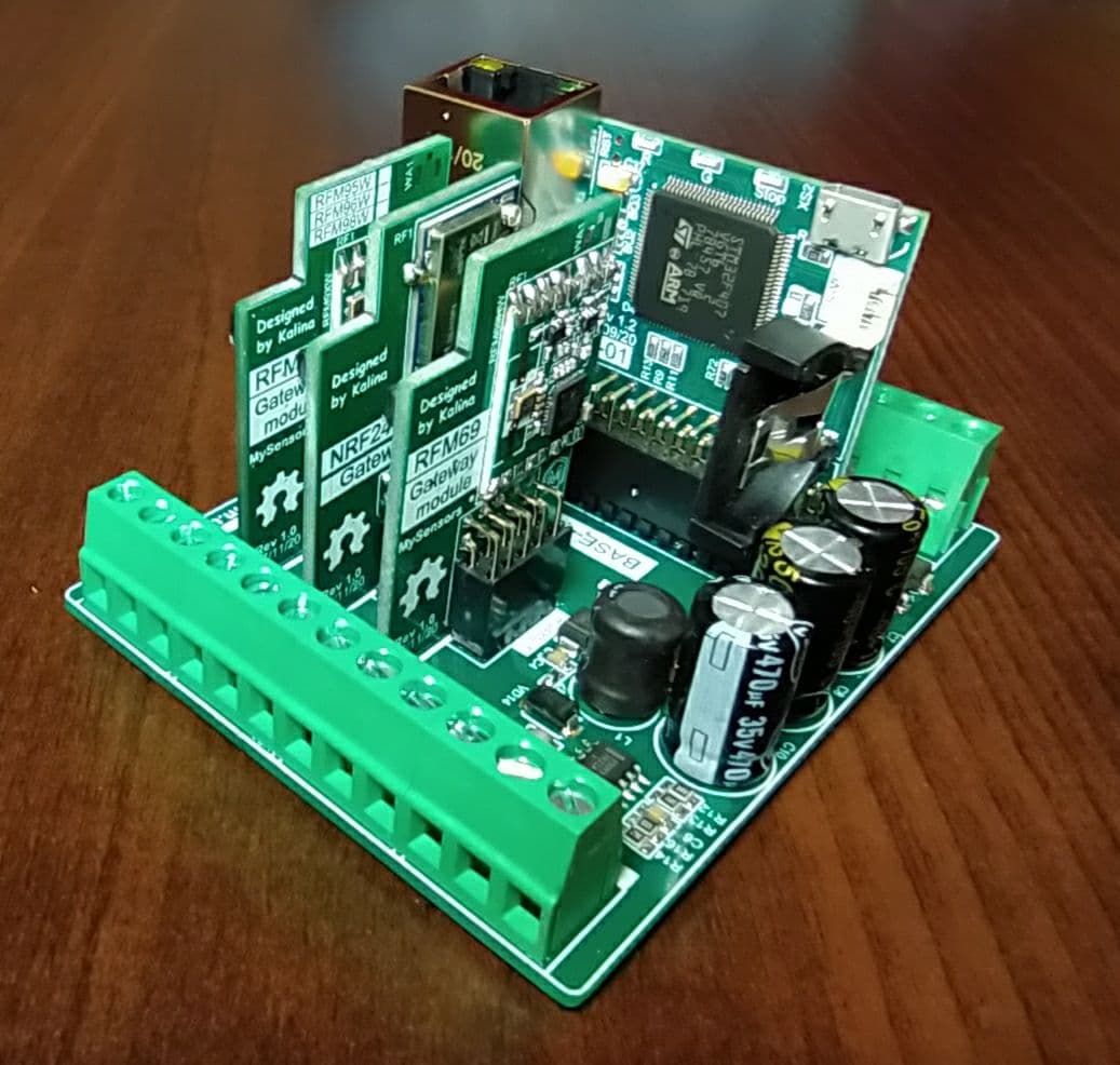
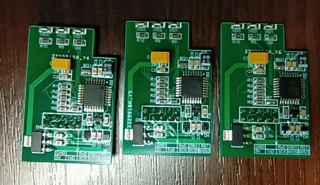
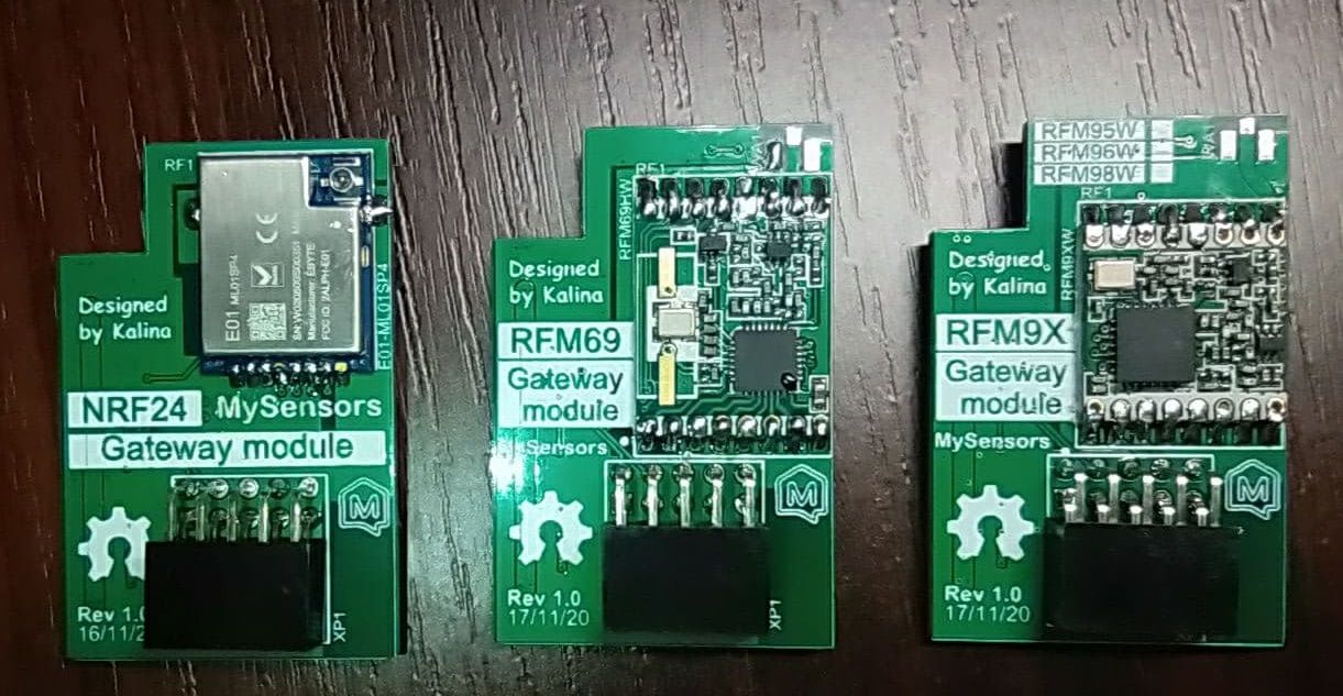
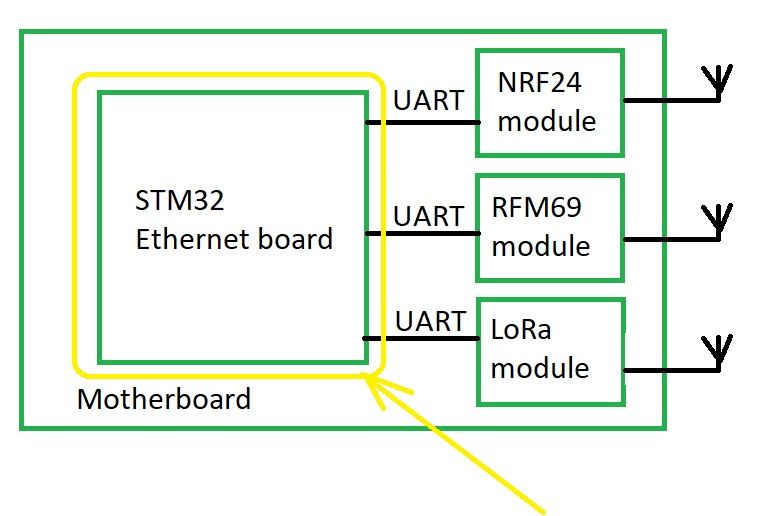
Oh yes, I forgot to share photos of my new project - Multinetwork Mysensors Gateway. The main idea of this gateway is that it can at the same time serve up to four different networks (Lora - RFM9X, 2.4 GHz - NRF24 and ISM band RFM69). These networks can be assembled in separate modules and each user can build own set of modules. The incoming stream will be connected via Ethernet on various ports, for example, the gate will have the IP address 192.168.1.128, and each subnet will be served on ports 5003 - the first subnet, 5004 - the second, and so on ...
-
@monte Not certainly in that way. In this project, everything is open source with the exception of the board with an ethernet (based on STM32). The ethernet board was developed by my partners and they are not ready to share it yet. But I hope I can persuade them to do it :-)
-
@monte Not certainly in that way. In this project, everything is open source with the exception of the board with an ethernet (based on STM32). The ethernet board was developed by my partners and they are not ready to share it yet. But I hope I can persuade them to do it :-)
@kalina I like how it both consolidates and reduces wall-wart clutter all in one stroke. :-)
I don't see any antennas though. Where do they go? And does having multiple radios packed close together like that create any noteworthy EMI? I knew a guy who had set up an RFM69 hat on his Raspberry Pi but later found that the raspberry Pi produced a lot of RF noise/EMI that reduced the effective range of his gateway. I don't know whether or not that might happen in your case, but I thought I'd mention it to help with your troubleshooting in the event you notice any unexpected range reduction.