What did you build today (Pictures) ?

-
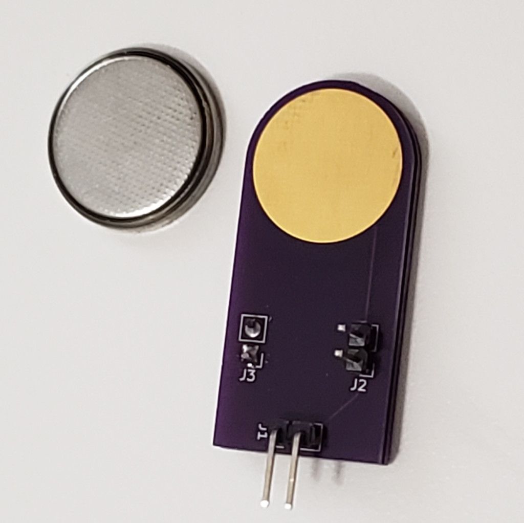
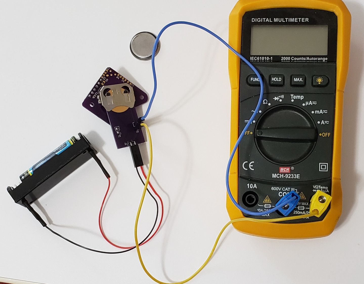
I made a simple board to use as a CR2032 battery simulator. It is actually two identical pcb's back to back. I added pins for applying power and another set for measuring current. Now I need a better ammeter. The uA scale works well when sleeping, but the mA scale doesn't seem to pick up the awake current.
-
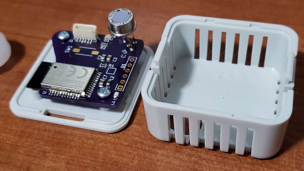
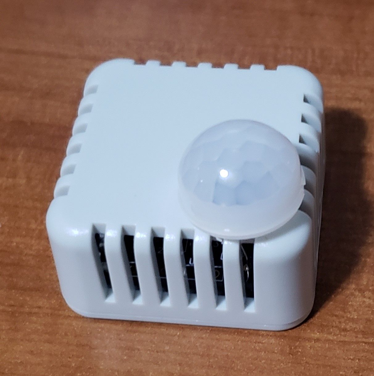
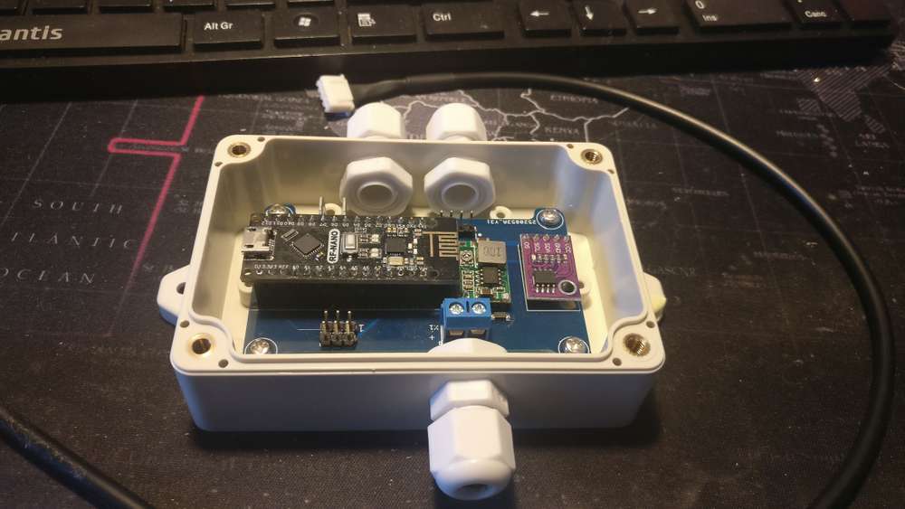
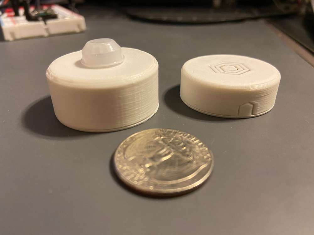
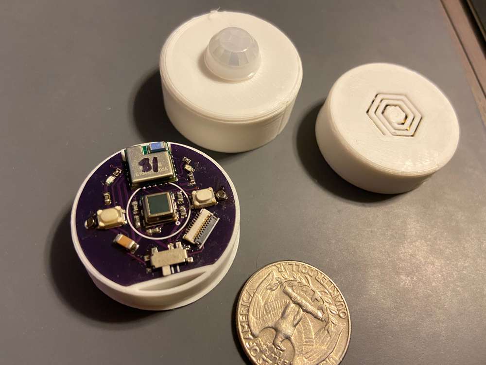
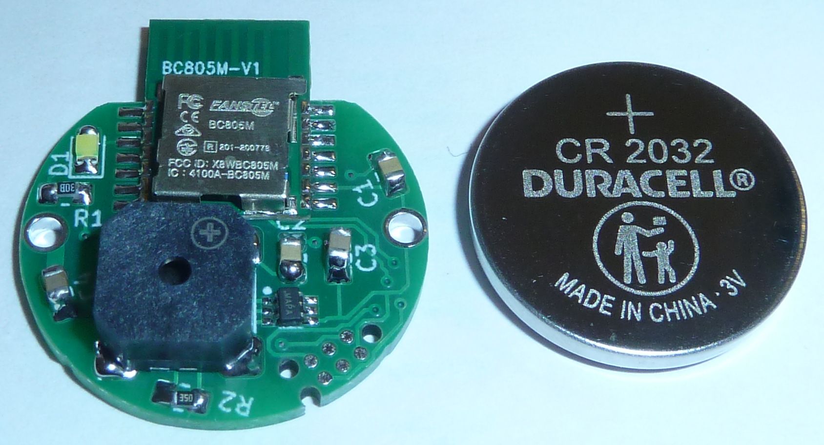
I am testing a node with a DigiPyro, PYD 1598 motion detector. It is advertised to be low power and runs from 1.8 to 3.6 volts, so should run well with a coin cell. They have to be programmed with several options and I have not found a lot of documentation. I went with what seemed like the most sensitive choices and it seems to work so far. More research needed . ...
https://www.excelitas.com/product/pyd-1588-pyd-1598-low-power-digipyrosI bought a couple of these from DigiKey for around $4 each. Now they are more than $12 each and there is no stock. So, these may not be as good a choice as they seemed at first. We'll see . ...
It's actually at this link posted earlier in the thread: What did you build today (Pictures) ?:
I mostly use it with BME280 modules for temperature and humidity, but I have tried some other I2C modules in it.
I'm still experimenting with the motion detector. That will probably get it's own board at some point. It doesn't really fit the enclosure I designed this board for. -
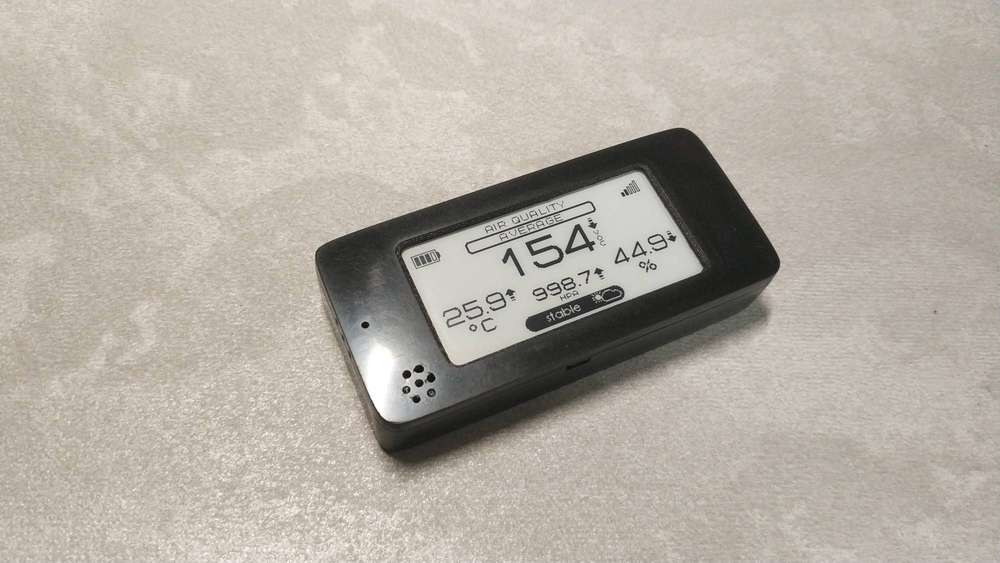
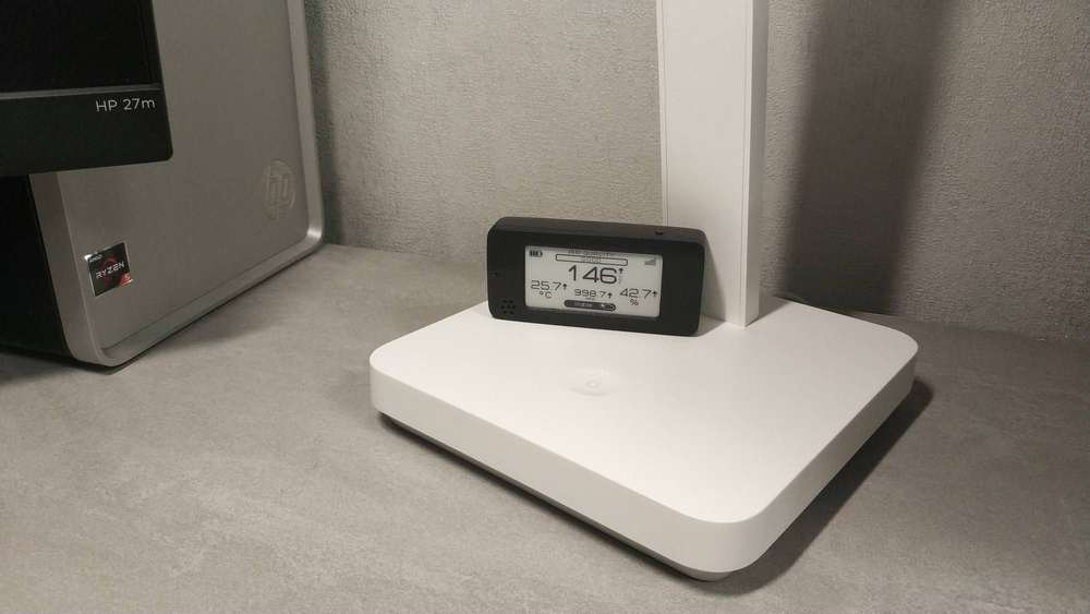
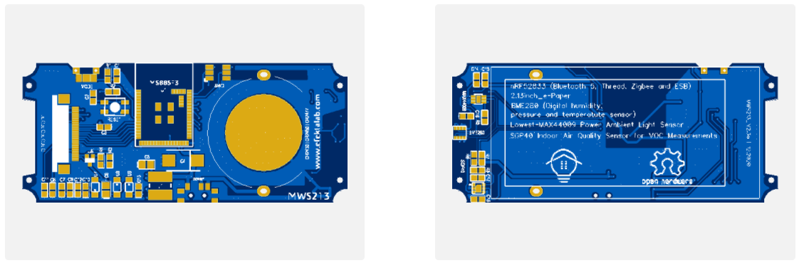
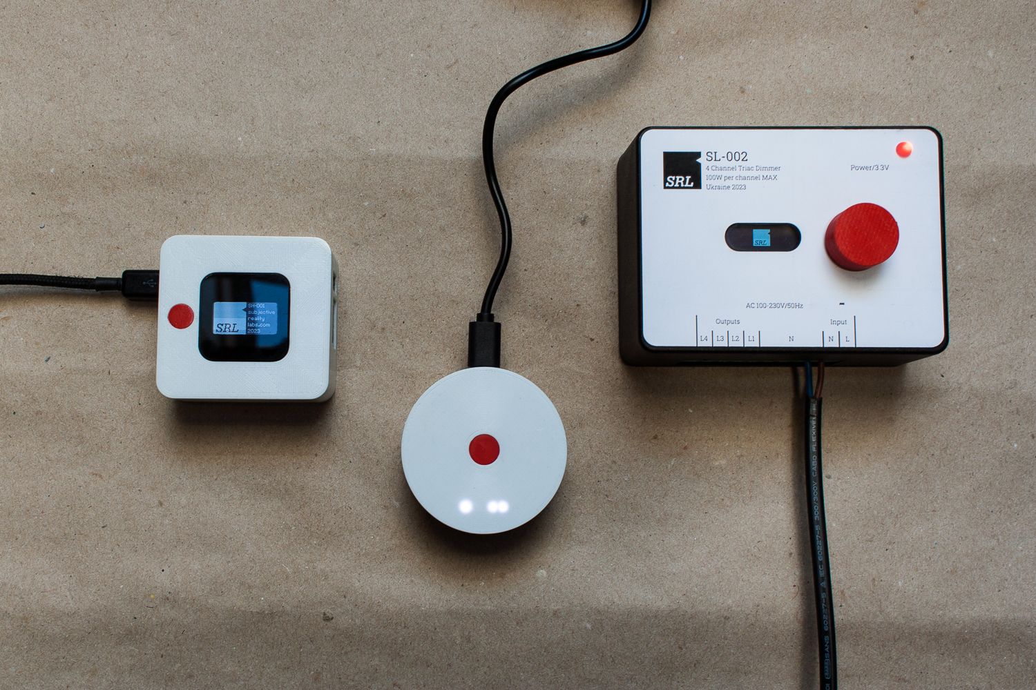
I think this open source project is finished. This is a small air quality sensor. Quite a useful thing turned out for our not simple time.
https://github.com/smartboxchannel/EFEKTA-EINK213-AIR-QUALITY-SENSOR-NRF52840-V2-ED3
-
Finished my Garage Door Node.
It has open/close magnetic reed switch sensors, a DS18B20 temperature sensor, a PIR motion sensor and a bjt to trigger the door to open/close/stop. -
Finished my Garage Door Node.
It has open/close magnetic reed switch sensors, a DS18B20 temperature sensor, a PIR motion sensor and a bjt to trigger the door to open/close/stop. -
Thanks.
The motion sensor is used to turn on the lights in the garage via a Sonoff mini.
Also, I've had the garage door randomly open by itself (power glitches?) a few times over the years. So I'm adding an automation to close the door if no motion is present and it is after midnight. -
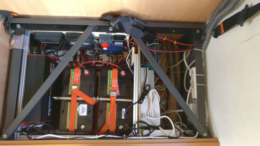
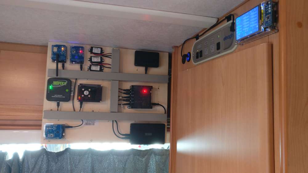
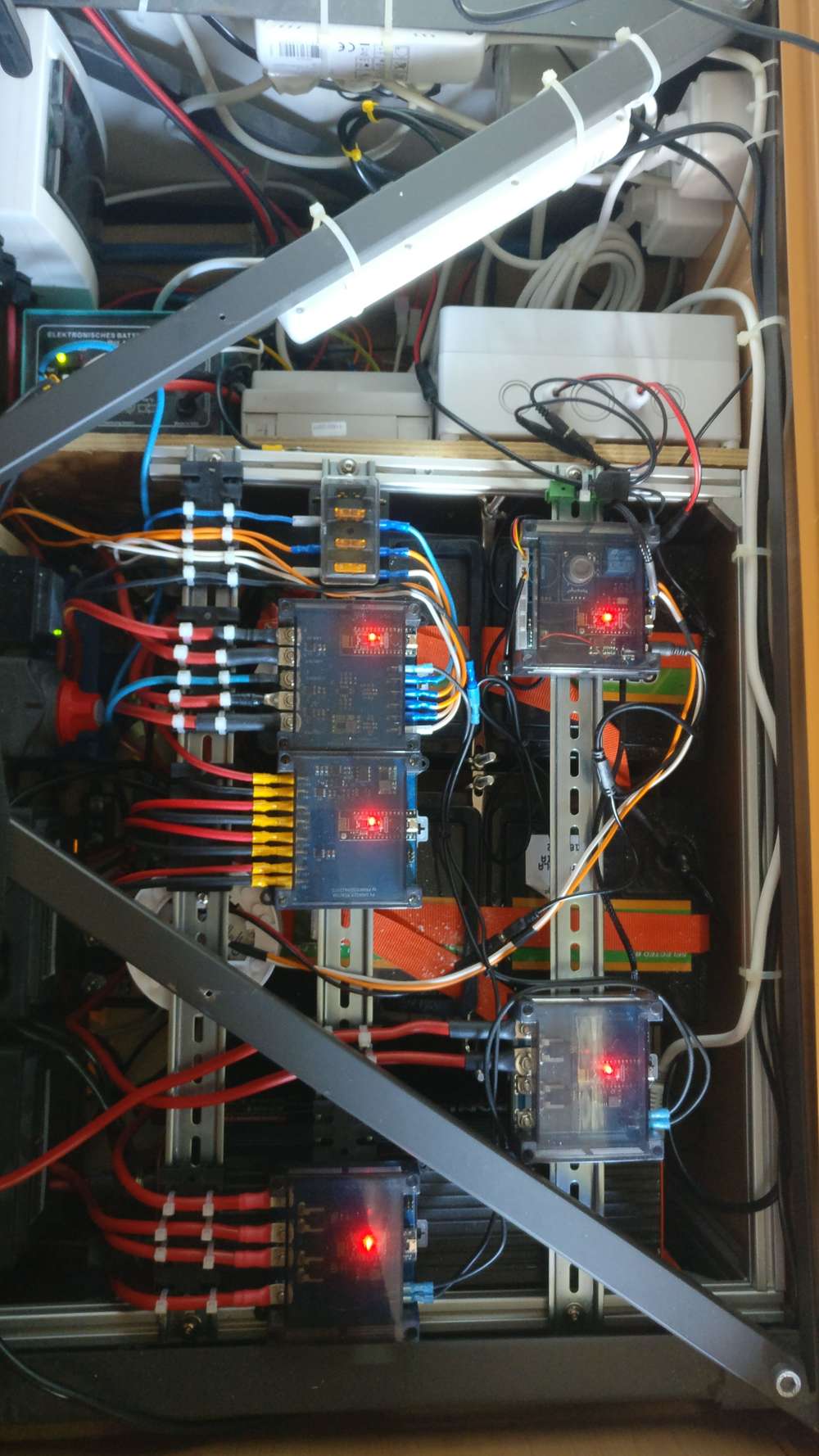
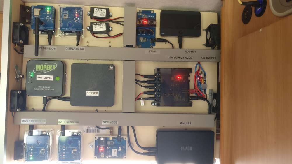
A collection of the sensors and actuators I buit for my camper in the past year
the power supply system under the dinette seat
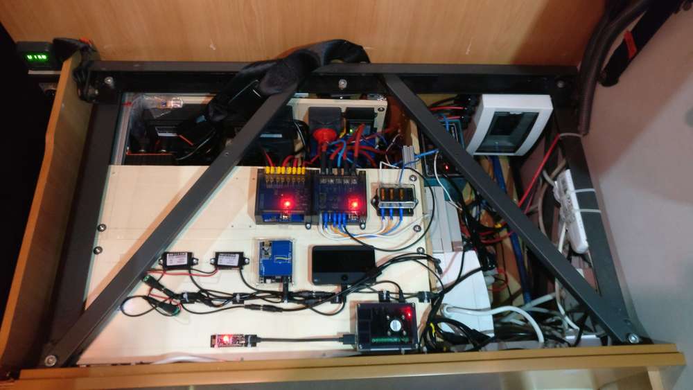
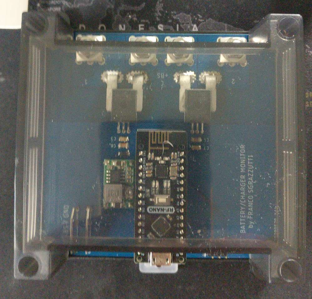
the battery management system (purchased) data are read via wifi by an ESP32, which reports the info to the GW via nRF24L01+.a closed look at 2 sensors.
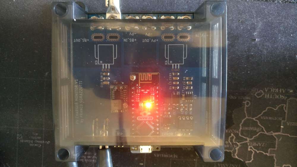
the one on the left reads voltage and current from the solar PV panel and to the battery management system
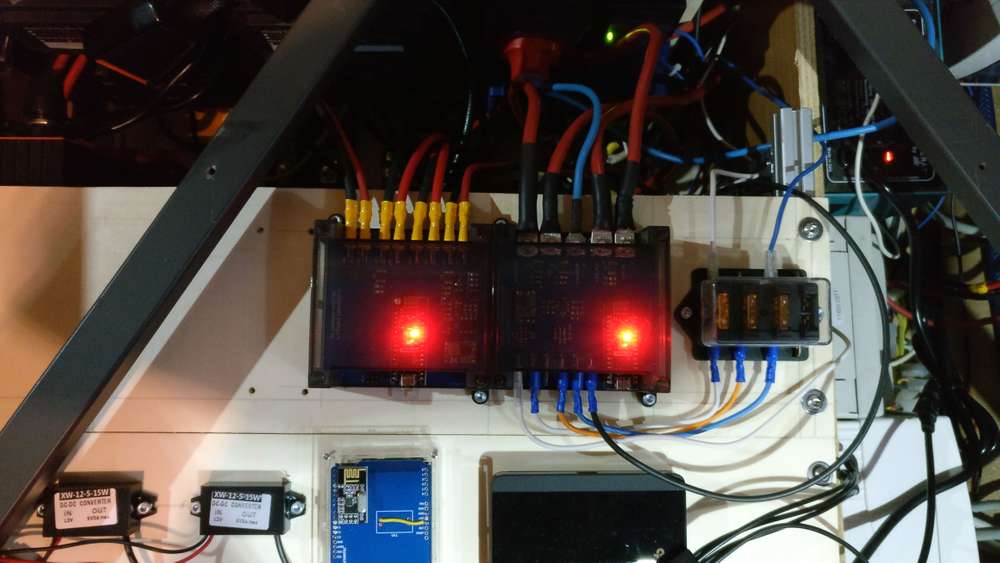
the one on the right reads voltage and current from/to the start and service batteriers
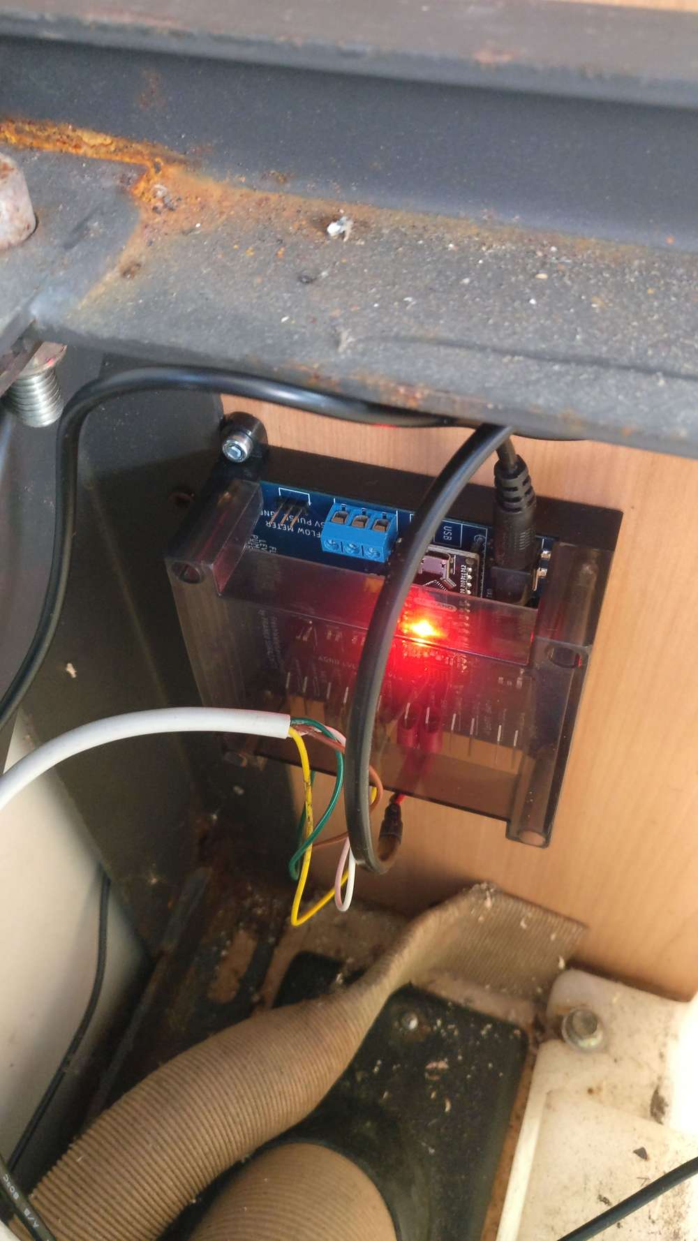
both sensors report instant power and energy.Fresh water sensor reads the water level, flow and temperature.
has 4 optcoupled outputs to send the information to the 4 LEDs of the original control panel of the camper
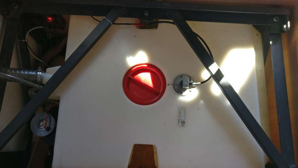
gray water tank sensor reports water level with an ultrasound sensor. has an optocoupled output to the "full" LED of the original control panel
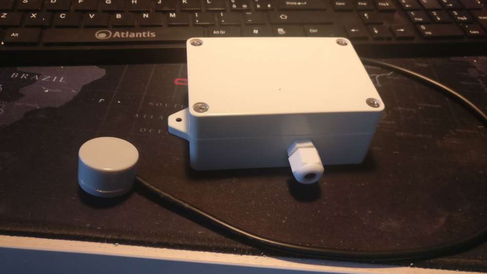
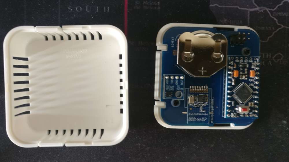
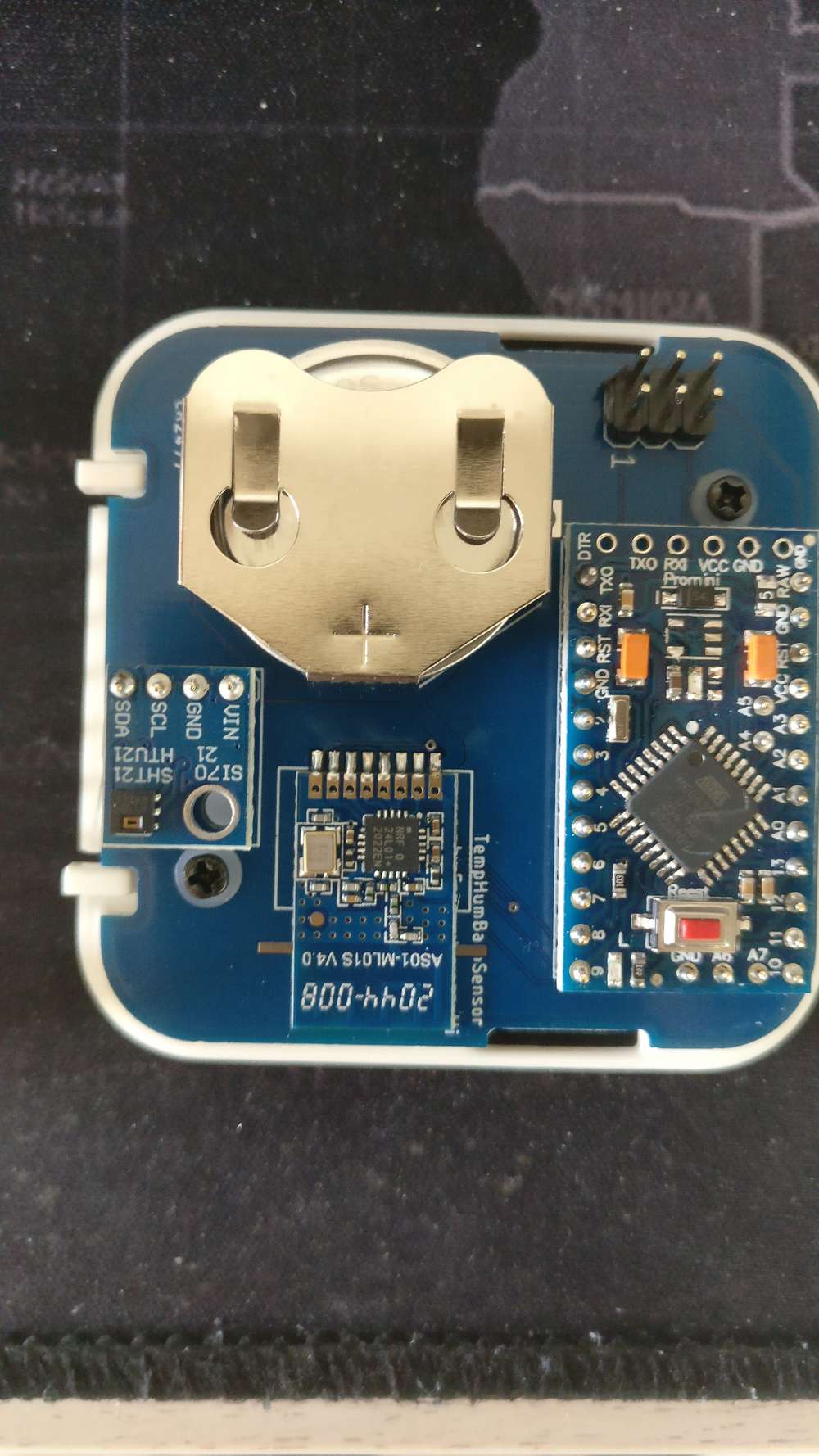
bettry supplied temperature and humidity sensor.
I use it in the fridge but also at home, where I have also one with BME280.
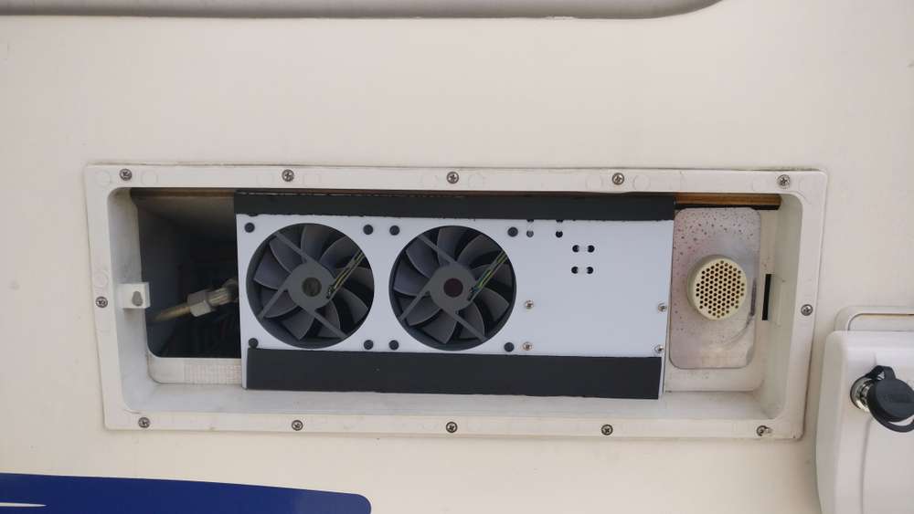
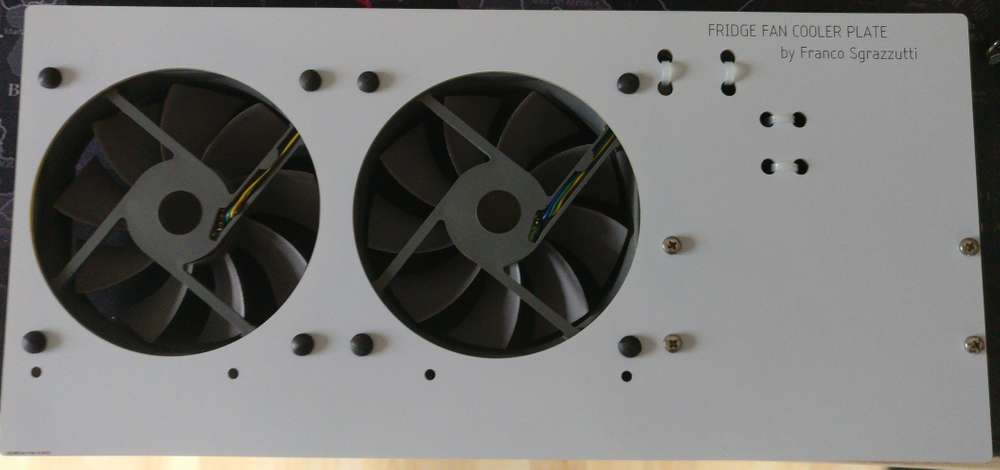
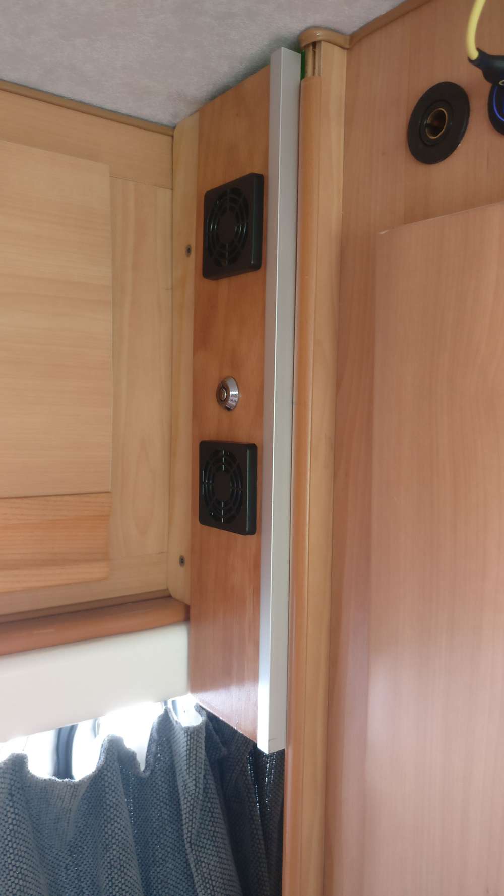
A fan controller to help the fridge to work better, controlling the condenser temperature using an optical thermometer sensor.
I have 3 other units, one in the power supply system, one in the closet and one on the roof.
They are all with a PID controller.

-
This thread is really good, kind of addicting to scroll all time.
Only problem though is the way it is structured. Its really hard to find the same post twice.Maybe the admins should consider having a separate section for this !!>?
-
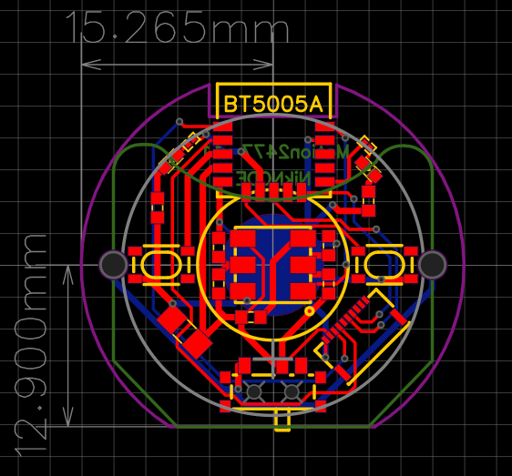
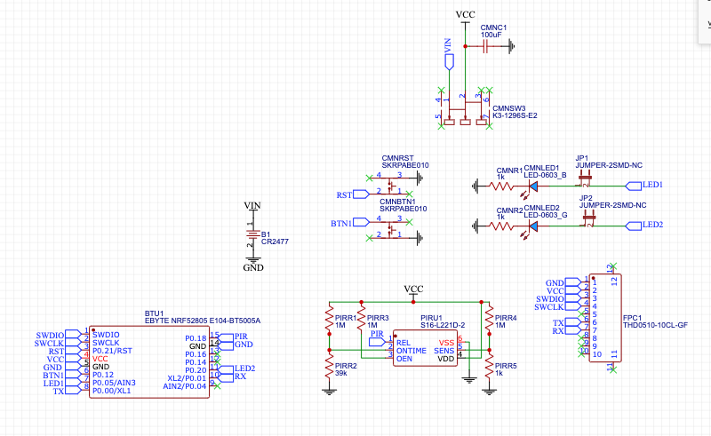
The latest addition to my coin cell nodes, a PIR motion sensor based on the Ebyte NRF52805 module.
The PIR sensor is a Senba S16-L221D-2. I'm measuring around 24uA, which is higher than advertised, but with the 6-7uA from the NRF52805, should still get me 3-4 years on a single 2477.
@ncollins said in What did you build today (Pictures) ?:
Ebyte NRF52805 module
Hi, I see you integrated the E104-BT5005A BLE chip in this project.
I’m trying to use it in a simple robot project and having difficulties to make the RX/TX connection with “RF Connect” IOS app.
I already wired the chip to the Seeeduino board and I can find and connect the bluetooth on the RF scan list. But I just don’t know the Arduino code to make it send and receive simple massages on the Arduino serial monitor.Your help is very much appreciated.
Amit
-
Some updates in almost one year.
I moved all the gateways and controller part in a most suitable location
I've created a dual current sensor for the fuse box and the inverter. Each Current sensors can withstand 90A max, so I used both channels in parallel. The sensors are defined for both Channel 1, 2 and Sum(Ch1+Ch2) to handle this case easily
Recently I made an updated version of my Photovoltaic monitor since the 20A that the old one could withstand are not enough now, so the new version is capable of 50A max. Still waiting the Hall sensors though...
Finally, I cleaned up a bit the deployment under the bench
 but I am not done yet
 -
I made this CR2032 coincell powered locator beacon using an nRF52805:
It was my first experience using a TAG-CONNECT to make the programming connections. It's for that reason that I haven't yet attached the battery holder. The TAG-CONNEC provides power during programming (and debugging as well if so desired).I have the antenna hanging out over the edge, as per Nordic Semiconductor recommendations, so that it doesn't hover over the ground plane. However, that makes the overall footprint a bit larger, somewhat defeating the point of powering it with a CR2032. I may try making a smaller version where the antenna doesn't overhang just to see how much difference it does or doesn't make. For a device like this, I mostly care about reception rather than transmitting, so maybe for receiving such a change won't make much of a difference.
Who makes the world's smallest nRF5x module?
-
Some updates in almost one year.
I moved all the gateways and controller part in a most suitable location
I've created a dual current sensor for the fuse box and the inverter. Each Current sensors can withstand 90A max, so I used both channels in parallel. The sensors are defined for both Channel 1, 2 and Sum(Ch1+Ch2) to handle this case easily
Recently I made an updated version of my Photovoltaic monitor since the 20A that the old one could withstand are not enough now, so the new version is capable of 50A max. Still waiting the Hall sensors though...
Finally, I cleaned up a bit the deployment under the bench
but I am not done yet -
I made this CR2032 coincell powered locator beacon using an nRF52805:
It was my first experience using a TAG-CONNECT to make the programming connections. It's for that reason that I haven't yet attached the battery holder. The TAG-CONNEC provides power during programming (and debugging as well if so desired).I have the antenna hanging out over the edge, as per Nordic Semiconductor recommendations, so that it doesn't hover over the ground plane. However, that makes the overall footprint a bit larger, somewhat defeating the point of powering it with a CR2032. I may try making a smaller version where the antenna doesn't overhang just to see how much difference it does or doesn't make. For a device like this, I mostly care about reception rather than transmitting, so maybe for receiving such a change won't make much of a difference.
Who makes the world's smallest nRF5x module?
@NeverDie It is my understanding, though I can't wrap my head around it, that it is the length of the conductor that makes the antenna tuned to a certain frequency. If this is the case, you could run your antenna around the edge of your circular pcb which would make the effective radius only slightly bigger.
-
@NeverDie It is my understanding, though I can't wrap my head around it, that it is the length of the conductor that makes the antenna tuned to a certain frequency. If this is the case, you could run your antenna around the edge of your circular pcb which would make the effective radius only slightly bigger.
@OldSurferDude said in What did you build today (Pictures) ?:
@NeverDie It is my understanding, though I can't wrap my head around it, that it is the length of the conductor that makes the antenna tuned to a certain frequency. If this is the case, you could run your antenna around the edge of your circular pcb which would make the effective radius only slightly bigger.
You mean like this?

I get the impression that somehow the antenna positioning relative to the ground plane might figure into it as well:
Perhaps that stands in the way of wrapping the antenna completely around the circumference? I can't claim to have any deep understanding of how antennas are supposed to be designed. In the past I noticed that TI sold a sample set of canonical antenna designs, so then you could try them all out and see what suits you: https://www.ti.com/lit/an/swra161b/swra161b.pdf?ts=1661617962454&ref_url=https%253A%252F%252Fwww.google.com%252F
-
@OldSurferDude said in What did you build today (Pictures) ?:
@NeverDie It is my understanding, though I can't wrap my head around it, that it is the length of the conductor that makes the antenna tuned to a certain frequency. If this is the case, you could run your antenna around the edge of your circular pcb which would make the effective radius only slightly bigger.
You mean like this?
I get the impression that somehow the antenna positioning relative to the ground plane might figure into it as well:
Perhaps that stands in the way of wrapping the antenna completely around the circumference? I can't claim to have any deep understanding of how antennas are supposed to be designed. In the past I noticed that TI sold a sample set of canonical antenna designs, so then you could try them all out and see what suits you: https://www.ti.com/lit/an/swra161b/swra161b.pdf?ts=1661617962454&ref_url=https%253A%252F%252Fwww.google.com%252F
@NeverDie That isn't what I was thinking but after a bit of research, that's better than what I was thinking. ;)
PCB antennae work better at > 868MHz(pg 7). A 2.4GHz signal should have an antenna length of 3.1cm The nRFl01 spec shows a PCB with an antenna that is about that length but I measure the board I have and the antenna is about 4.6cm(?) Here(pg 10) you'll find a design, though I'm not sure for what frequency as the length adds up to 4.03cm. As you can see, you must not have the ground plane near the antenna.
Here, RonM9 modifies an nRF24l01 making the antenna a dipole. I tried this and did show some improvement, but not the success he had. His wires were ~5.0cm, but bends them in the opposite directions at the edge of the pcb. Does that make the antenna length about 4cm?
The antenna for a longer wave length (lower frequency) will be proportionally longer.
I'd like to do the same testing as RonM9, but I've got some other pressing projects. ;)
I hope this helps your research.
OSD
-
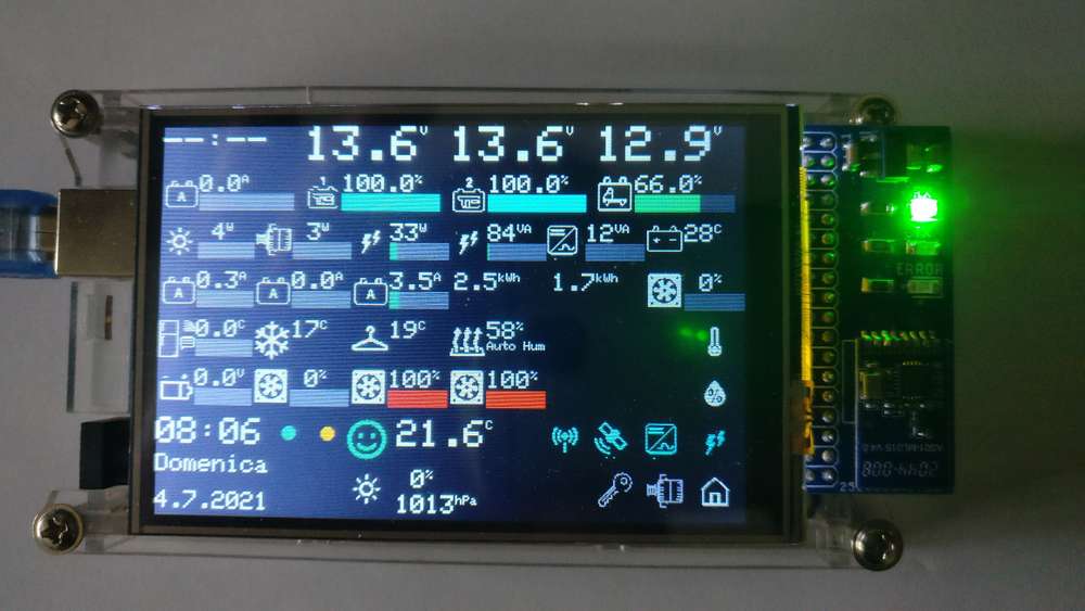
@berkseo
Hey. Our own berkseo is on Hackaday. Congrats!https://hackaday.com/2021/03/11/nrf52-weather-station-gives-forecast-with-style/
Now this project looks like this:
https://www.instagram.com/p/CkikRzAtECe/?utm_source=ig_web_button_share_sheet
![20210531_203447[1].jpg](/assets/uploads/files/1623549756369-20210531_203447-1-resized.jpg)
![20210531_203249[1].jpg](/assets/uploads/files/1623549833480-20210531_203249-1-resized.jpg)
![20210612_201851[1].jpg](/assets/uploads/files/1623550358863-20210612_201851-1-resized.jpg)
![20210612_201851[1].jpg](/assets/uploads/files/1623549644772-20210612_201851-1-resized.jpg)