What did you build today (Pictures) ?

-
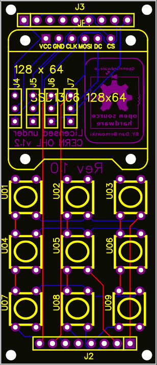
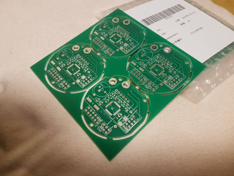
So here is an updated board layout that with the new controller board layout will allow for either a 6 pin SPI or 4 pin I2C OLED display. J4 through J7 are jumper headers that tell whether you are using a 6 pin SPI or 4 pin I2C display.
-
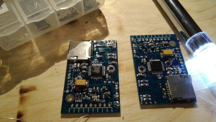
Building some loggers which i might sell later on.
-
And want to make a tip about smd component organisation...
-
@neverdie I thought about adding jumpers, but being that these are in-wall switches which are pretty much permanent, and the fact that because of space the OLED display needs to be soldered in place, there's not much chance of the display getting changed from I2C to SPI or vice versa. I figured that the pads could just be bridged one way or the other depending on configuration.
-
And want to make a tip about smd component organisation...
@sundberg84 said in What did you build today (Pictures) ?:
And want to make a tip about smd component organisation...
I think we should make another topic for this kind of tips ? We could discuss pros and cons and give reference to online shops to buy items, your boxes are quite nice for DIP components and small breakout boards, where are they from ?
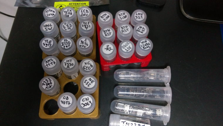
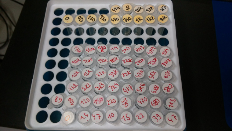
For SMDs components I went for the lab supplies on AliExpress, I started to sort my SMD chips using 5ml tubes and 3D printed holders, I need to print more holders to sort by categories as it's a bit messy at the moment. I put a bigger sticker on the side of tubes with more details as top sticker is pretty small :D Same holders can also holder bigger tubes for bigger stuff like here mini/micro USB plugs.
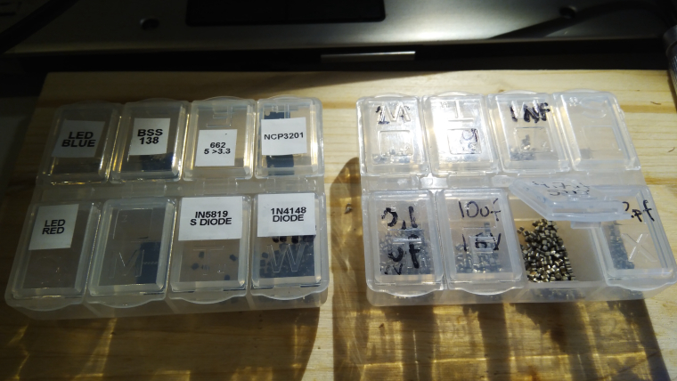
For resistors, capacitors, inductances, ... I went for lab tube boxes. I use smaller tubes (1.5 or 2ml) but they can hold probably thousands of 0603 or 0402 and even hundreds of the 0805 and 1206 resistors. I use different colors to differentiate size (and later precision/voltage/... when I'll have more boxes) and put bigger stickers on the lid of the box with information for each color.
-
Here, I like using smd books but of course I have a lot of these little boxes, too much though, and not enough!
Little boxes are nice but not very handy as you spend your time to reorganize them. Whereas I can have dedicated pages in books for my designs. Sure I could have dedicated boxes, but that takes more place and I don't have to search for a partvalue in hundreds of box. -
@sundberg84 said in What did you build today (Pictures) ?:
And want to make a tip about smd component organisation...
I think we should make another topic for this kind of tips ? We could discuss pros and cons and give reference to online shops to buy items, your boxes are quite nice for DIP components and small breakout boards, where are they from ?
For SMDs components I went for the lab supplies on AliExpress, I started to sort my SMD chips using 5ml tubes and 3D printed holders, I need to print more holders to sort by categories as it's a bit messy at the moment. I put a bigger sticker on the side of tubes with more details as top sticker is pretty small :D Same holders can also holder bigger tubes for bigger stuff like here mini/micro USB plugs.
For resistors, capacitors, inductances, ... I went for lab tube boxes. I use smaller tubes (1.5 or 2ml) but they can hold probably thousands of 0603 or 0402 and even hundreds of the 0805 and 1206 resistors. I use different colors to differentiate size (and later precision/voltage/... when I'll have more boxes) and put bigger stickers on the lid of the box with information for each color.
-
@neverdie I have plastic boxes from my local supermarket, I put components/breakout boards etc inside in their antistatic bags, then align them on their side in drawers. Less convenient to access but at least it's cleaned and ordered :)
-
Great fun to see all these build pictures!
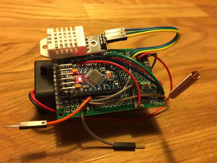
My pic of the day is a trivial battery powered DHT22 sensor just to try things out with prototyping, programming and connecting to OpenHAB. This is my first project since highschool. (The gw and first sensor is on a breadboard.)
It feels great to be soldering again after almost 30 years and I'm really looking forward to step into the MySensors world!
-
Great fun to see all these build pictures!
My pic of the day is a trivial battery powered DHT22 sensor just to try things out with prototyping, programming and connecting to OpenHAB. This is my first project since highschool. (The gw and first sensor is on a breadboard.)
It feels great to be soldering again after almost 30 years and I'm really looking forward to step into the MySensors world!
-
Today I finished the coding for my prototype of a laser distance sensor (intended to measure the water level for my automatic in-door flower watering pump). The sensor is connected via I²C and has sleep pin.
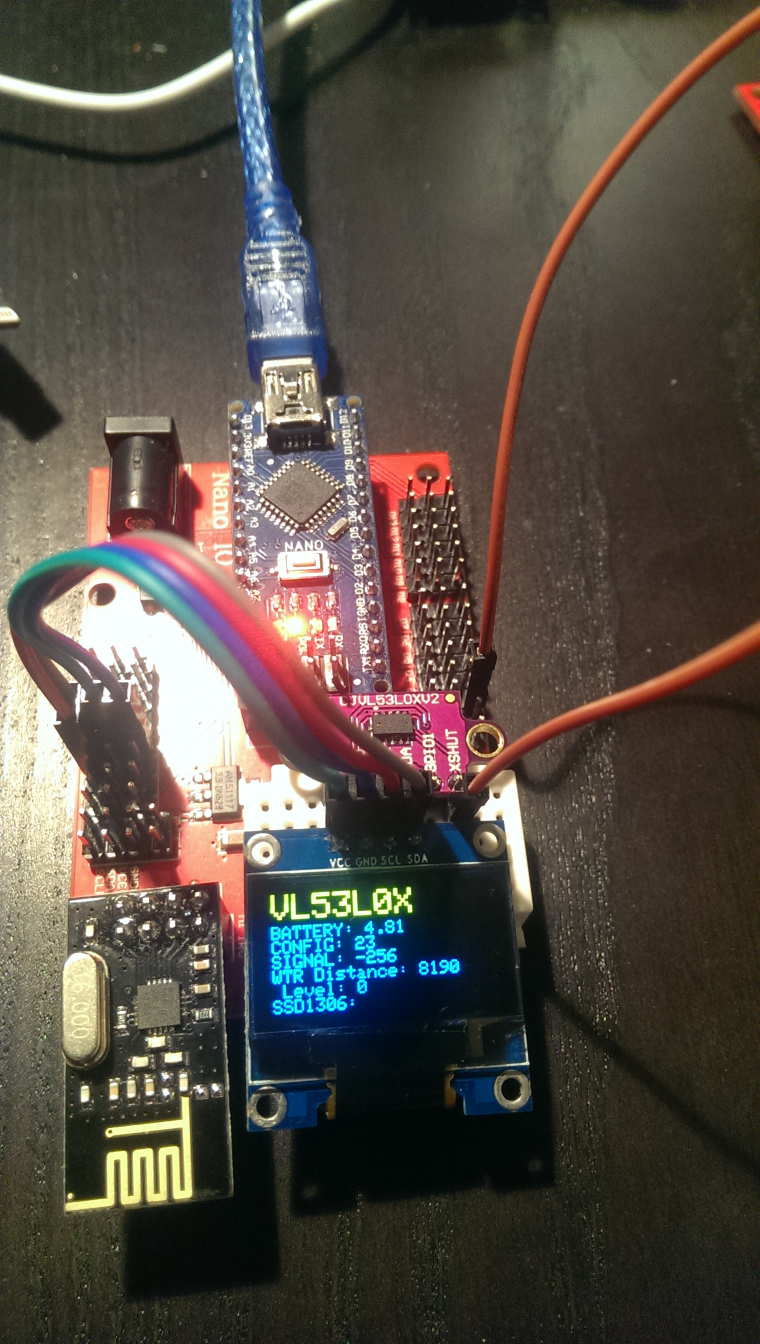
The most work was implementing support for the VL52L0X laser distance sensor and for my 128x64 OLED display to NodeManager (PRs submitted as https://github.com/mysensors/NodeManager/pull/244 and https://github.com/mysensors/NodeManager/pull/245).
The OLED is really useful when prototyping sensor nodes. Out of the box, my NodeManager OLED implemention will display the values of all attached sensors without any coding. Simply create the DisplaySSD1306 after all other sensors, and the OLED will pick up and display all sensors automatically...
Once everything works, of course the OLED is not desired for the water level sensor running on batteries...
-
Today I finished the coding for my prototype of a laser distance sensor (intended to measure the water level for my automatic in-door flower watering pump). The sensor is connected via I²C and has sleep pin.
The most work was implementing support for the VL52L0X laser distance sensor and for my 128x64 OLED display to NodeManager (PRs submitted as https://github.com/mysensors/NodeManager/pull/244 and https://github.com/mysensors/NodeManager/pull/245).
The OLED is really useful when prototyping sensor nodes. Out of the box, my NodeManager OLED implemention will display the values of all attached sensors without any coding. Simply create the DisplaySSD1306 after all other sensors, and the OLED will pick up and display all sensors automatically...
Once everything works, of course the OLED is not desired for the water level sensor running on batteries...
-
@gohan I'm using the SSD1306Ascii library, which does not use a display buffer and does not support graphics, only text. The drawback is that to prevent screen flickering, you have to manually clean each line of text to the EOL. Otherwise letters that are not overwritten by new text will not be cleared. See my PR for NodeManager how it works. With my approach, there is absolutely no screen flicker, the display updates properly and the memory requirements are minimal (the library docs say its 53 bytes)
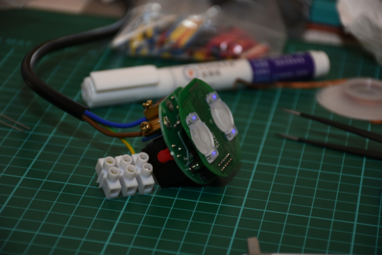
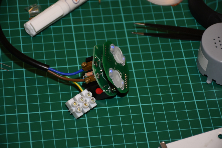
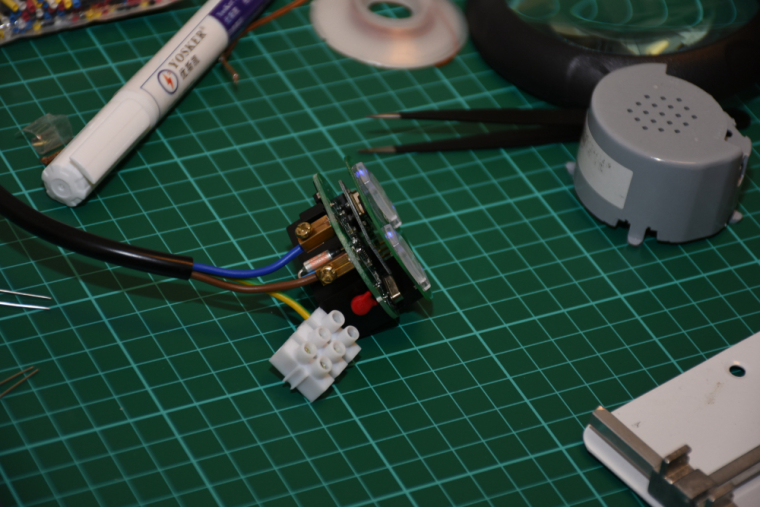
I now have revision 1.0 of my OLED keypad posted on OpenHardware.io. My first revision of the board allows for either the 6 pin SPI or 4 pin I2C versions of the SSD1306 OLED display. The 9 button configuration allows for several different combinations of buttons depending on the needs of the user.
https://www.openhardware.io/view/546 -
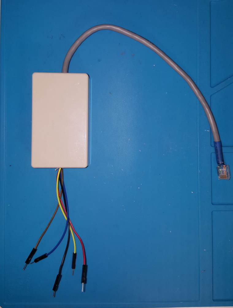
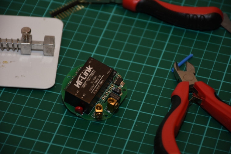
I found out that the brinks solution I build some time ago could be upgraded with a nice additional feature. 'Filter detection'.
I created a cheat sheet as my device was equiped with RJ11 connector and 3 wires. I needed to convert it to RJ12 with filter detection.
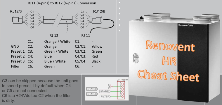
A nice black conversion box Output wires are the same colour as the original RJ 1 wire. With 2 extra wires 3,3v or 5v for the digital 'one' on the arduino.
-
@andrew said in What did you build today (Pictures) ?:
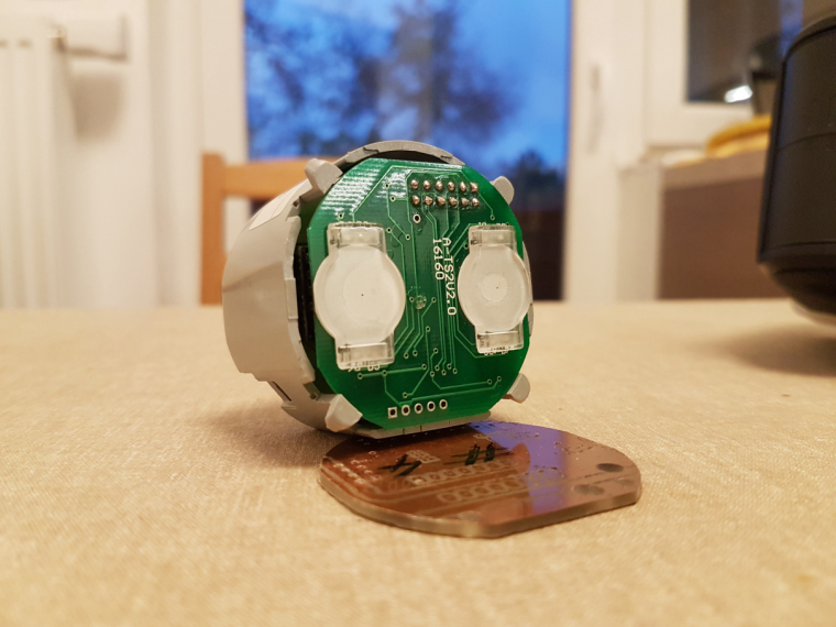
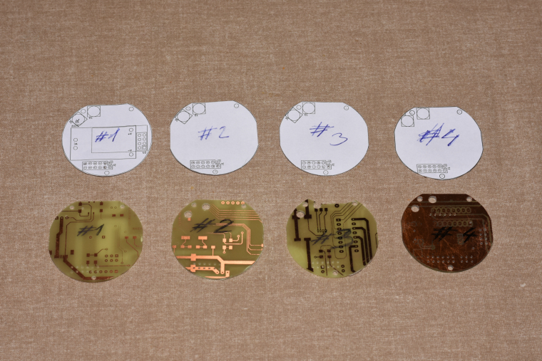
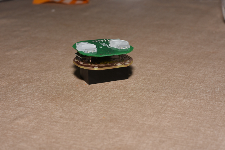
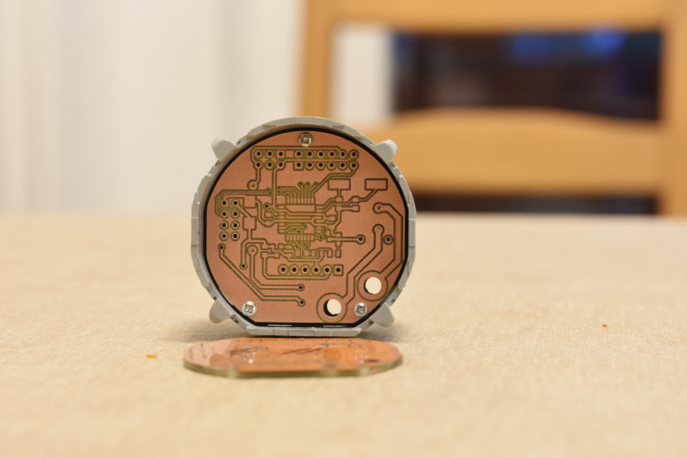
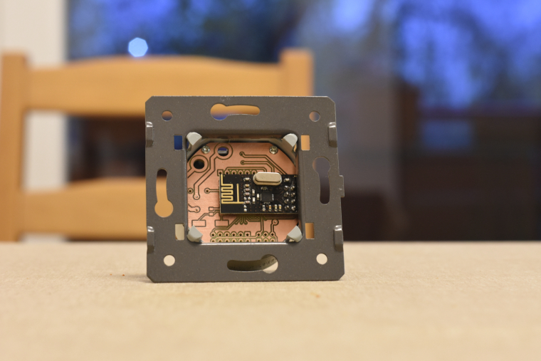
so, it is ready. I mean ready to SW development :) both the schematic and pcb design is now confirmed and fortunately theory meets the practice :)
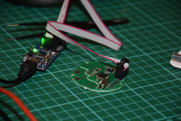
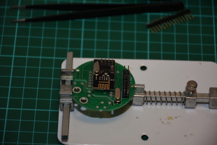
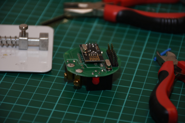
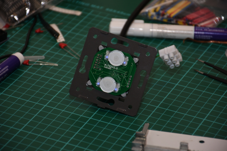
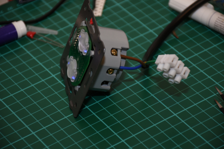
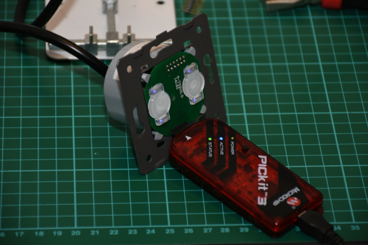
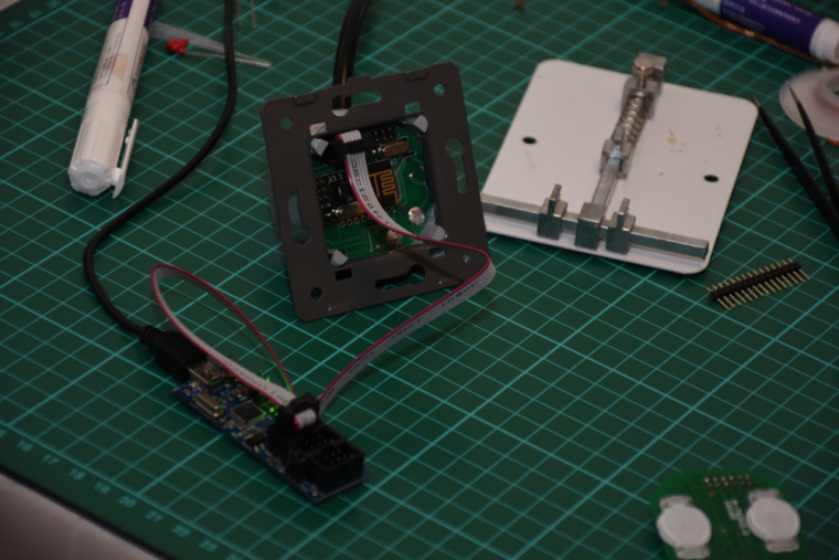
it is assembled, programmed, tested, everything works as expected.
I did not mount it to the wall so far (I'll need a controller and real actuators first), but there was no issue with the communication between two nrf modules (both with PCB antenna) from cca 6 meter distance + 2 walls (10 cm brick) in between.the touch panel's firmware will be enhanced as well as the controller's firmware, at the moment the touch sensing is reliable and a PoC code run on both of them for testing/debugging purposes. for the controller board I'm collecting additional information for the development on the following link:
https://forum.mysensors.org/topic/8831/which-sensor-and-msg-type-for-switch-dimmer-node-sender-only