Skip to content
  • MySensors
  • OpenHardware.io
  • Categories
  • Recent
  • Tags
  • Popular
Skins
  • Light
  • Brite
  • Cerulean
  • Cosmo
  • Flatly
  • Journal
  • Litera
  • Lumen
  • Lux
  • Materia
  • Minty
  • Morph
  • Pulse
  • Sandstone
  • Simplex
  • Sketchy
  • Spacelab
  • United
  • Yeti
  • Zephyr
  • Dark
  • Cyborg
  • Darkly
  • Quartz
  • Slate
  • Solar
  • Superhero
  • Vapor

  • Default (No Skin)
  • No Skin
Collapse
Brand Logo
  1. Home
  2. General Discussion
  3. What did you build today (Pictures) ?

What did you build today (Pictures) ?

Scheduled Pinned Locked Moved General Discussion
1.1k Posts 105 Posters 202.8k Views 98 Watching
  • Oldest to Newest
  • Newest to Oldest
  • Most Votes
Reply
  • Reply as topic
Log in to reply
This topic has been deleted. Only users with topic management privileges can see it.
  • sundberg84S Offline
    sundberg84S Offline
    sundberg84
    Hardware Contributor
    wrote on last edited by sundberg84
    #553

    Yesterday I tested the new EasyPCB with RFM radio and hardware signing. Worked out as expected and I'm going to release all files soon.

    I haven't tested the flash part yet but I'm hoping this is working as well.

    This picture will be a part of a new video with me building my new RFM69 serial gateway using signing.

    Anyone they can guess which issue I had when I took the photo?
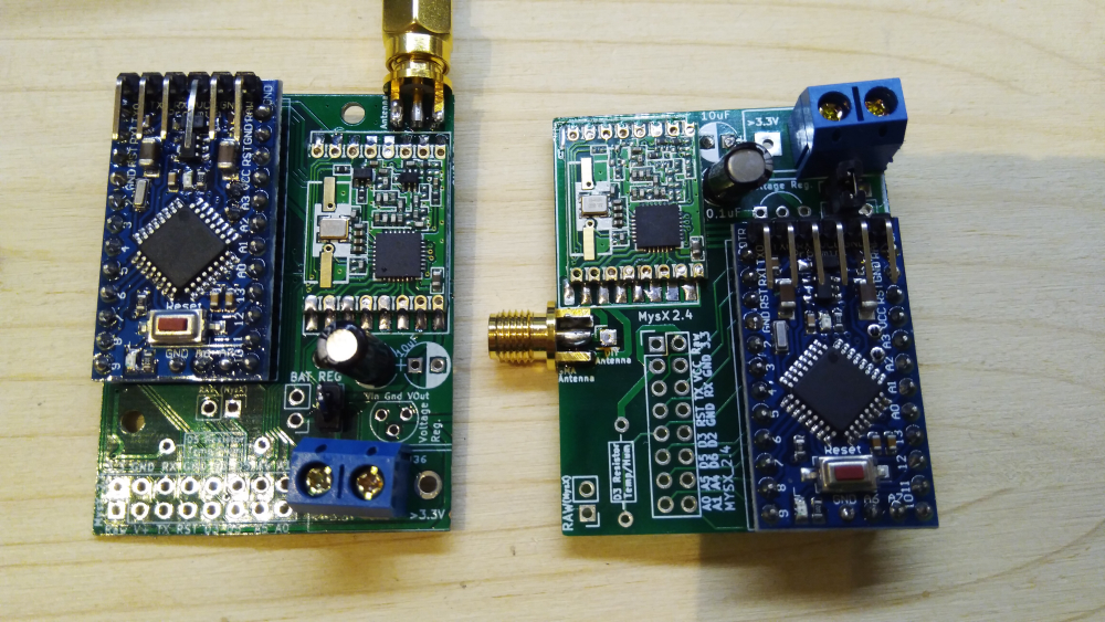
    0_1527916350367_IMG_20180601_140009.jpg
    Rev9 vs Rev10 (inkl signing) rfm gw

    Controller: Proxmox VM - Home Assistant
    MySensors GW: Arduino Uno - W5100 Ethernet, Gw Shield Nrf24l01+ 2,4Ghz
    MySensors GW: Arduino Uno - Gw Shield RFM69, 433mhz
    RFLink GW - Arduino Mega + RFLink Shield, 433mhz

    M 1 Reply Last reply
    0
    • sundberg84S sundberg84

      Yesterday I tested the new EasyPCB with RFM radio and hardware signing. Worked out as expected and I'm going to release all files soon.

      I haven't tested the flash part yet but I'm hoping this is working as well.

      This picture will be a part of a new video with me building my new RFM69 serial gateway using signing.

      Anyone they can guess which issue I had when I took the photo?

      0_1527916350367_IMG_20180601_140009.jpg
      Rev9 vs Rev10 (inkl signing) rfm gw

      M Offline
      M Offline
      mickecarlsson
      wrote on last edited by mickecarlsson
      #554

      @sundberg84 the RFM69 is soldered 180 degrees wrong on the new board :white_frowning_face:

      sundberg84S 1 Reply Last reply
      0
      • M mickecarlsson

        @sundberg84 the RFM69 is soldered 180 degrees wrong on the new board :white_frowning_face:

        sundberg84S Offline
        sundberg84S Offline
        sundberg84
        Hardware Contributor
        wrote on last edited by sundberg84
        #555

        @mickecarlsson interesting thought but no because the radio on rev9 isn't soldered in the image (but wrong rotated as you noticed). The hardware on that image is working. I added a HW radio without noticing so with the old code I just got no reply/Nack. I had to add the HW define.

        Controller: Proxmox VM - Home Assistant
        MySensors GW: Arduino Uno - W5100 Ethernet, Gw Shield Nrf24l01+ 2,4Ghz
        MySensors GW: Arduino Uno - Gw Shield RFM69, 433mhz
        RFLink GW - Arduino Mega + RFLink Shield, 433mhz

        1 Reply Last reply
        0
        • vladimirV Offline
          vladimirV Offline
          vladimir
          wrote on last edited by
          #556

          Today I finally finished my second RGB LED lighting in the room. Next is the LED illumination of the perimeter of the bed. Under the bed, I want to place a motion sensor so that it reacts when I get out of bed at night.
          alt text

          GertSandersG 1 Reply Last reply
          5
          • sundberg84S Offline
            sundberg84S Offline
            sundberg84
            Hardware Contributor
            wrote on last edited by sundberg84
            #557

            Redesigning my nodes in the RFM69 network to be signed using EasyPCB 10. Today it was my beer cooler node (because it's very important the beer temperature is secured). In the same time I'm implementing @gohan idea with two temp points (top and bottom).
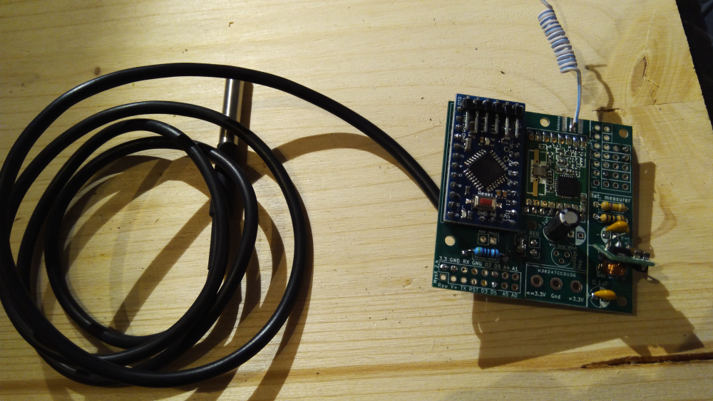
            0_1528134204572_IMG_20180604_194024.jpg

            Controller: Proxmox VM - Home Assistant
            MySensors GW: Arduino Uno - W5100 Ethernet, Gw Shield Nrf24l01+ 2,4Ghz
            MySensors GW: Arduino Uno - Gw Shield RFM69, 433mhz
            RFLink GW - Arduino Mega + RFLink Shield, 433mhz

            1 Reply Last reply
            3
            • vladimirV vladimir

              Today I finally finished my second RGB LED lighting in the room. Next is the LED illumination of the perimeter of the bed. Under the bed, I want to place a motion sensor so that it reacts when I get out of bed at night.
              alt text

              GertSandersG Offline
              GertSandersG Offline
              GertSanders
              Hardware Contributor
              wrote on last edited by
              #558

              @vladimir

              you could use this under the bed:

              https://www.aliexpress.com/item/Free-Shipping-5-Pieces-RCWL-0516-Microwave-Radar-Sensor-Module-Human-Body-Induction-Switch-Module/32773310756.html?spm=a2g0s.9042311.0.0.27424c4dQaNm0K

              It works like an infrared sensor (same three pins), but it does not need a line of sight. It just reacts to movement as this results in a disturbance in the emitted radio signal. Works very well on my clock :-)

              The "high" value when movement is detected is not a full 5V, so I test the Out pin as an analog pin. Anything above 2.5V is an activation due to movement.

              vladimirV 1 Reply Last reply
              3
              • GertSandersG GertSanders

                @vladimir

                you could use this under the bed:

                https://www.aliexpress.com/item/Free-Shipping-5-Pieces-RCWL-0516-Microwave-Radar-Sensor-Module-Human-Body-Induction-Switch-Module/32773310756.html?spm=a2g0s.9042311.0.0.27424c4dQaNm0K

                It works like an infrared sensor (same three pins), but it does not need a line of sight. It just reacts to movement as this results in a disturbance in the emitted radio signal. Works very well on my clock :-)

                The "high" value when movement is detected is not a full 5V, so I test the Out pin as an analog pin. Anything above 2.5V is an activation due to movement.

                vladimirV Offline
                vladimirV Offline
                vladimir
                wrote on last edited by
                #559

                @gertsanders many thanks!:raised_hands: This is very interesting, I did not previously hear about such a sensor.
                I understand correctly that it can be placed in a wooden case and it can work through it? Since the tree does not reflect its waves.
                If this is so, will not it respond to the movement of the bed frame or my movements when I'm on the bed?...:thinking_face:

                1 Reply Last reply
                0
                • gohanG Offline
                  gohanG Offline
                  gohan
                  Mod
                  wrote on last edited by
                  #560

                  I tried some of those radar sensors and are very sensitive, they could detect even if you move in the bed. In addition I'd rather not sleep next to a 5 Ghz radar emitter 😅

                  vladimirV 1 Reply Last reply
                  1
                  • gohanG gohan

                    I tried some of those radar sensors and are very sensitive, they could detect even if you move in the bed. In addition I'd rather not sleep next to a 5 Ghz radar emitter 😅

                    vladimirV Offline
                    vladimirV Offline
                    vladimir
                    wrote on last edited by
                    #561

                    @gohan Is there a chance to wake up a little toasted?:sweat_smile:

                    1 Reply Last reply
                    0
                    • gohanG Offline
                      gohanG Offline
                      gohan
                      Mod
                      wrote on last edited by
                      #562

                      fortunately the power is low, but still in the wifi power range and it is transmitting 24/7

                      NeverDieN 1 Reply Last reply
                      0
                      • gohanG gohan

                        fortunately the power is low, but still in the wifi power range and it is transmitting 24/7

                        NeverDieN Offline
                        NeverDieN Offline
                        NeverDie
                        Hero Member
                        wrote on last edited by NeverDie
                        #563

                        @gohan Oh, pish posh. It's made in China and sold for peanuts! What could possibly go wrong?

                        1 Reply Last reply
                        1
                        • gohanG Offline
                          gohanG Offline
                          gohan
                          Mod
                          wrote on last edited by
                          #564

                          I think it would be faster to answer to "what could possibly not go wrong"

                          NeverDieN 1 Reply Last reply
                          1
                          • gohanG gohan

                            I think it would be faster to answer to "what could possibly not go wrong"

                            NeverDieN Offline
                            NeverDieN Offline
                            NeverDie
                            Hero Member
                            wrote on last edited by NeverDie
                            #565

                            @gohan What could possibly not go wrong? :volcano:

                            1 Reply Last reply
                            0
                            • wallyllamaW Offline
                              wallyllamaW Offline
                              wallyllama
                              wrote on last edited by
                              #566

                              So these radar motion sensors are actually quite impressive, the ones with just analog output only have 1 transistor, the rest of the circuit is formed by the pcb traces. Weird, but it works. They can be hacked (sawtooth wave for power) to give a distance reading instead of doppler. The signal processing is too much for an arduino, but it is doable.

                              The other ones actually use the same chip as the most common pir devices.

                              1 Reply Last reply
                              0
                              • sundberg84S Offline
                                sundberg84S Offline
                                sundberg84
                                Hardware Contributor
                                wrote on last edited by
                                #567

                                0_1529180496679_IMG_20180616_221328.jpg

                                Suddenly my outdoor lightsensor stopped working. A good time to have a portal debugger. Everything seems fine in the log though... All ST:ok but for some reason it doesn't show up in domotocz.... Well that have to be tomorrows project.

                                Controller: Proxmox VM - Home Assistant
                                MySensors GW: Arduino Uno - W5100 Ethernet, Gw Shield Nrf24l01+ 2,4Ghz
                                MySensors GW: Arduino Uno - Gw Shield RFM69, 433mhz
                                RFLink GW - Arduino Mega + RFLink Shield, 433mhz

                                1 Reply Last reply
                                1
                                • sundberg84S Offline
                                  sundberg84S Offline
                                  sundberg84
                                  Hardware Contributor
                                  wrote on last edited by
                                  #568

                                  Another node went down today... a repeater this time. Well... quickly a new one with additinal updates compared to old. (PA/Lna and Mysensors 2.3)
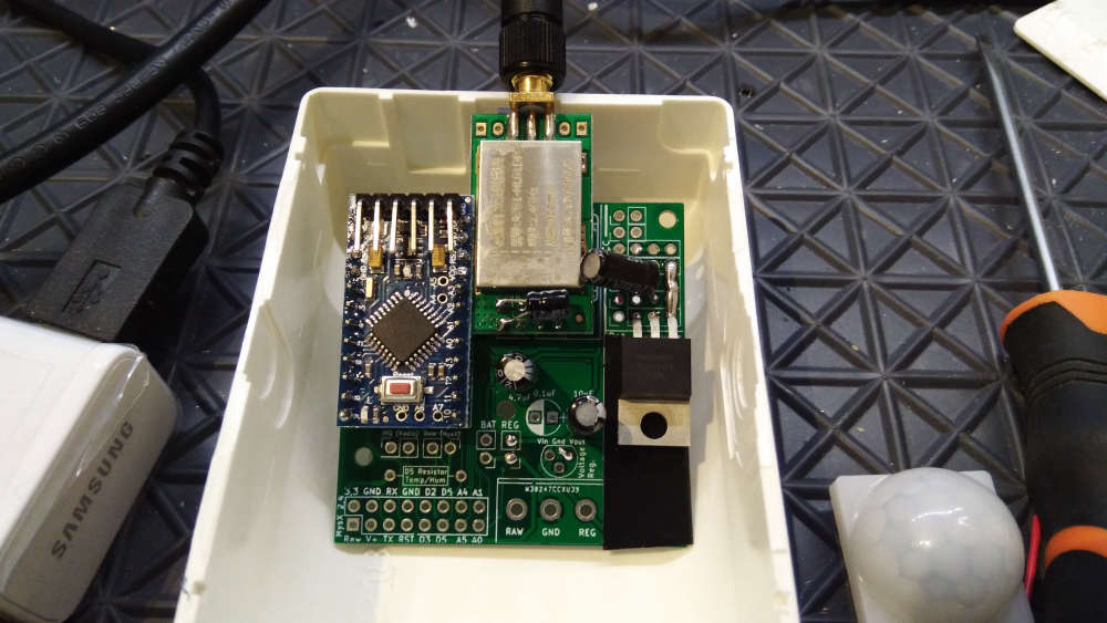
                                  0_1529854177302_IMG_20180624_153507.jpg

                                  Controller: Proxmox VM - Home Assistant
                                  MySensors GW: Arduino Uno - W5100 Ethernet, Gw Shield Nrf24l01+ 2,4Ghz
                                  MySensors GW: Arduino Uno - Gw Shield RFM69, 433mhz
                                  RFLink GW - Arduino Mega + RFLink Shield, 433mhz

                                  1 Reply Last reply
                                  2
                                  • Nca78N Offline
                                    Nca78N Offline
                                    Nca78
                                    Hardware Contributor
                                    wrote on last edited by
                                    #569

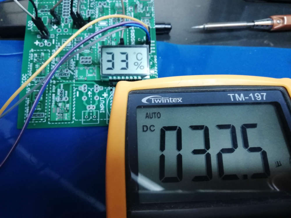
                                    I made a working version of my test board with PCF85176 LCD driver, finally reaching some decently low current consumption for an always on display. There are still some possible gains to make with lower driver voltage, and with a more recent driver that should allow to go as low as 5uA.
                                    alt text

                                    1 Reply Last reply
                                    3
                                    • dbemowskD Offline
                                      dbemowskD Offline
                                      dbemowsk
                                      wrote on last edited by
                                      #570

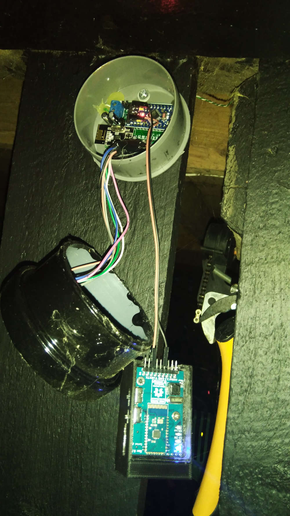
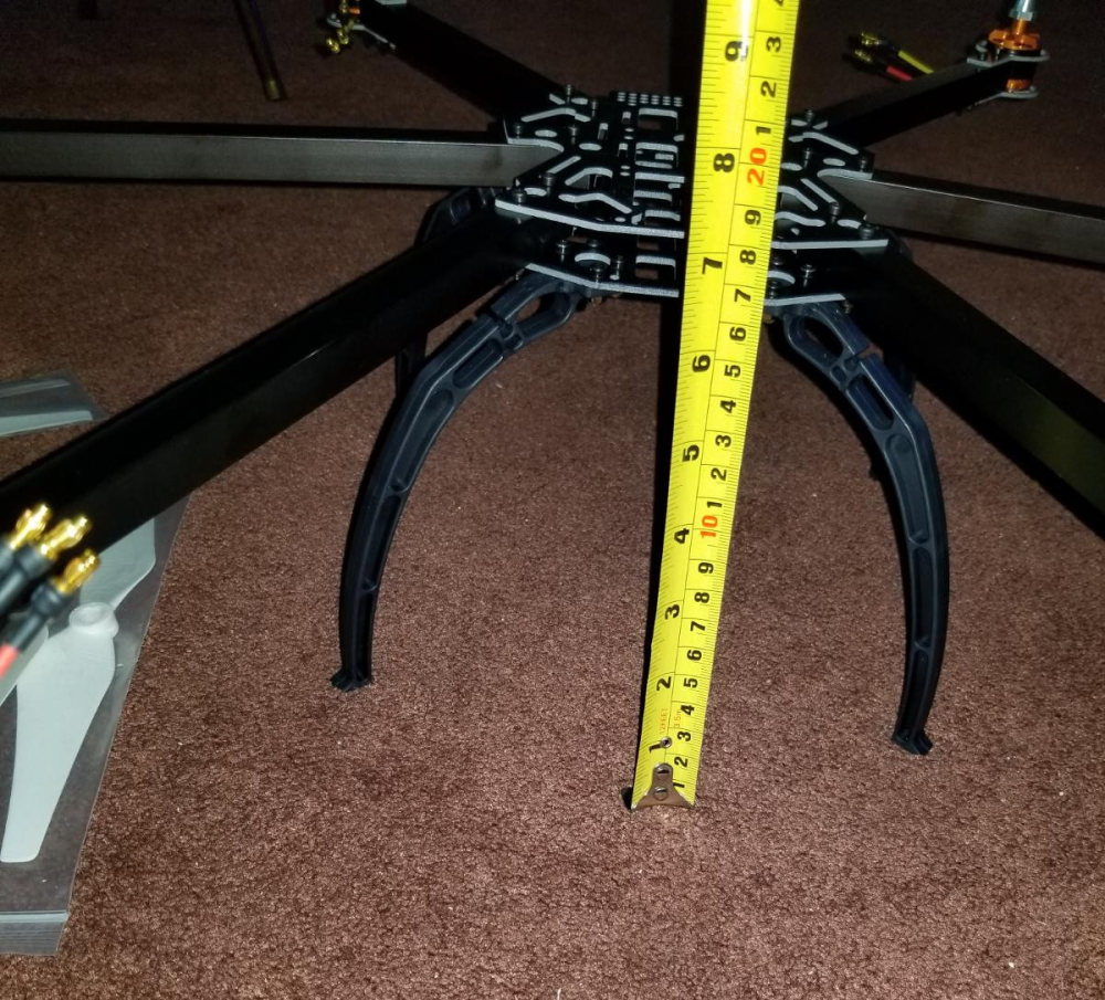
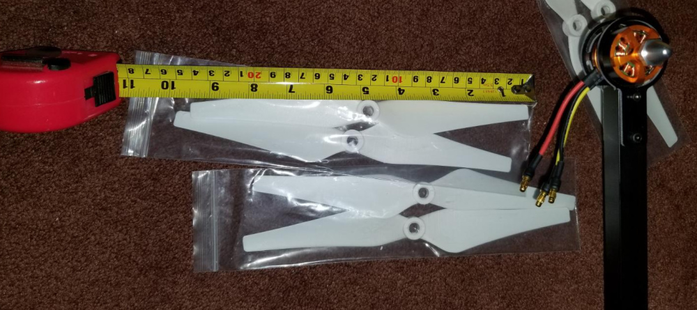
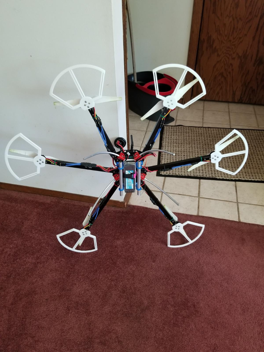
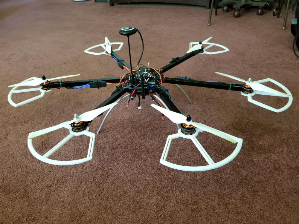
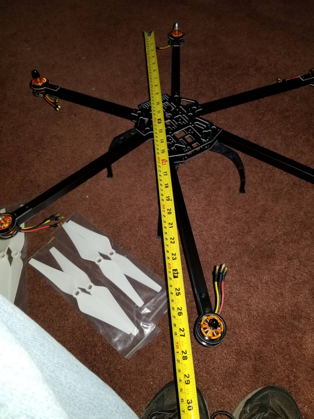
                                      Though not MySensors related, I thought I'd post my latest build that has been consuming a lot of my time lately. This is the main reason I haven't been on the forum much lately. I bought a drone kit recently. Here are some pics from the initial assembly:
                                      0_1529865599257_6cb603d6-6e77-4f65-98b2-32cbd703de6e-image.png
                                      0_1529865626778_5bb010ca-c35a-439f-9692-920fbdfcda7d-image.png
                                      0_1529865650762_bb4e8b1d-dffb-49a9-8769-74567b7cd332-image.png

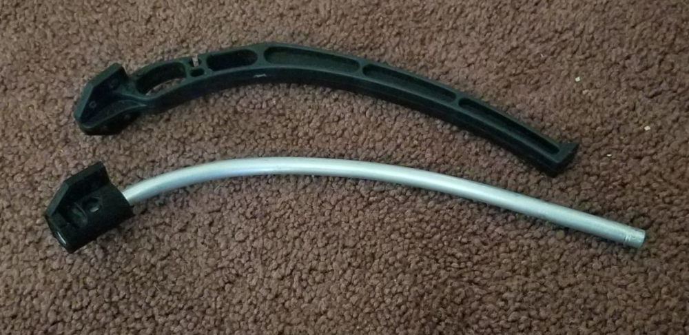
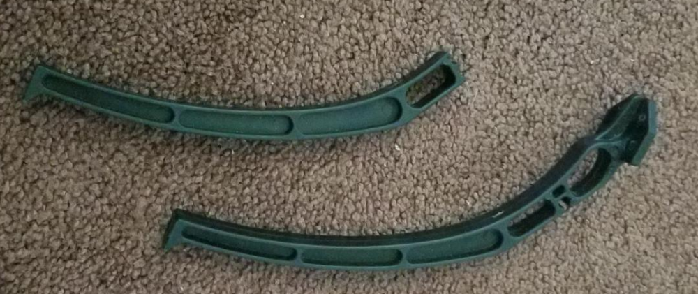
                                      Since the initial build I have flown it and from a hard landing broken one of the cheap plastic legs that it came with. I designed a replacement with my 3D printer and some 1/4 inch aluminum rod.
                                      0_1529865823787_21b6acc1-aa67-49ed-9c48-ab10d691b0c5-image.png
                                      0_1529865845366_4cde4d44-e6d0-4dc7-894a-77c38d0f958e-image.png

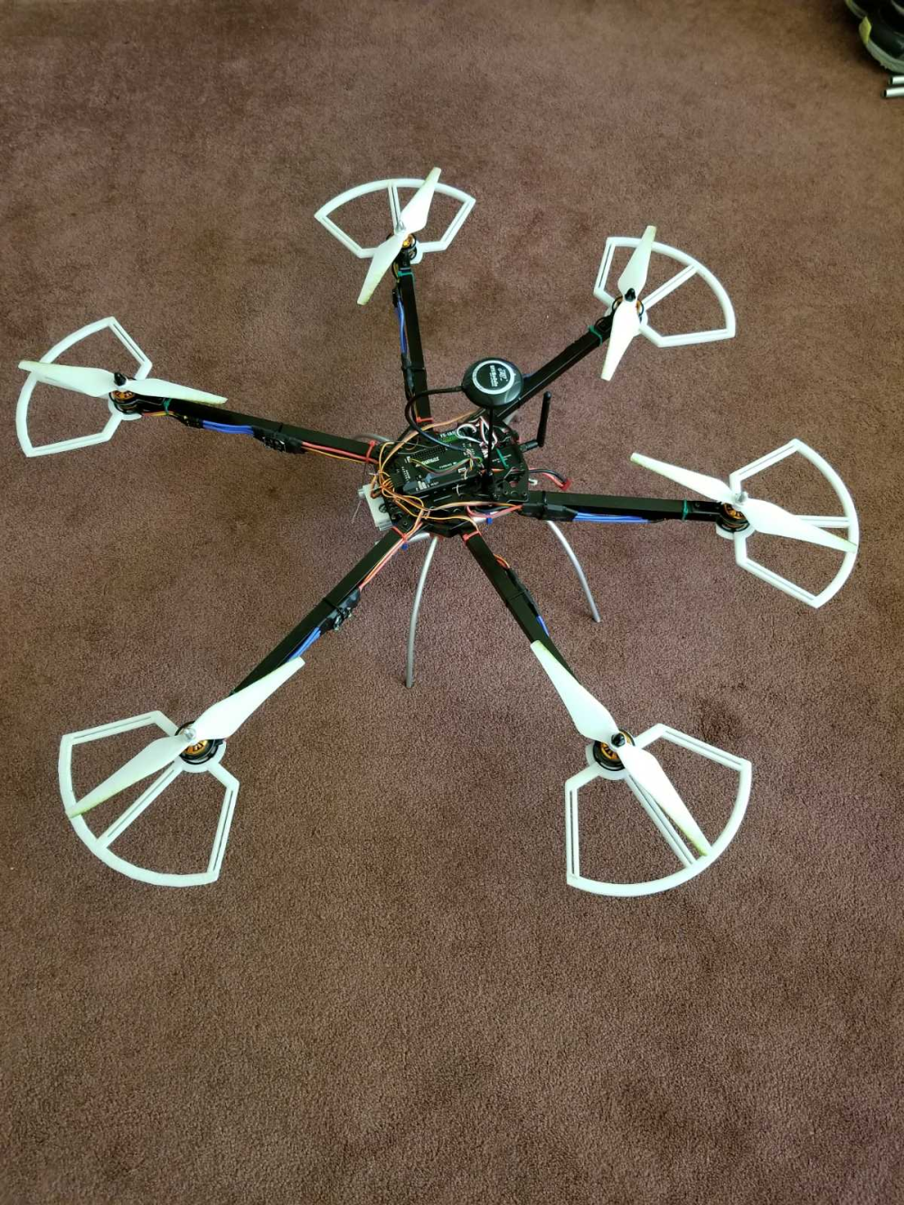
                                      Here are some pics at it's current stage. I have designed and printed some prop guards and a few other add-ons:
                                      0_1529866240417_f94e6de8-d3cc-4b8e-8c41-80f8b9dce60d-image.png
                                      0_1529866316628_d7cdb2a3-b4ee-4632-8c84-9f97f656daa3-image.png
                                      0_1529866388984_33f28a28-a295-4375-ab92-048a259f8efa-image.png

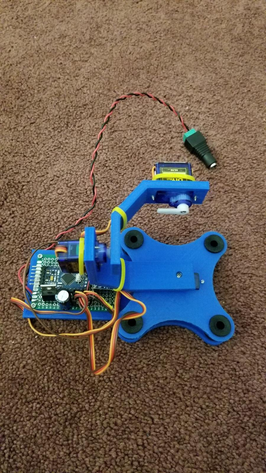
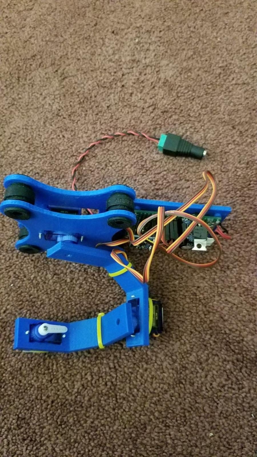
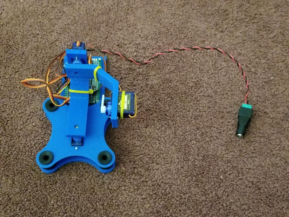
                                      I have also designed and built a small servo based 3 axis camera gimbal. The controller was built using one of my spare 5 volt pro minis and an MPU-6050 accelerometer. Still working on the parts that will attach it to the drone, and I still need to pick up an FPV camera to attach to it, but a simple FPV cam is cheap.
                                      0_1529866448927_8a3084ed-1e2f-49ac-a1f8-797ac13bec1c-image.png
                                      0_1529866856366_8e332d29-99f0-4dd4-bf3f-7ade3bc3dbd8-image.png
                                      0_1529866891384_bcf7406a-5e68-4ad6-95aa-cf3324f2cb9a-image.png

                                      Vera Plus running UI7 with MySensors, Sonoffs and 1-Wire devices
                                      Visit my website for more Bits, Bytes and Ramblings from me: http://dan.bemowski.info/

                                      1 Reply Last reply
                                      6
                                      • sundberg84S sundberg84

                                        @bjacobse it's the cheapest one on eBay with the software cheese on Linux. I think it's a replica on Andostar x500 so search Usb microscope Andostar and you will find.

                                        bjacobseB Offline
                                        bjacobseB Offline
                                        bjacobse
                                        wrote on last edited by bjacobse
                                        #571

                                        @sundberg84
                                        Thank you Sundberg for your help, I now have received my own microscope, a reply to your comments from 1 or 2 months ago

                                        1 Reply Last reply
                                        1
                                        • andrewA andrew

                                          @andrew said in What did you build today (Pictures) ?:
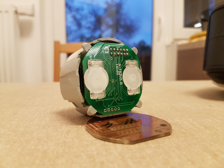
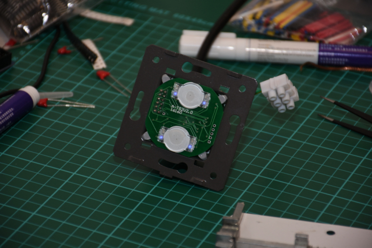
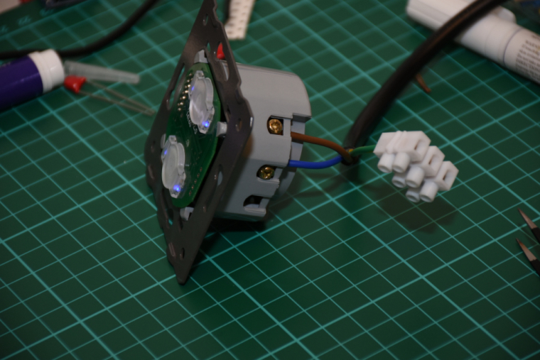
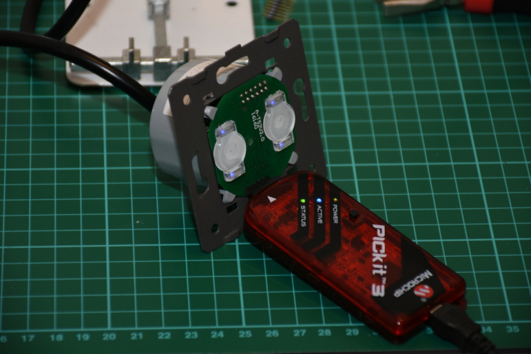
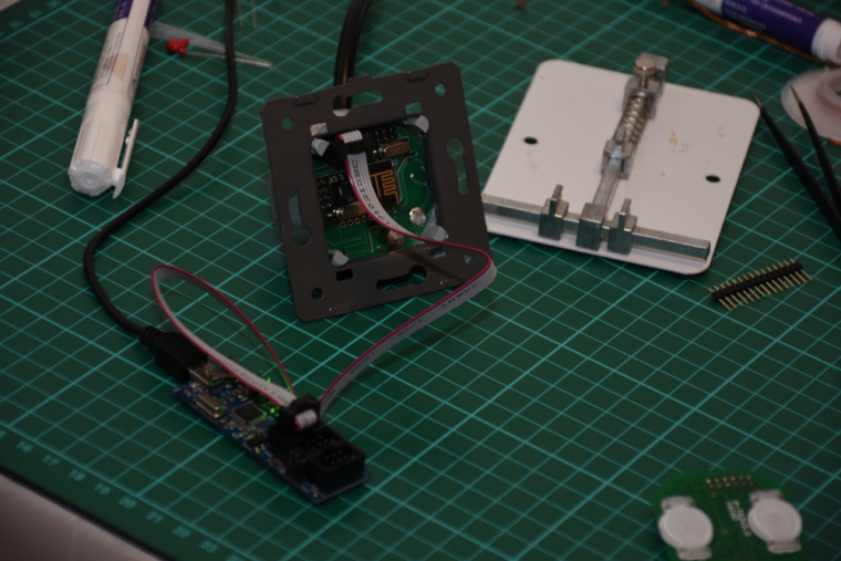
                                          0_1512830079874_small_20171119_155404.jpg 0_1512830092134_small_20171119_163354.jpg 0_1512830107562_small_20171119_163849.jpg 0_1512830119867_small_20171119_164745.jpg 0_1512830130032_small_20171119_165717.jpg 0_1512830150237_small_20171203_092353.jpg 0_1512830159490_small_20171203_163658.jpg 0_1512830169403_small_20171207_194213.jpg

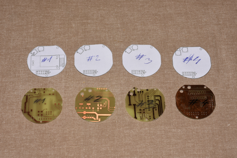
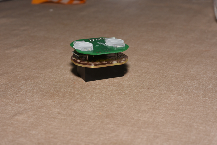
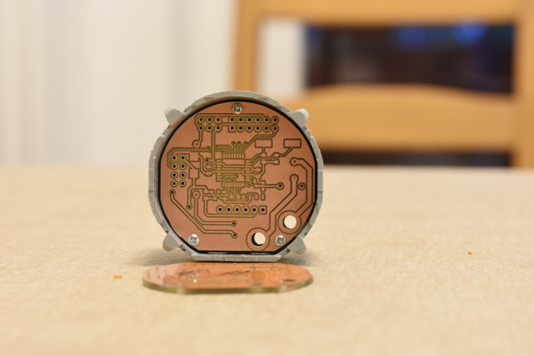
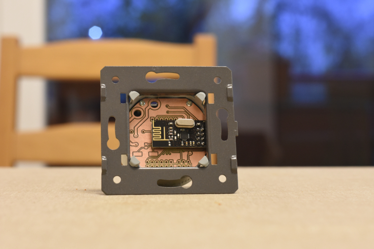
                                          so, it is ready. I mean ready to SW development :) both the schematic and pcb design is now confirmed and fortunately theory meets the practice :)
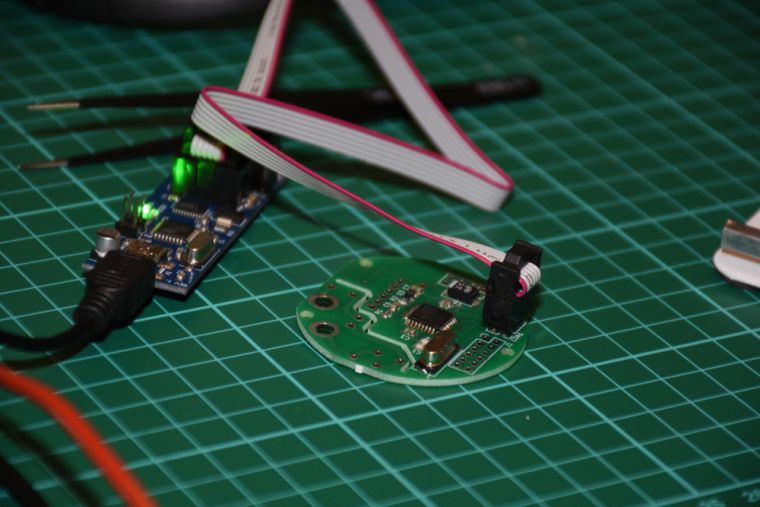
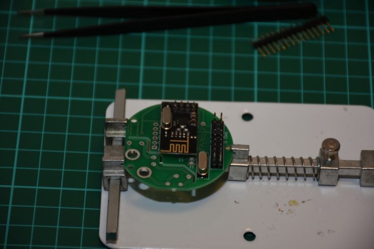
                                          0_1515090568483_small_small_20180103_235320.jpg

                                          0_1515090578447_small_small_20180104_001658.jpg

                                          0_1515090588886_small_small_20180104_003546.jpg

                                          0_1515090603769_small_small_20180104_003556.jpg

                                          0_1515090626947_small_small_20180104_004540.jpg

                                          0_1515090649476_small_small_20180104_004605.jpg

                                          0_1515090667193_small_small_20180104_004655.jpg

                                          0_1515090681698_small_small_20180104_005413.jpg

                                          0_1515090695413_small_small_20180104_005424.jpg

                                          0_1515090706426_small_small_20180104_010443.jpg

                                          0_1515090717200_small_small_20180104_010955.jpg

                                          it is assembled, programmed, tested, everything works as expected.
                                          I did not mount it to the wall so far (I'll need a controller and real actuators first), but there was no issue with the communication between two nrf modules (both with PCB antenna) from cca 6 meter distance + 2 walls (10 cm brick) in between.

                                          the touch panel's firmware will be enhanced as well as the controller's firmware, at the moment the touch sensing is reliable and a PoC code run on both of them for testing/debugging purposes. for the controller board I'm collecting additional information for the development on the following link:
                                          https://forum.mysensors.org/topic/8831/which-sensor-and-msg-type-for-switch-dimmer-node-sender-only

                                          jeremushkaJ Offline
                                          jeremushkaJ Offline
                                          jeremushka
                                          wrote on last edited by
                                          #572

                                          @andrew have you also designed the power board or do you reuse the livolo's one?

                                          andrewA 1 Reply Last reply
                                          0
                                          Reply
                                          • Reply as topic
                                          Log in to reply
                                          • Oldest to Newest
                                          • Newest to Oldest
                                          • Most Votes


                                          7

                                          Online

                                          11.7k

                                          Users

                                          11.2k

                                          Topics

                                          113.1k

                                          Posts


                                          Copyright 2025 TBD   |   Forum Guidelines   |   Privacy Policy   |   Terms of Service
                                          • Login

                                          • Don't have an account? Register

                                          • Login or register to search.
                                          • First post
                                            Last post
                                          0
                                          • MySensors
                                          • OpenHardware.io
                                          • Categories
                                          • Recent
                                          • Tags
                                          • Popular