What did you build today (Pictures) ?

-
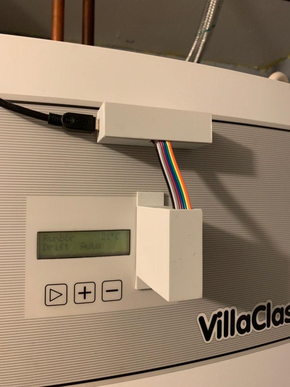
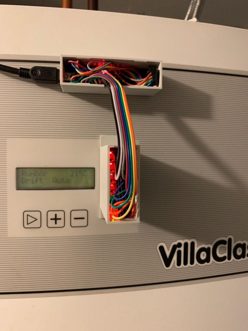
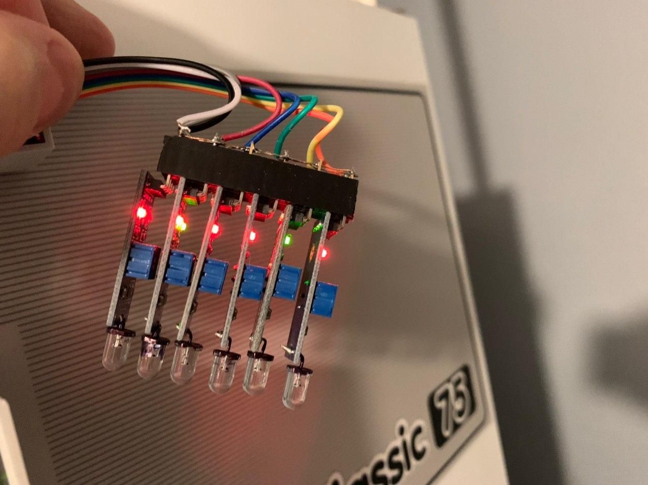
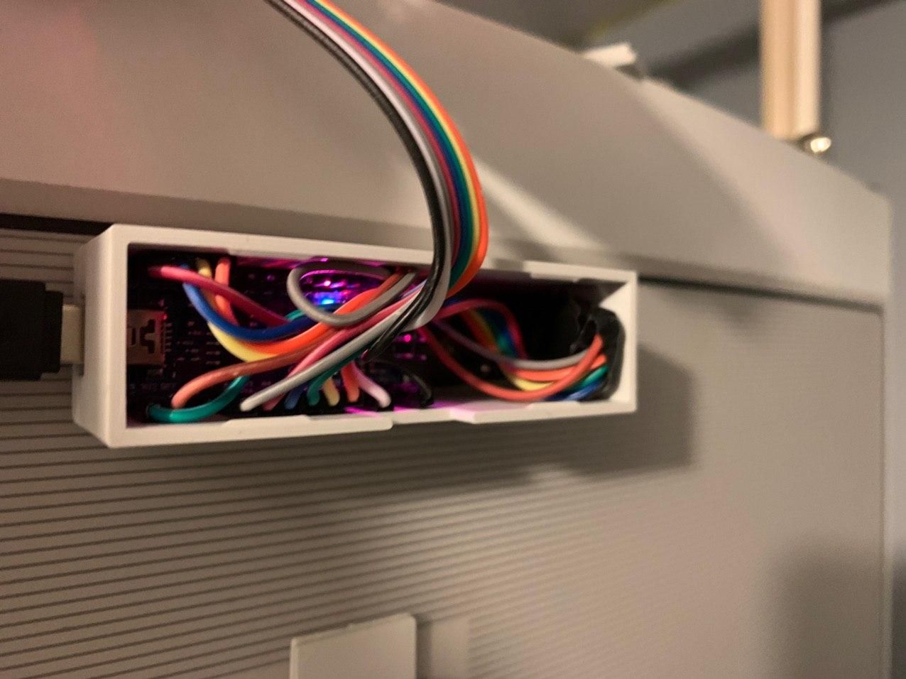
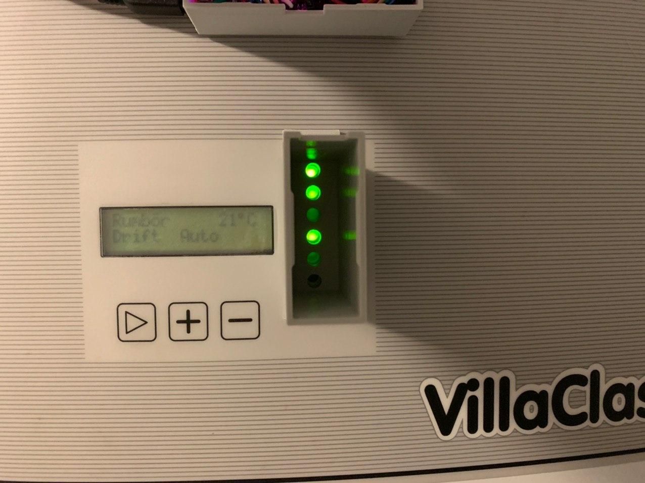
Built a heat pump monitor based on mysensors on an Nano board and a few LM393 light sensors.
It's simply reading the status LEDs and tells me if they're on or off, and it means I can correlate e.g the compressor or circulation pumps with the electricity usage read from the power meter.
Also, which actually was the main driver behind the project, it allows me to send an alarm to my phone in case the alarm LED goes on. This is usually caused by incorrect pressure somewhere in the system and can be fixed by simply restarting the system. When the alarm triggers, it shuts down everything which is a bit annoying since it can take a few hours before I notice it (usually not until I go in the shower and there is no hot water). I now have to figure out how to deal with the fact that the alarm LED is blinking, which causes a stream of "alarm ON, alarm OFF, alarm ON, ... ." etc messages in Telegram :) There should be a way to fix this in Home Assistant I hope.
An interesting thing was that I was not able to tune the sensors to give me an accurate on/off digital signal. I therefore have to read the analog signal, and in the sketch decide whether it's on or off depending on the value. The values are in the 0..1023 range and the threshold was somewhere around 1000, so I think it was too close to the end of the range for the adjustment potentiometer.
@maghac said in What did you build today (Pictures) ?:
I now have to figure out how to deal with the fact that the alarm LED is blinking, which causes a stream of "alarm ON, alarm OFF, alarm ON, ... ." etc messages in Telegram There should be a way to fix this in Home Assistant I hope.
You should fix it by using a flag for alarm led on and the last time the alarm led went on :
- when led gets on, set the "alarm on" flag in your code, save the millis() of last alarm led on in a "last alarm led on" variable
- in the loop, check status of the alarm led: if off and "alarm on" flag is on, compare millis() with "last alarm led on" time. If the difference is higher than the duration of a blink interval then your alarm is really off.
-
It's s WS2812B LED strip driver using STM32 blue pill and RFM69HCW.
I have made a few revisions previously, but this one fits an off-the-shelf enclosure and uses the pcb and enclosure lid for strain relief on the LED strip connector wires.
I like the concept of using the enclosure slots to hold the pcb. Maybe a slightly smaller enclosure next time.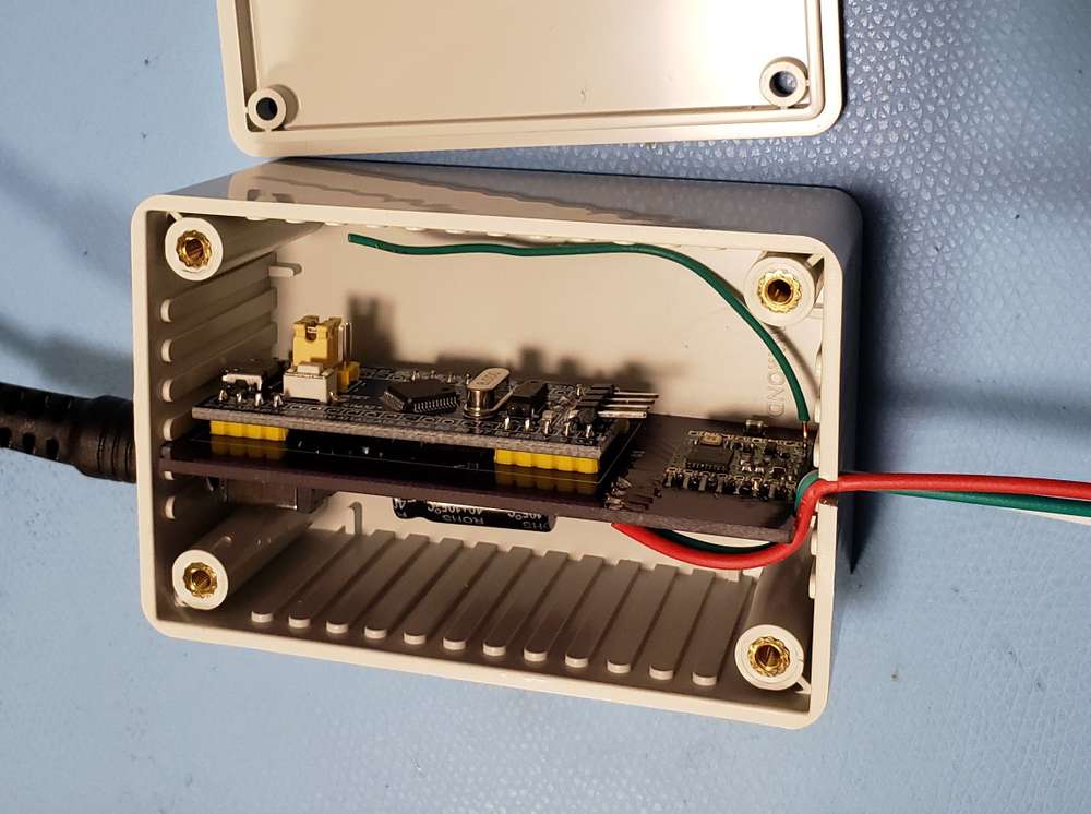
-
Today, a 5uA always on display with a PCF8553 LCD driver and a GDC1038 LCD from GoodDisplay. Power consumption varies with voltage but mostly with what segments are on/off, but at 3.3V with segments on to display data on all parts of display (2*4 digit numbers and 3 letters) it's always below 6uA.
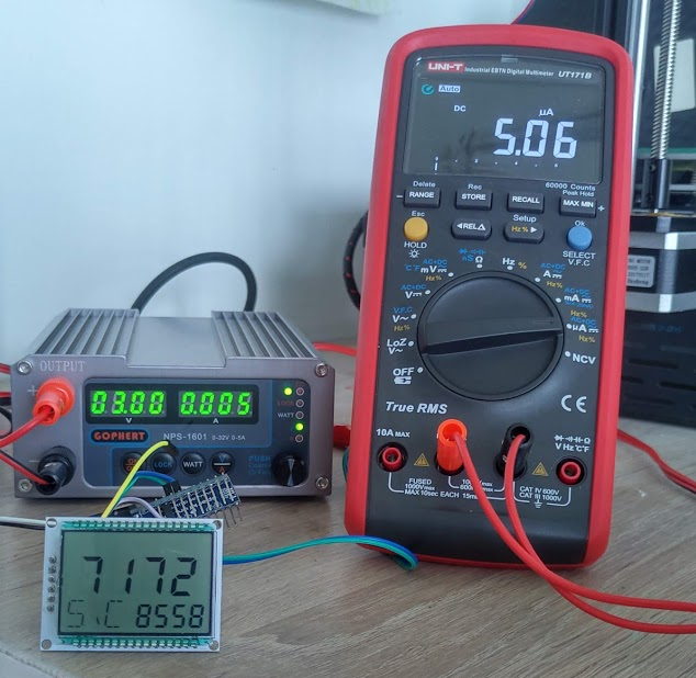
Not sure why the Youtube video won't integrate as it should, but here it is for a more animated version:
https://youtu.be/QyaC7J84vN8 -
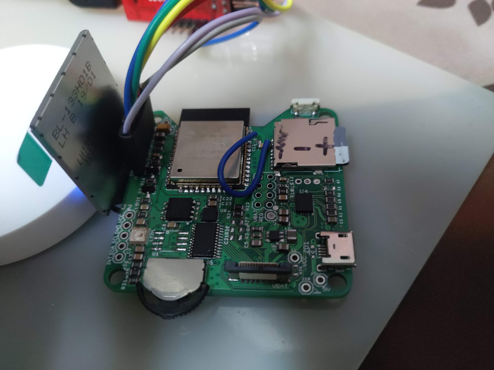
Today I finished to fix failed soldering (too old solder paste made a mess :cry: ) on the "motherboard" of my air quality sensor.
It's based on ESP32, uses a charging IC with power path so it can run on batteries for around a day or stay plugged without destroying the battery, step down from USB/battery to get VCC, storage on I2C EEPROM, flash and/or µSD card (depending on use case), one SK6812 mini RGB led as indicator, a small 240*240 IPS LCD (backlight driven directly by ESP32 pin in high drive capability mode), a 3 way switch for basic user interface + footprint for PAJ7620 gesture recognition module, accelerometer and I2C IO expander to manage the 3 way switch and interrupts from sensor modules.
Sensor modules will be added on top, connected using an FPC connector. At the moment I made only one sensor PCB able to manage usual PM, CO2 and formaldehyde sensors. Only one sensor per sensor board where an attiny841 manages the UART sensor and convert it to I2C, it also manages the 5V step up to power the sensor.
On the main board I also added an NRF24 footprint so with the same PCB I will be able to make a gateway with integrated battery backup.I'm pretty happy with the relatively well aligned components (no, I don't have OCD :D ) , too bad I had to unsolder, clean and re-solder each component as it now looks botched up. But at least everything (except a missing connection on µSD card, hence the blue wire) is working,
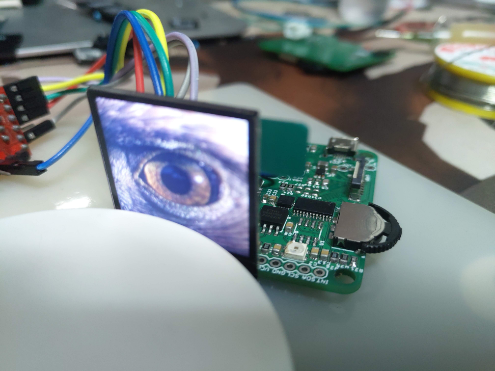
LCD test showing jpgs from SD card
-
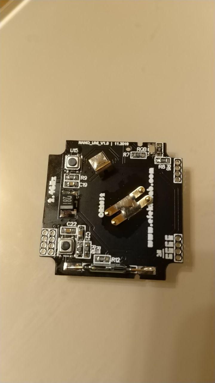
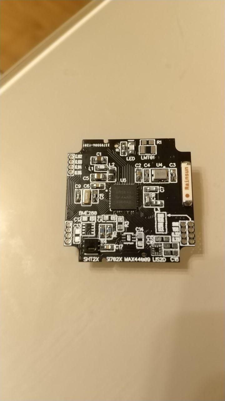
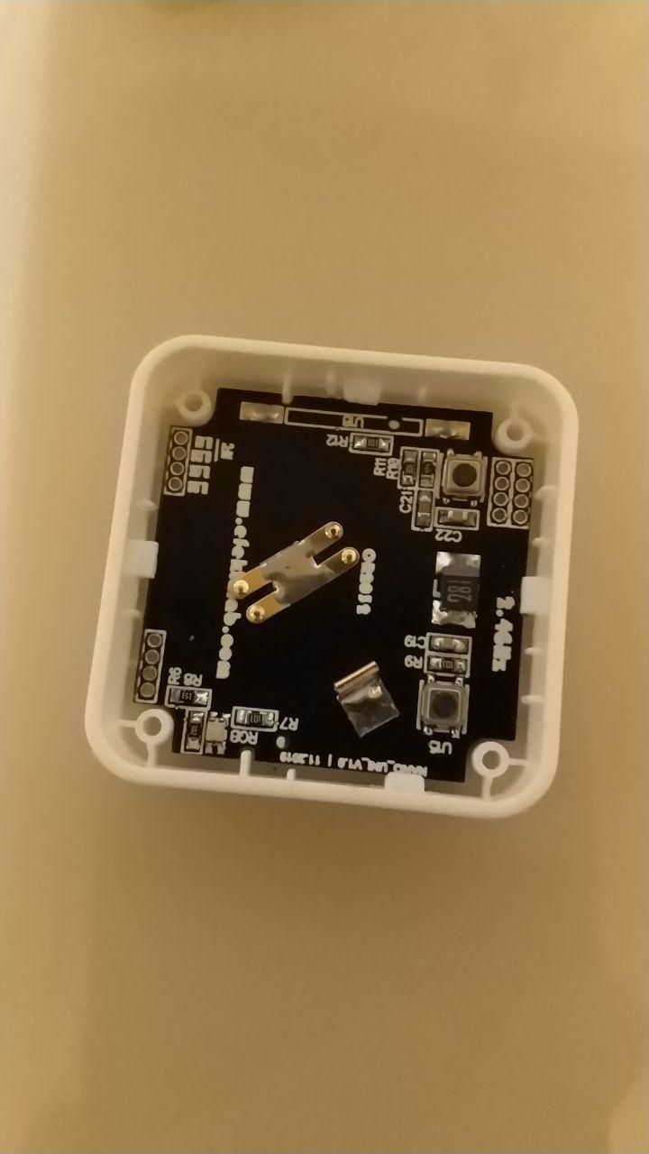
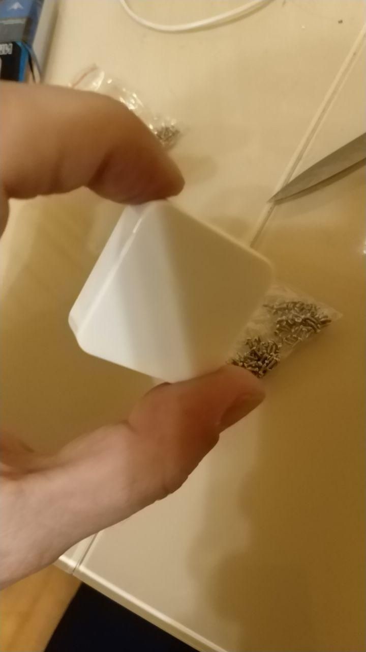
My new mini multi device on nRF52810, nRF52811, nRF52832 chips. Designed specifically for a very small case from Aliexpress. It works!!!
bme280, sht20/21, si7020/si7021, hdc1080, max40009, lis2dw12, lis2dh12, lmt01, reed switch, led + rgb led, user button and 6 analog pins, 6 digital pins with NFC.
VIDEO:
https://youtu.be/uxe9G3y720g -
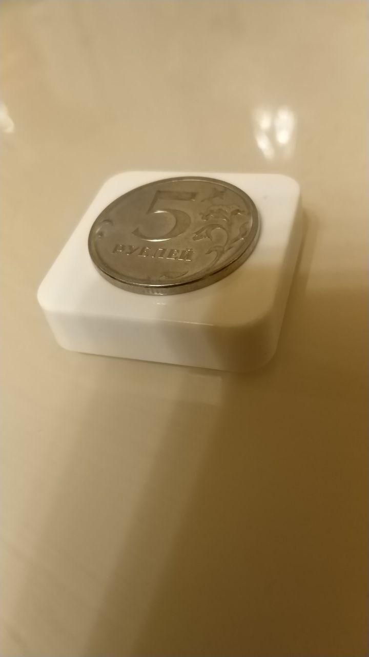
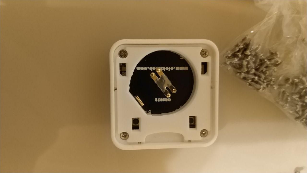
Today I designed a case for EasyPCB with 2xAA holder on the back.
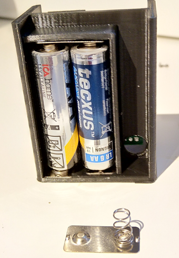
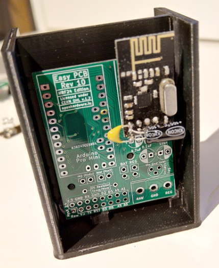
and a case that slides just over.
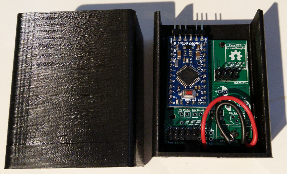
It works with 3x5 version so for this you accually have to use the more advanced option and reflash the fuses on your pro mini to make it 3x5. The normal EasyPCB with booster is 5x5, but Im thinking of just stretching this for another version.
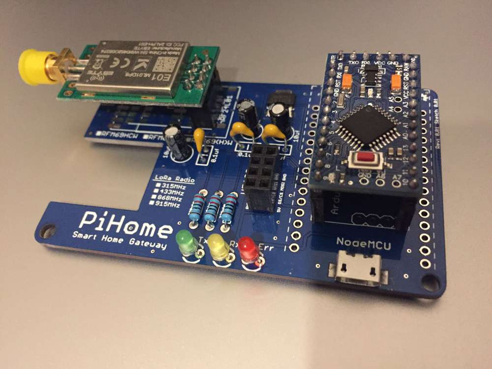
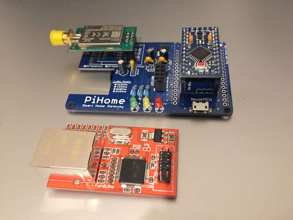
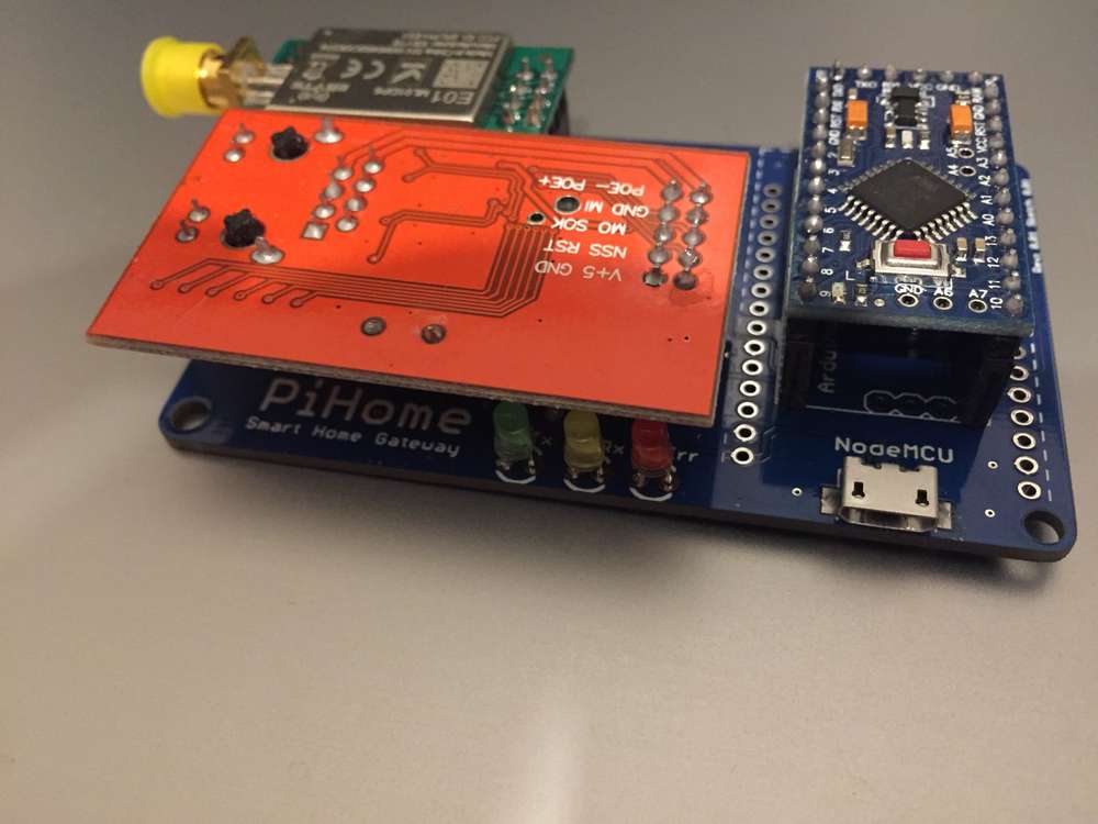
Controller: Proxmox VM - Home Assistant
MySensors GW: Arduino Uno - W5100 Ethernet, Gw Shield Nrf24l01+ 2,4Ghz
MySensors GW: Arduino Uno - Gw Shield RFM69, 433mhz
RFLink GW - Arduino Mega + RFLink Shield, 433mhz -
Today I designed a case for EasyPCB with 2xAA holder on the back.
and a case that slides just over.
It works with 3x5 version so for this you accually have to use the more advanced option and reflash the fuses on your pro mini to make it 3x5. The normal EasyPCB with booster is 5x5, but Im thinking of just stretching this for another version.
-
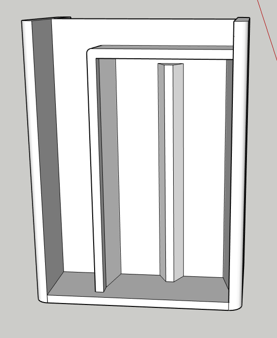
@sundberg84 just a suggestion; wouldn't it be good to move the batteries to the right (instead of the left) so they block the nrf antenna less?
@mfalkvidd - a great suggestion! It wont not block it completely but as you say, a little less.
-
Here's another idea too: if you were to add a blank copper cladded FR4 between the batteries and the PCB above it, with a cut-out below where the antenna is, then maybe you'd have a much improved ground plane, making your radio awesome? You could have little drawer like grooves on the side of your case to slide the copper cladded FR4 into position, and, of course, you would want a ground connection to it.
-
Not sure about that groundplane @NeverDie - you are most probably right but I dont really understand the theory behind it but sounds really cool!
Controller: Proxmox VM - Home Assistant
MySensors GW: Arduino Uno - W5100 Ethernet, Gw Shield Nrf24l01+ 2,4Ghz
MySensors GW: Arduino Uno - Gw Shield RFM69, 433mhz
RFLink GW - Arduino Mega + RFLink Shield, 433mhz -
Not sure about that groundplane @NeverDie - you are most probably right but I dont really understand the theory behind it but sounds really cool!
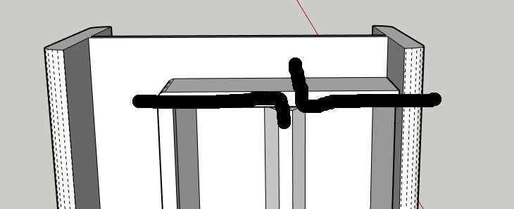
@sundberg84 Here's all the theory you need in one picture:

Most of the modules use a monopole antenna, and as near as I can tell, most of them, if not all of them, have insufficient ground plane. It still works, of course, but it's impaired over what it would be with a better ground plane. I think maybe that's why whenever someone switches to a dipole antenna they generally notice a huge improvement. So, there's always that, but your design is nice because it's so compact, and a dipole would spoil that. -
@sundberg84 Here's all the theory you need in one picture:
Most of the modules use a monopole antenna, and as near as I can tell, most of them, if not all of them, have insufficient ground plane. It still works, of course, but it's impaired over what it would be with a better ground plane. I think maybe that's why whenever someone switches to a dipole antenna they generally notice a huge improvement. So, there's always that, but your design is nice because it's so compact, and a dipole would spoil that.@NeverDie - so a ground plane like in here? Like that mod Pete did in his video but you inmplement it into the 3d case?
-
Yeah, the flat piece that the red line points to. I'm not sure what those black spray painted things are, so I'm ignoring those.
-
Made a dead-bug op-amp circuit to help measure open-circuit voltages created by nano-amp currents generated by a solar cell illuminated by just 1 lux of very dim light:
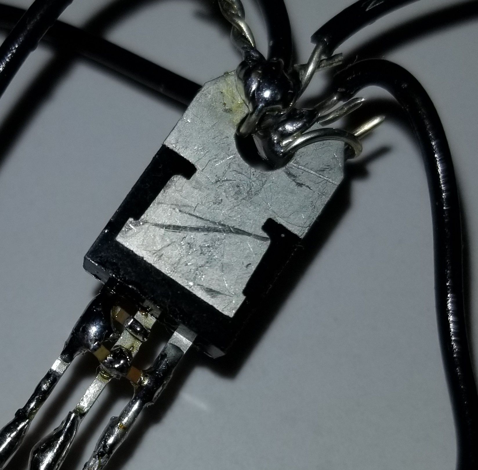
This picture is actually just the LDO part of the op-amp circuit, where I was able to solder the prescribed surface mount capacitors directly between its pins. The larger circuit is described on this thread: https://forum.mysensors.org/topic/10812/the-harvester-ultimate-power-supply-for-the-raybeacon-dk/122
Why dead-bug you ask? Since the circuit depends on the correct measurement of the effects of mere nanoamps, I didn't want any leakage currents that might happen on a protoboard, which can be significant when it's just a small number of nanoamps and their effects that's under scrutiny. -
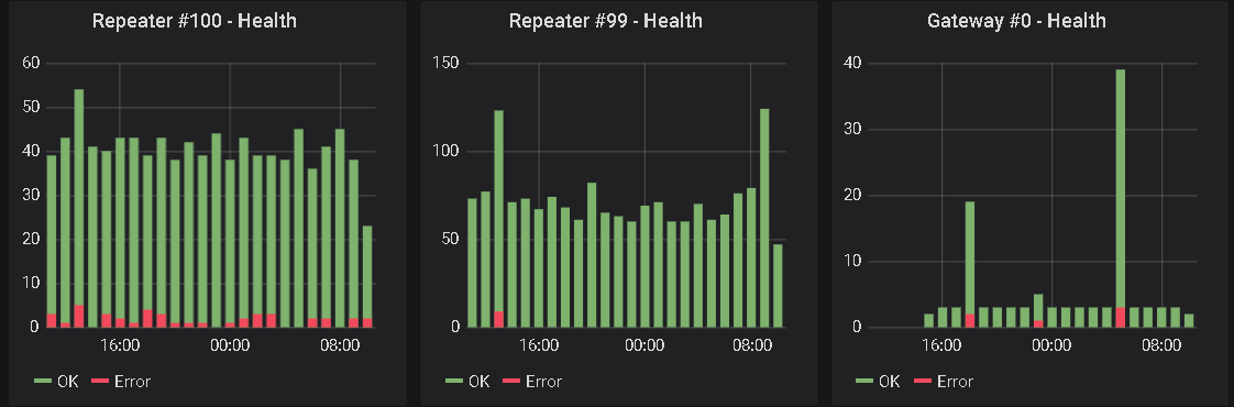
Updated my GW with the code @mfalkvidd provided to monitor OK and NACK
-
I got tired of twisting DuPont cabels to get from different programmers to different boards.
This is an adapter that lets me connect the programmers I commonly use (Jlink-mini, BMP, STLink clone) with the boards I commonly program with straight through wires. I left a couple unpopulated for future in and out.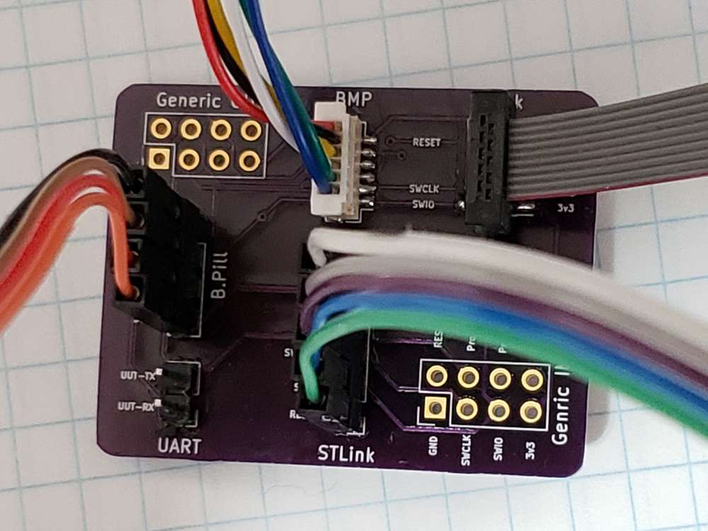
-
Finally I am starting to do a little electronics again.. First thing is a prototype assembly of RASLE (Rpi Arcade Sound and Light Extension). It's a custom made arduino "coprocessor" for a raspberry pi, built into retropie arcade cabinets. It's a joint project with a couple of friends that are building arcade cabinets (I built mine a couple of years ago, I think that there is pictures earlier in this thread).
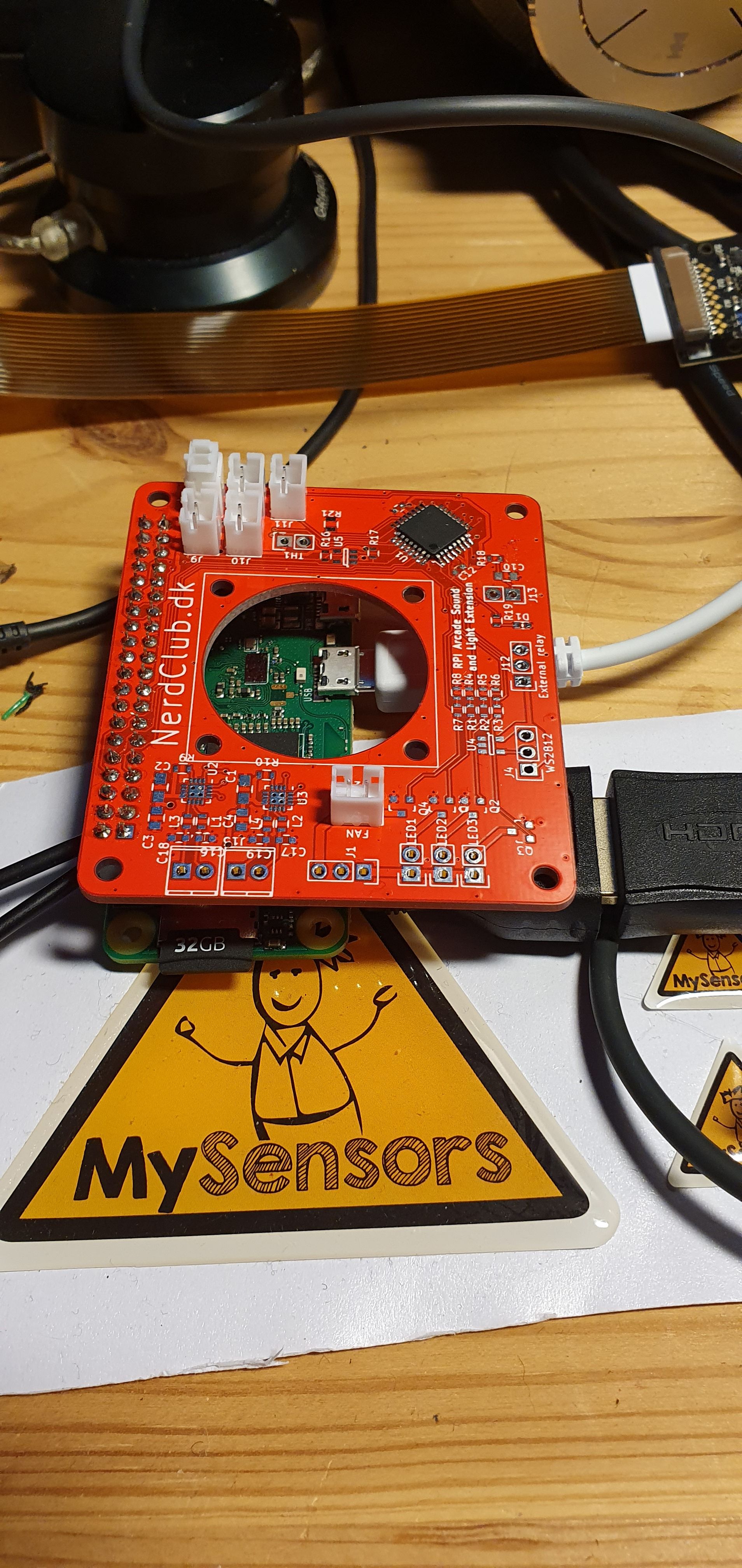
Features:
- stereo 3W class-d amplifier
- atmega328p
- 3 pwm channels for LED strips
- a port for WS2812 type led strips
- pwm channel for fan
- output for a relay to control mains input for the box (let the rpi shutdown cleanly, before disconnecting power)
- 5 button inputs (shared between rpi and atmega)
-
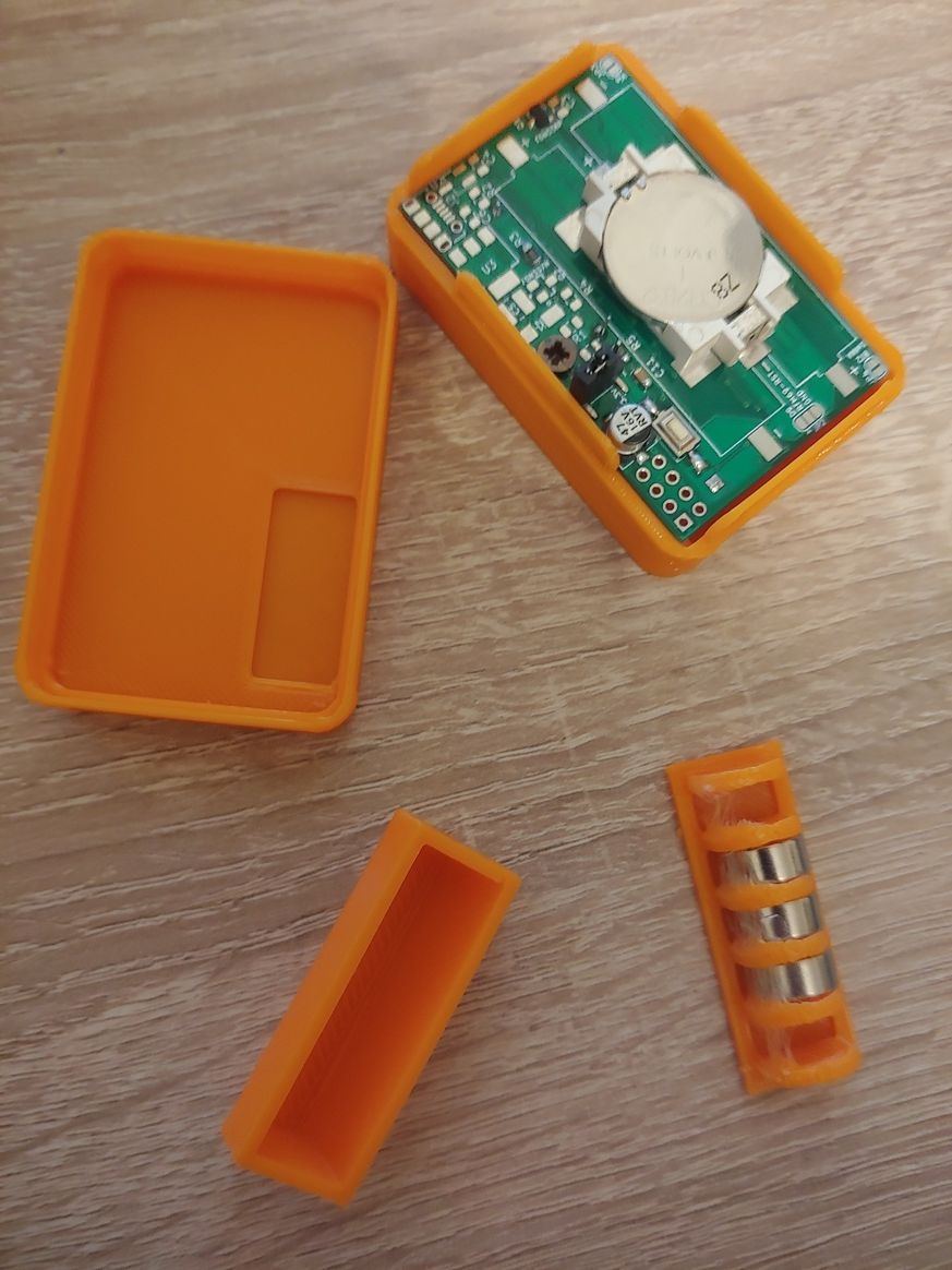
Hi, finished two nodes based on the same multi-purpose battery powered pcb (all the documentation here)
One is a door / window sensor based on a Reed switch.
If someone is interested, the dedicated wiki page contains the detailed build instructions.
The other is a soil moisture sensor.
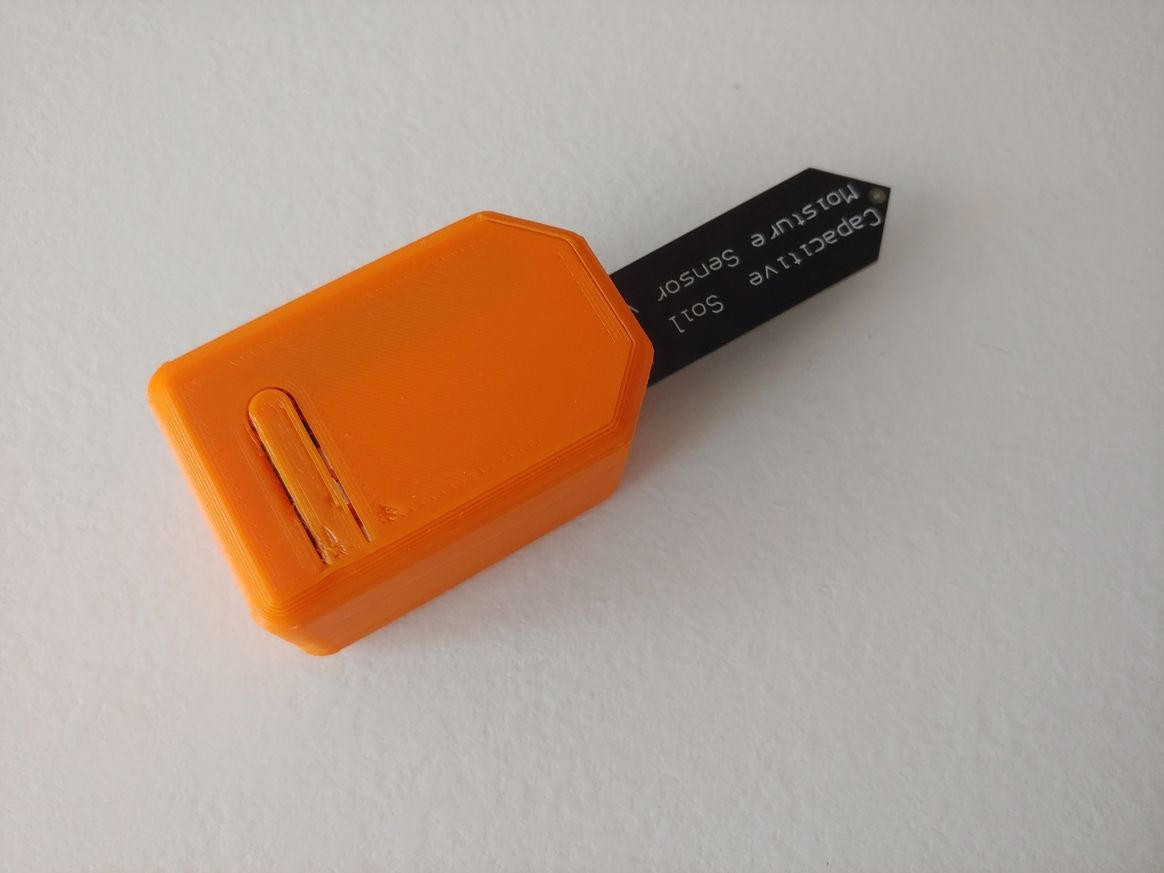
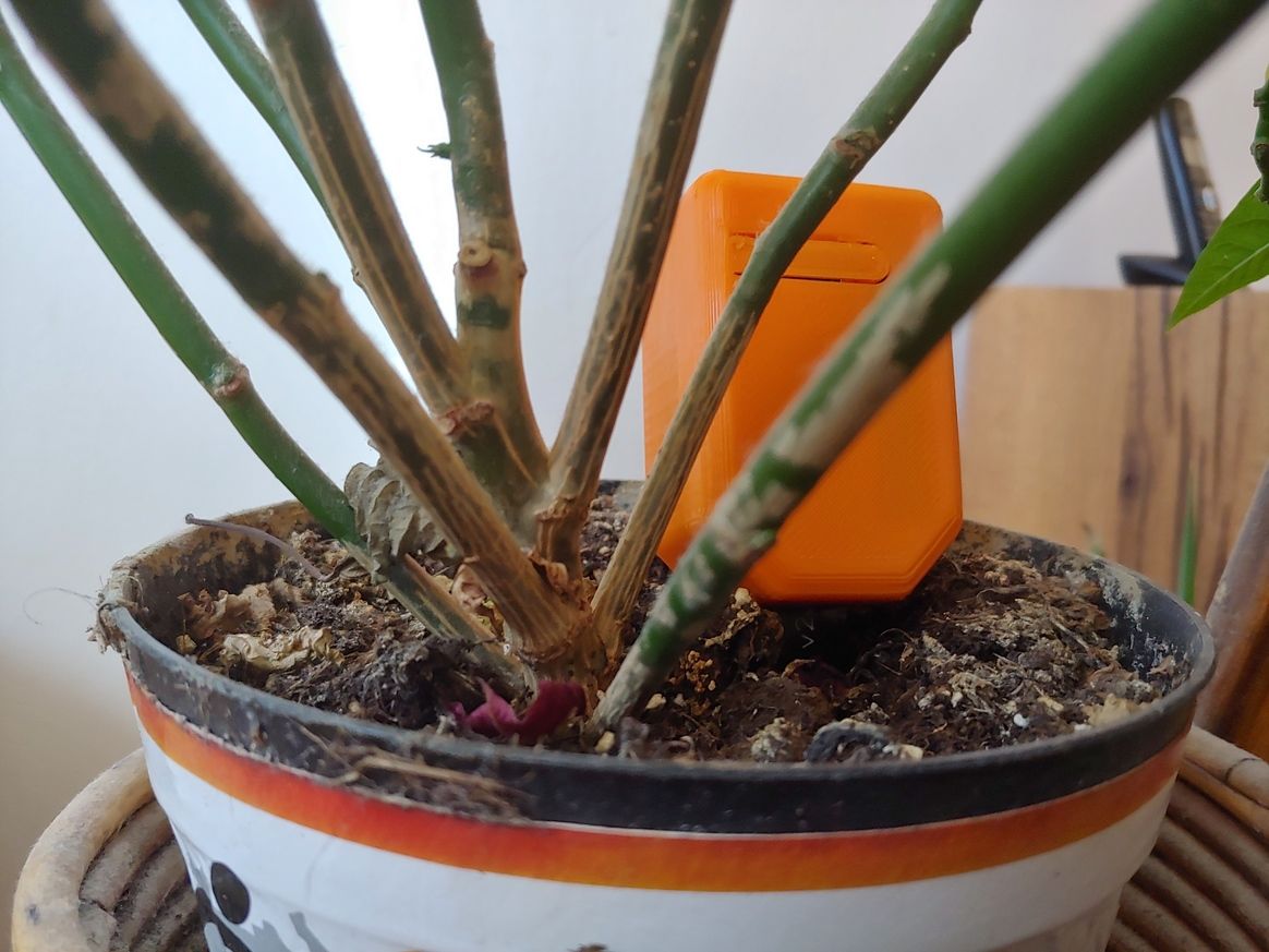
For this one, the wiki page is here.
Happy Easter, even if at home!