issues with light lux sensor and trinket pro
-
yes it is connected ok as other sensors do report to gw
what happens to A4 A5 they seem not to be given as a input or output
the trinket pro has available usb power but no pin D 2 or D 7.But it is reacting as though the trinket does not send info to gw
not quite sure how to debug this yet and still reading up and looking through forums
-
If the Trinklet has no D7 how did you connect the NRF24L01+ transceiver CSN/CS pin?
-
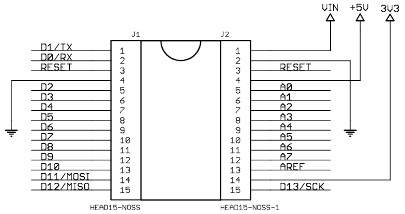
In my schematic of an Arduino Nano D7 is connected to pin 10 and http://www.mysensors.org/build/connect_radio is written with the Arduino Nano in mind:
-
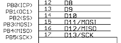
I think I am right, the port pins(? ) used for D9 toD13( the points where the DuPont wires are attached) are PB1 toPB5 which are the acual pins 13 to 17 on the ATmega (32 pin MLF) 328 chip on the Nano and Mini Pro which are the same chip pins on the Adafruit Trinket Pro.
The pins not available for use on the trinket pro are chip pins PD2 (INTO) and PD7 (AIN1)
so I think the wiring is ok .
-
From the same schematics I have of the same PB1 to PB5 mapping:
The pins not available for use on the trinket pro are chip pins PD2 (INTO) and PD7 (AIN1)
Above you mentioned D 2 and D 7 but indeed it looks like PD2 (INTO) and PD7 (AIN1) and these are also not connected on the Arduino Nano.
Did you have a look at the serial output of the sketch?
-
Did you have a look at the serial output of the Light Lux Sensor sketch on the Trinket?
-
I have the same question too... Pin A4 & A5 is not define in the sketch, but pin A0 is. How does the node know which pins to grab the values from? Are we not using Pin A4 & A5? and What happens to pin A0?
Hello! It looks like you're interested in this conversation, but you don't have an account yet.
Getting fed up of having to scroll through the same posts each visit? When you register for an account, you'll always come back to exactly where you were before, and choose to be notified of new replies (either via email, or push notification). You'll also be able to save bookmarks and upvote posts to show your appreciation to other community members.
With your input, this post could be even better 💗
Register Login