CNC PCB milling
-
@andrew said in CNC PCB milling:
do not forget to export the gerber settings before you upgrade the firmware, as it will loose those, and you have to re-assign the given values again, after the update.
Where are the gerber settings, and how do I export them? Are they in EEPROM, so I just do a complete copy of that? Or does the $$ handle it?
@NeverDie
firmware settings: it is stored in the EEPROM, but nothing guarantees that the same location will be used for the same parameters in case of different versions, so the output of "$$" command should be saved, this contains everything which you can manually set up if necessary.ER11: take extra care during the installation process to not "harm" the motor's axis. usually the ER11 is pretty tight and howtos mention that the motor should be cooled (by the freezer) and the ER11 should be warmed up before putting them together, to help the mounting process and to prevent unwanted distortion.
I put the CNC 2418 assembly guide to my share, for ones it is interesting.
-
@neverdie once the assembly is done, you should adjust the stepper drivers' current limiting as well.
it is pololu a4988, you can find the corresponding details here:
https://www.pololu.com/product/1182then, it is always good idea to have the basic settings exported from the board, just in case... you can do it by "$$" command sent from the g code sender gui or directly from the serial terminal.
currently I use the following settings, the machine might be able to create nice results with higher feed rates, but I did not have enough time to test it and I sticked to the current working config.
isolation routing with 2001 bits:
- z cut: -0.05mm
- feed rate: 200
you can calculate the V carving bit's tool width for the given milling depth with the following formula:
tan(bit angle/2) * milling depth * 2 + bit's end width
for excel formula the bit angle should be provided in radians, so it should look like this
tan(radians(bit angle/2)) * milling depth * 2 + bit's end widthedge cut or hole milling with the 0.8mm endmill:
- feed rate: 170
- z cut: -1.7mm
- multi depth, depth/pass: 0.2mm
drilling:
- feed rate: 130
- z cut: -1.8
the spindle should be 1000 everywhere.
most probably your board will not have a bootloader, so it will not be possible to update the firmware via usb serial connection (with avrdude), but it is worth to try it. for me it did not work, so I traced back the MCU pins to the pin rows and used ISP to upgrade the firmware to grbl v1.1f (the board will come with 0.9j if I remember correctly). do not forget to export the gerber settings before you upgrade the firmware, as it will loose those, and you have to re-assign the given values again, after the update.
the ISP pinout (from the pin row's top left corner):
Reset -> pin 2
SCK -> pin 3
MISO -> pin 12
MOSI -> pin 135v -> pin1
gnd-> bottom row(!) e.g. pin 1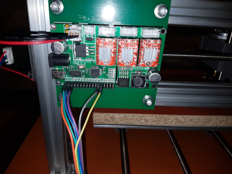
-
@rmtucker it is not 1000rpm, but the pwm control for the whole spindle speed range. see the details in the official document.
once you use the spindle speed with the value of $30 or above, then the controller will drive the spindle with continuous voltage, without pwm, so it will use its maximum rpm.
compared to bigger cncs with bigger spindles (e.g. what you can see from @executivul's video above) , 2418's is not that fast (in rpm), on the other hand it should not be "very slow". can you show a video on that? -
@NeverDie
firmware settings: it is stored in the EEPROM, but nothing guarantees that the same location will be used for the same parameters in case of different versions, so the output of "$$" command should be saved, this contains everything which you can manually set up if necessary.ER11: take extra care during the installation process to not "harm" the motor's axis. usually the ER11 is pretty tight and howtos mention that the motor should be cooled (by the freezer) and the ER11 should be warmed up before putting them together, to help the mounting process and to prevent unwanted distortion.
I put the CNC 2418 assembly guide to my share, for ones it is interesting.
@andrew said in CNC PCB milling:
I put the CNC 2418 assembly guide to my share, for ones it is interesting.
Yes, those are exactly the same instructions I received with my kit too.
-
@NeverDie
firmware settings: it is stored in the EEPROM, but nothing guarantees that the same location will be used for the same parameters in case of different versions, so the output of "$$" command should be saved, this contains everything which you can manually set up if necessary.ER11: take extra care during the installation process to not "harm" the motor's axis. usually the ER11 is pretty tight and howtos mention that the motor should be cooled (by the freezer) and the ER11 should be warmed up before putting them together, to help the mounting process and to prevent unwanted distortion.
I put the CNC 2418 assembly guide to my share, for ones it is interesting.
@andrew
I tried connecting to the Woodpecker board using the Arduino serial terminal at 115200 baud. It greets me by saying:Grbl 0.9j ['$' for help]However, if I send it $ I get no response. If I send it $$, I get no response either.
Is this normal?
How do I send it $$ and get it to respond?
-
@andrew
I tried connecting to the Woodpecker board using the Arduino serial terminal at 115200 baud. It greets me by saying:Grbl 0.9j ['$' for help]However, if I send it $ I get no response. If I send it $$, I get no response either.
Is this normal?
How do I send it $$ and get it to respond?
-
@andrew
I see.
So what would be your best guess at your actual spindle rpm when cutting under your feed/depth of cut examples given above.? -
Ah, nevermind. I changed the terminal to send it a carriage return, and now it works. Here is the output from asking it $ and $$:
Grbl 0.9j ['$' for help] $$ (view Grbl settings) $# (view # parameters) $G (view parser state) $I (view build info) $N (view startup blocks) $x=value (save Grbl setting) $Nx=line (save startup block) $C (check gcode mode) $X (kill alarm lock) $H (run homing cycle) ~ (cycle start) ! (feed hold) ? (current status) ctrl-x (reset Grbl) ok $0=10 (step pulse, usec) $1=25 (step idle delay, msec) $2=0 (step port invert mask:00000000) $3=5 (dir port invert mask:00000101) $4=0 (step enable invert, bool) $5=0 (limit pins invert, bool) $6=0 (probe pin invert, bool) $10=3 (status report mask:00000011) $11=0.010 (junction deviation, mm) $12=0.002 (arc tolerance, mm) $13=0 (report inches, bool) $20=0 (soft limits, bool) $21=0 (hard limits, bool) $22=0 (homing cycle, bool) $23=0 (homing dir invert mask:00000000) $24=25.000 (homing feed, mm/min) $25=500.000 (homing seek, mm/min) $26=250 (homing debounce, msec) $27=1.000 (homing pull-off, mm) $100=800.000 (x, step/mm) $101=800.000 (y, step/mm) $102=800.000 (z, step/mm) $110=5000.000 (x max rate, mm/min) $111=5000.000 (y max rate, mm/min) $112=800.000 (z max rate, mm/min) $120=10.000 (x accel, mm/sec^2) $121=10.000 (y accel, mm/sec^2) $122=10.000 (z accel, mm/sec^2) $130=200.000 (x max travel, mm) $131=200.000 (y max travel, mm) $132=200.000 (z max travel, mm) ok -
Here's the current build status:
I'm guessing I'm something more than half-way done. -
@NeverDie
firmware settings: it is stored in the EEPROM, but nothing guarantees that the same location will be used for the same parameters in case of different versions, so the output of "$$" command should be saved, this contains everything which you can manually set up if necessary.ER11: take extra care during the installation process to not "harm" the motor's axis. usually the ER11 is pretty tight and howtos mention that the motor should be cooled (by the freezer) and the ER11 should be warmed up before putting them together, to help the mounting process and to prevent unwanted distortion.
I put the CNC 2418 assembly guide to my share, for ones it is interesting.
@andrew said in CNC PCB milling:
the ER11 should be warmed up
how exactly? Heat gun?
I've put the motor assembly in the freezer....
-
Controller: Proxmox VM - Home Assistant
MySensors GW: Arduino Uno - W5100 Ethernet, Gw Shield Nrf24l01+ 2,4Ghz
MySensors GW: Arduino Uno - Gw Shield RFM69, 433mhz
RFLink GW - Arduino Mega + RFLink Shield, 433mhz -
@sundberg84 see andrew's earlier post.
Freezing the motor axis makes it a bit smaller.
-
@sundberg84 And heating up the other part makes it expand and get bigger allowing the two to fit together easier. Has to do with tight tolerances.
-
@andrew
Since I probably have only one shot at this, how hot should I heat up the ER11 before trying to fit it onto the frozen spindle? Should it be burning hot, or is luke-warm enough?@neverdie unfortunately, as I mentioned, I don't have ER11 (yet), and I just read articles and vendor suggestions on the installation method, so I cannot provide experience based suggestions to that. as far as I remember nor concrete temperature was mentioned, so I would say you should not "overheat" it.
-
@neverdie unfortunately, as I mentioned, I don't have ER11 (yet), and I just read articles and vendor suggestions on the installation method, so I cannot provide experience based suggestions to that. as far as I remember nor concrete temperature was mentioned, so I would say you should not "overheat" it.
@andrew said in CNC PCB milling:
@neverdie unfortunately, as I mentioned, I don't have ER11 (yet), and I just read articles and vendor suggestions on the installation method, so I cannot provide experience based suggestions to that. as far as I remember nor concrete temperature was mentioned, so I would say you should not "overheat" it.
I slipped it on, no problem at all. After freezing the motor overnight, what I did was heat the ER11 with my wife's crafting hot air gun. I held it with an insulated glove as I warmed it up. When it started to become uncomfortable to hold with even the insulated glove, I slipped it on without any resistance.
Hopefully this info will help you when you receive yours.
-
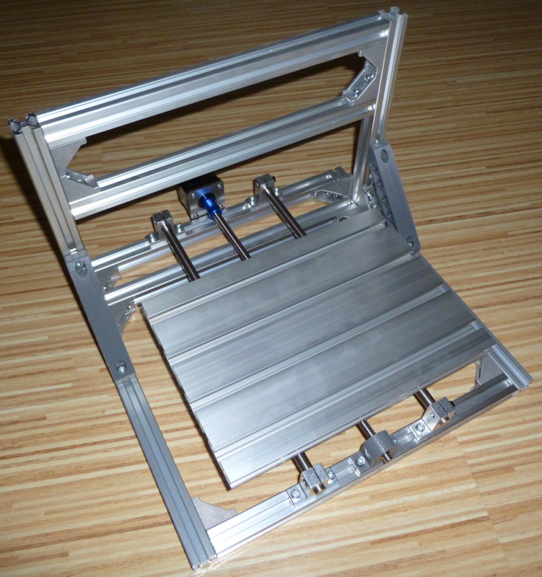
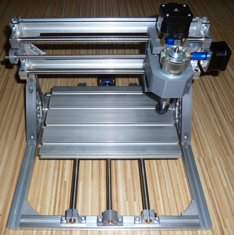
I seem to be finished with the mechanical assembly:
However, these washers came with the kit, and I'm not sure what they're for:
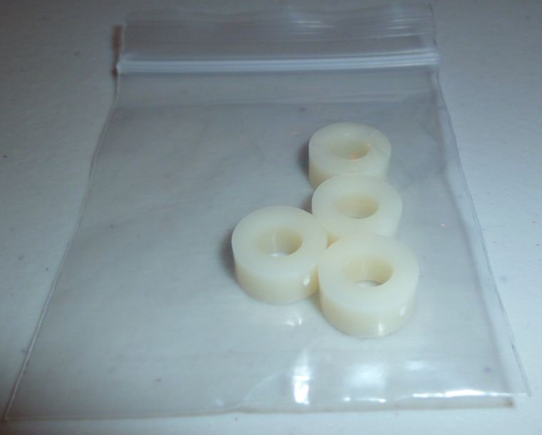
Anyone know? Are they for mounting the woodpecker board to the frame?Next I need to do the firmware upgrade and then wire things up.