CNC PCB milling
-
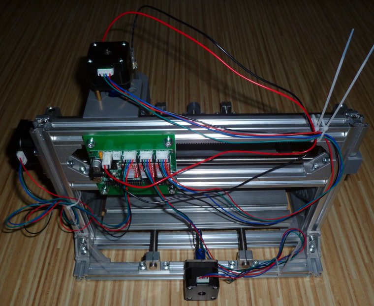
Done! Jack was certainly, uh, generous with the length of the wiring. I provisionally tacked it out of the way with the zip ties provided. I'll secure it better after I'm sure it's all working.
-
@neverdie the er-11 should be permanent. this spindle is not powerful enough to handle bigger tools and to mill harder materials.
you can start with grbl 0.9j, but it is worth to upgrade to 1.1f.
to the fw upgrade you can use a simple arduino as ISP programmer as well if you do not find your dragon.with chilipeppr (in case of grbl 0.9j go for http://chilipeppr.com/grbl , for 1.1.f go for http://chilipeppr.com/jpadie) you can quickly run its default logo engraving path for testing / demo purposes.
@andrew said in CNC PCB milling:
with chilipeppr (in case of grbl 0.9j go for http://chilipeppr.com/grbl , for 1.1.f go for http://chilipeppr.com/jpadie) you can quickly run its default logo engraving path for testing / demo purposes.
Thanks! That provided exactly what I was looking for. I ran the demo with no etching bit installed, and at first both X and Y seemed to be working, but the adapter coupling eventually loosened on both of them to the point where there was no longer X and Y movement. I've re-tightened tem, and it's working again. I hope it lasts.
Not sure where I should go next from here though.
-
@andrew said in CNC PCB milling:
with chilipeppr (in case of grbl 0.9j go for http://chilipeppr.com/grbl , for 1.1.f go for http://chilipeppr.com/jpadie) you can quickly run its default logo engraving path for testing / demo purposes.
Thanks! That provided exactly what I was looking for. I ran the demo with no etching bit installed, and at first both X and Y seemed to be working, but the adapter coupling eventually loosened on both of them to the point where there was no longer X and Y movement. I've re-tightened tem, and it's working again. I hope it lasts.
Not sure where I should go next from here though.
@neverdie said in CNC PCB milling:
@andrew said in CNC PCB milling:
with chilipeppr (in case of grbl 0.9j go for http://chilipeppr.com/grbl , for 1.1.f go for http://chilipeppr.com/jpadie) you can quickly run its default logo engraving path for testing / demo purposes.
Thanks! That provided exactly what I was looking for. I ran the demo with no etching bit installed, and at first both X and Y seemed to be working, but the adapter coupling eventually loosened on both of them to the point where there was no longer X and Y movement. I've re-tightened tem, and it's working again. I hope it lasts.
Not sure where I should go next from here though.
so, as this machine does not have limit switches installed, it is your responsibility to move the gantry to a position, from where you would like to start the job and which provides enough space for each direction movement. usually you have to set a relative zero at the given starting point.
what is next? did you adjusted the stepper drivers? if not, then do it (I shared the link above). this is necessary to be sure, that the steppers will be powered with enough current (so they will be powerful enough for the given speed related movement and to provide enough force) or will not be overdriven.
then, I would say try to engrave the chilipeppr logo to a soft material first, have some experience with the cnc.
then, as I mentioned, discover the flatcam tool and try to create an isolation routing job for a test pcb.
I already mentioned my confirmed settings for the given jobs (edge / hole milling, isolation routing).
you should sacrifice some boards for your experience :)also, try to find your ideal g code sender tool by trying multiple ones.
-
I don't see any plugs on the woodpecker board that are designated for connecting to a touch plate. So, I guess it's configured using the woodpecker header pins? How is that best set up?
By the way, after re-tightening the set-screws on the adapters used to connect the step-motors to the screw rods, they seem to be holding now and not slipping loose.I take it back, one of them just came loose again. :( -
I don't see any plugs on the woodpecker board that are designated for connecting to a touch plate. So, I guess it's configured using the woodpecker header pins? How is that best set up?
By the way, after re-tightening the set-screws on the adapters used to connect the step-motors to the screw rods, they seem to be holding now and not slipping loose.I take it back, one of them just came loose again. :(@neverdie said in CNC PCB milling:
one of them just came loose again
And now the other one did too. Is anyone using a threadlocker on the set screws to keep this from happening?
I think I'll put on some locktite and let it dry overnight and then see if it still happens tomorrow. I'll start with just the threaded rods.
Anyhow, the good news is that the heat sinks plainly did not short out the GRBL controller boards. I guess the adhesive must act as an electrical insulator.
-
Thinking about it now, an alternative might be to grind one side of the threaded rod flat in the region where it fits into the adapter. That would match the concept of the motor rotor, where that has already been done.
Ideally I would notch it in just the region where the set screw makes contact. I suppose I could do that with a Dremel.
Investigating now, I see that the adapter came loose on the motor rotor also. So, I think locktite will be a must.
http://www.loctiteproducts.com/tds/T_LKR_BLUE_tds.pdf
Looking at the datasheet, it takes 24 hours to cure.
-
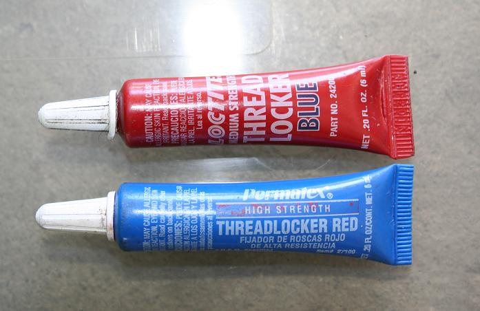
Well, humbug! I'm all out. Maybe tomorrow I'll buy the red threadlocker, which is even stronger.
@neverdie, or anyone else that can answer this with some logic, just because the topic came up. Why does Loctite red come in a blue container and loctite blue come in a red container?
Vera Plus running UI7 with MySensors, Sonoffs and 1-Wire devices
Visit my website for more Bits, Bytes and Ramblings from me: http://dan.bemowski.info/ -
@neverdie, or anyone else that can answer this with some logic, just because the topic came up. Why does Loctite red come in a blue container and loctite blue come in a red container?
-
Probably historical reasons.
-
@dbemowsk said in CNC PCB milling:
Why does Loctite red come in a blue container and loctite blue come in a red container?
Made in China?
-
I don't see any plugs on the woodpecker board that are designated for connecting to a touch plate. So, I guess it's configured using the woodpecker header pins? How is that best set up?
By the way, after re-tightening the set-screws on the adapters used to connect the step-motors to the screw rods, they seem to be holding now and not slipping loose.I take it back, one of them just came loose again. :(@neverdie for the touch sensing you should use A5 connector from the headers, connecting it to the actual tool (bit), then a gnd (header's bottom row) connecting to the pcb's surface.
for the tool connection I use crocodile clamps.
screws: you did not fasten them enough. at the beginning I also missed some endpoints, but since I put the cnc together, I had no issue with any of my screws.
-
@neverdie for the touch sensing you should use A5 connector from the headers, connecting it to the actual tool (bit), then a gnd (header's bottom row) connecting to the pcb's surface.
for the tool connection I use crocodile clamps.
screws: you did not fasten them enough. at the beginning I also missed some endpoints, but since I put the cnc together, I had no issue with any of my screws.
@andrew for first go for a single touch probing instead of a whole autoleveling session.
just for testing purposes, start the touch probing from a higher position and touch the gnd wire directly to the spindle's tool to see whether it stops or not. if not, you should stop it manually from the gui, otherwise it could break the tool.
if everything works well (so you proved that you connections to the pins and the belonging settings are ok), then you can run the simple touch probes or the autoleveling as well. -
@neverdie said in CNC PCB milling:
one of them just came loose again
And now the other one did too. Is anyone using a threadlocker on the set screws to keep this from happening?
I think I'll put on some locktite and let it dry overnight and then see if it still happens tomorrow. I'll start with just the threaded rods.
Anyhow, the good news is that the heat sinks plainly did not short out the GRBL controller boards. I guess the adhesive must act as an electrical insulator.
@neverdie said in CNC PCB milling:
Is anyone using a threadlocker on the set screws to keep this from happening?
For one that will probably buy the same CNC could you document how you solve this with a picture?
-
Probably a committee decision. Half liked red, and the other half liked blue. They were deadlocked, and this was their compromise decision. :laughing:
-
@neverdie for the touch sensing you should use A5 connector from the headers, connecting it to the actual tool (bit), then a gnd (header's bottom row) connecting to the pcb's surface.
for the tool connection I use crocodile clamps.
screws: you did not fasten them enough. at the beginning I also missed some endpoints, but since I put the cnc together, I had no issue with any of my screws.
@andrew said in CNC PCB milling:
you should use A5 connector
Does using A5 somehow automagically just work, or does it require additional software configuration?