CNC PCB milling
-
@executivul I do manual leveling and I rarely have to level the bed itself.
@dbemowsk said in CNC PCB milling:
@executivul I do manual leveling and I rarely have to level the bed itself.
"If it works don't break it!"
To end the offtopic, for anybody interested RepRap forum piezo discussion and https://www.precisionpiezo.co.uk/ the store of the guys who brought the piezo to the world, there are 1:1 clones on aliexpress, but the price is almost the same if you buy only the board and print your own holder and they provide warranty, fast shipping and are really great people so they deserve some support! (I'm not affiliated in any way to their store)
LE. @NeverDie if you read this please look up 4-5 posts and tell me if your gcode has the autoleveling
-
@dbemowsk said in CNC PCB milling:
@executivul I do manual leveling and I rarely have to level the bed itself.
"If it works don't break it!"
To end the offtopic, for anybody interested RepRap forum piezo discussion and https://www.precisionpiezo.co.uk/ the store of the guys who brought the piezo to the world, there are 1:1 clones on aliexpress, but the price is almost the same if you buy only the board and print your own holder and they provide warranty, fast shipping and are really great people so they deserve some support! (I'm not affiliated in any way to their store)
LE. @NeverDie if you read this please look up 4-5 posts and tell me if your gcode has the autoleveling
@executivul said in CNC PCB milling:
if you read this please look up 4-5 posts and tell me if your gcode has the autoleveling
yes. In Chilipeppr I send the autoleveling to the workspace, at which point it modifies the gcode.
-
@neverdie for pcb milling a small height difference across the board's area could result in a big negative effect if autoleveling is not performed properly.
I would double check your autoleveling process, on the other hand, you could also try to use bed flattening with a bigger endmill tool first, then place the pcb to the flattened area. this could help you to eliminate or decrease the cnc assembly or the sacrificial board caused roughness.for further details please see the following link:
http://flatcam.org/manual/procedures.html#bed-flattening@andrew said in CNC PCB milling:
@neverdie for pcb milling a small height difference across the board's area could result in a big negative effect if autoleveling is not performed properly.
I would double check your autoleveling process, on the other hand, you could also try to use bed flattening with a bigger endmill tool first, then place the pcb to the flattened area. this could help you to eliminate or decrease the cnc assembly or the sacrificial board caused roughness.for further details please see the following link:
http://flatcam.org/manual/procedures.html#bed-flatteningWhat's the best type of sacrifice board to use if doing bed flattening? Regular wood, or should I stick with particle board or MDF?
-
It seems the z-height only needs to be off by a small amount (say 0.02mm) to have a noticeably negative effect on the trace width.
-
@dbemowsk said in CNC PCB milling:
@executivul I do manual leveling and I rarely have to level the bed itself.
"If it works don't break it!"
To end the offtopic, for anybody interested RepRap forum piezo discussion and https://www.precisionpiezo.co.uk/ the store of the guys who brought the piezo to the world, there are 1:1 clones on aliexpress, but the price is almost the same if you buy only the board and print your own holder and they provide warranty, fast shipping and are really great people so they deserve some support! (I'm not affiliated in any way to their store)
LE. @NeverDie if you read this please look up 4-5 posts and tell me if your gcode has the autoleveling
-
@andrew said in CNC PCB milling:
@neverdie for pcb milling a small height difference across the board's area could result in a big negative effect if autoleveling is not performed properly.
I would double check your autoleveling process, on the other hand, you could also try to use bed flattening with a bigger endmill tool first, then place the pcb to the flattened area. this could help you to eliminate or decrease the cnc assembly or the sacrificial board caused roughness.for further details please see the following link:
http://flatcam.org/manual/procedures.html#bed-flatteningWhat's the best type of sacrifice board to use if doing bed flattening? Regular wood, or should I stick with particle board or MDF?
@neverdie said in CNC PCB milling:
What's the best type of sacrifice board to use if doing bed flattening? Regular wood, or should I stick with particle board or MDF?
I never had to try it, so I don't know. for me the regular wood seems to be logical...
-
@andrew said in CNC PCB milling:
@neverdie for pcb milling a small height difference across the board's area could result in a big negative effect if autoleveling is not performed properly.
I would double check your autoleveling process, on the other hand, you could also try to use bed flattening with a bigger endmill tool first, then place the pcb to the flattened area. this could help you to eliminate or decrease the cnc assembly or the sacrificial board caused roughness.for further details please see the following link:
http://flatcam.org/manual/procedures.html#bed-flatteningWhat's the best type of sacrifice board to use if doing bed flattening? Regular wood, or should I stick with particle board or MDF?
@neverdie Sorry @andrew, wood is not a stable material, it is not inert and changes shape, it breathes if you will.
Artificial materials such as particle board or MDF have a stable matrix, but of the two, MDF is the more uniform and least reactive, hence it's popularity for kitchen cupboards, loudspeaker cases, etc..
It is easily machined, but is hard on the typical router bits, although nowhere near that of HDF.The bigger problem with mdf is the very fine dust produced when milling or cutting it with power tools, it gets everywhere, including your lungs, and can even get through vacuum cleaners without hepa filters....
I would suggest either a thick MDF or layers glued together, cut the sides to requirements, lock it in place and set a 6 or 8mm router bit for MDF in a collet, and set it to work, ideally outside where you can hose it down after sweeping up and vacuuming.
-
I think there may be some kind of coating that comes on these PCB's. Maybe it's to prevent corrosion of the copper? It seems to come off using IPA. Here one is before cleaning with IPA:
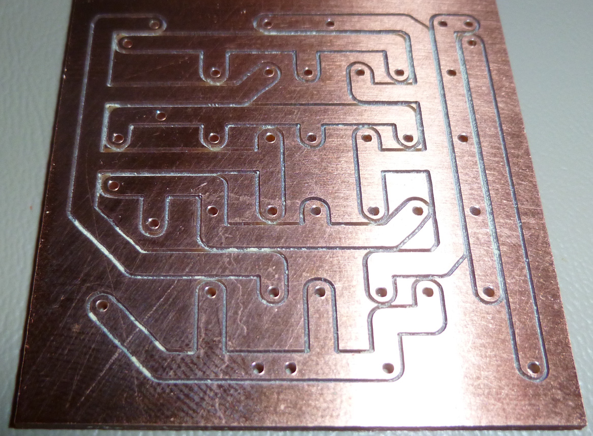
And here is the same PCB after cleaning with IPA:
Not sure whether it interferes with soldering. Anyone know? For now I'm cleaning it off. -
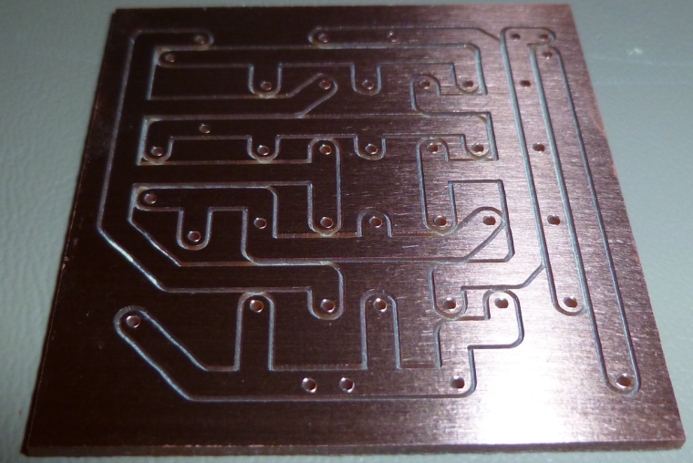
I think there may be some kind of coating that comes on these PCB's. Maybe it's to prevent corrosion of the copper? It seems to come off using IPA. Here one is before cleaning with IPA:
And here is the same PCB after cleaning with IPA:
Not sure whether it interferes with soldering. Anyone know? For now I'm cleaning it off. -
So a CNC question as I build my prototype machine. I have an arduino with CNC shield on order that should arrive tomorrow. My question is, does this allow for a display and keypad for local control or is everything just done through GRBL?
https://www.amazon.com/SODIAL-Arduino-Compatible-DRV8825-StepStick/dp/B074FVTTR7/ref=sr_1_7?s=electronics&ie=UTF8&qid=1517499916&sr=1-7&keywords=arduino+uno+cnc -
So a CNC question as I build my prototype machine. I have an arduino with CNC shield on order that should arrive tomorrow. My question is, does this allow for a display and keypad for local control or is everything just done through GRBL?
https://www.amazon.com/SODIAL-Arduino-Compatible-DRV8825-StepStick/dp/B074FVTTR7/ref=sr_1_7?s=electronics&ie=UTF8&qid=1517499916&sr=1-7&keywords=arduino+uno+cncAll done via GCodeSender and similar i'm afraid... which is not a problem as far as i can see
Your Arduino is fully populated with this board :
- driving stepper drivers
- end-stops
- coolant (or wathever) enable
- spindle control (speed and rotation) (V3 shield can do PWM control if your spindle driver can). Be aware that this board doesn't drive any kind of motor. Just sends signal
- cloning axis of your choice
- emergency stop, pause and resume
- i might forget some details but i'm sure you get the point
But it's a pretty cool board for veeeery reasonable price. I love it !
-
All done via GCodeSender and similar i'm afraid... which is not a problem as far as i can see
Your Arduino is fully populated with this board :
- driving stepper drivers
- end-stops
- coolant (or wathever) enable
- spindle control (speed and rotation) (V3 shield can do PWM control if your spindle driver can). Be aware that this board doesn't drive any kind of motor. Just sends signal
- cloning axis of your choice
- emergency stop, pause and resume
- i might forget some details but i'm sure you get the point
But it's a pretty cool board for veeeery reasonable price. I love it !
@ben999 So reading through your specs, everything seems pretty straight forward. I get that the spindle motor will need it's own controller which can be driven by the CNC board. One thing I am confused on though, what is "cloning axis of your choice". I am new to CNC.
-
@ben999 So reading through your specs, everything seems pretty straight forward. I get that the spindle motor will need it's own controller which can be driven by the CNC board. One thing I am confused on though, what is "cloning axis of your choice". I am new to CNC.
@dbemowsk this board can accept up to 4 stepper drivers
your machine is probably a 3-axis CNC, so in most cases one stepper per axis could do the trick.
BUT sometimes some CNC designs require a 2nd stepper for an axis (usually the x-axis). Then add a 4th driver and some jumpers and you're done. You end up with 2 steppers doing exactly the same job
-
So I received my CNC board today. After looking over the board, I see that it has 2 endstop points per axis. Logical assumption would be that there would be one on each end of travel of an axis. I was a bit confused because my 3D printer only has 1 per axis. Do I need to use both for each axis when running GRBL?
-
So today I decided to do a little bit of testing with the CNC shield and my Y axis drive. To start off, one of the issues I have is that I do not know the specs of the motor that I have. Here is a pic:
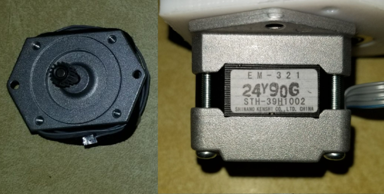
Did quite a bit of searching over the past week to try and find any information, and I can't seem to find what I need. I decided to do some tests anyway. I was able to get GRBL loaded on to the UNO board fine and connect to it through PUTTY. I then installed just the Y axis driver and connected a 12 volt power supply for starters. I was able to get the Y axis screw turning by sending some Y axis commands such as "Y20" or "Y-20". When I ran it initially I didn't have the Y axis platter mount secured to anything, so that would just spin with the screw. The problem I have is that if I hold the platter mount giving the screw even the slightest bit of resistance, the motor will spin for half a second and then start making a whining/buzzing noise and will just vibrate a bit. Once the motor starts to slow down while stopping, the screw will stop whining and spin slightly at the end of the stop. I then thought that it might be that the voltage was too low as I had read on some forums about some Epson steppers being higher voltage steppers, so I connected a 30 volt supply. Running the same test gave me the same results. Does anyone have a clue as to why this would happen? Basically the motor doesn't have any torque. -
So today I decided to do a little bit of testing with the CNC shield and my Y axis drive. To start off, one of the issues I have is that I do not know the specs of the motor that I have. Here is a pic:
Did quite a bit of searching over the past week to try and find any information, and I can't seem to find what I need. I decided to do some tests anyway. I was able to get GRBL loaded on to the UNO board fine and connect to it through PUTTY. I then installed just the Y axis driver and connected a 12 volt power supply for starters. I was able to get the Y axis screw turning by sending some Y axis commands such as "Y20" or "Y-20". When I ran it initially I didn't have the Y axis platter mount secured to anything, so that would just spin with the screw. The problem I have is that if I hold the platter mount giving the screw even the slightest bit of resistance, the motor will spin for half a second and then start making a whining/buzzing noise and will just vibrate a bit. Once the motor starts to slow down while stopping, the screw will stop whining and spin slightly at the end of the stop. I then thought that it might be that the voltage was too low as I had read on some forums about some Epson steppers being higher voltage steppers, so I connected a 30 volt supply. Running the same test gave me the same results. Does anyone have a clue as to why this would happen? Basically the motor doesn't have any torque.@dbemowsk current gets you torque, voltage gets you speed. What driver do you use? See the current setting for the driver you use, how/what voltage you measure to determine the current and the formula that links the two.
When I want to set the sweetspot (assuming driver and stepper are somewhat matched) I start low and increase the current little by little until the stepper gets warm after a few minutes. Warm, not hot! But again, the driver and stepper must match, I wouldn't try that with a Pololu A4988 and a Nema 34 stepper 😂
-
@dbemowsk current gets you torque, voltage gets you speed. What driver do you use? See the current setting for the driver you use, how/what voltage you measure to determine the current and the formula that links the two.
When I want to set the sweetspot (assuming driver and stepper are somewhat matched) I start low and increase the current little by little until the stepper gets warm after a few minutes. Warm, not hot! But again, the driver and stepper must match, I wouldn't try that with a Pololu A4988 and a Nema 34 stepper 😂
-
@dbemowsk well then check the current set by measuring Vref, plenty of tutorials on the web. If it's lower than 500mA try bumping it up little by little. Also try reducing the microsteps to 16 or 8 by removing jumpers.
Hello! It looks like you're interested in this conversation, but you don't have an account yet.
Getting fed up of having to scroll through the same posts each visit? When you register for an account, you'll always come back to exactly where you were before, and choose to be notified of new replies (either via email, or push notification). You'll also be able to save bookmarks and upvote posts to show your appreciation to other community members.
With your input, this post could be even better 💗
Register Login