💬 Wireless Touch Switch: Relay Model - (For Livolo crystals)
-
-
is i t working model
-
@giridhararm said in 💬 Wireless Touch Switch: Relay Model - (For Livolo crystals):
is i t working model
The PCBs are not finished, I still have to try the signature chip and the flash chip, I also need to try the RF communication using the MySensor library, with other libraries it has worked well so I do not expect surprises at that point.
I'm waiting for the MDMSGate gateway to arrive to finish the tests, and the new angled connectors to make the PCBs again.
Except for those points that need to be tested, everything else works correctly. Now I'm going to make the new box, it will look like this:

-
Very nice. Thanks for Sharing!
-
Today I received the Gateway MDMSGate and the touch switch works correctly, interacting with all the sensors of the node. This afternoon I will try the FOTA updates.

-
I can not update the sketch by FOTA. The MYSController program connects to the node and sends the .hex, the debug node shows that it is receiving it ... but at the end it continues executing the same code as at the beginning, the new code does not apply.
I have recorded the SenseBender Micro bootloader as it says on this page.
I am using the W25X40CLSNIG flash chip that I have read is compatible.
This is the electrical diagram:
https://www.openhardware.io/dl/5a5cfa51f275ddd3122ea462/design/Touch Switch.pdfIn the sketch I have defined the following constants:
//Pinout Touch Switch Board V2.1 and Relay Switch Board V1.1
#define pFLASH_SS  A0

//MySensor configuration:
#define MY_OTA_FIRMWARE_FEATURE                 // Define this in sketch to allow safe over-the-air firmware updates
#define MY_OTA_FLASH_SS             pFLASH_SS   // Slave select pin for external flash.
#define MY_OTA_FLASH_JDECID         0xEF30      // https://forum.mysensors.org/topic/4267/w25x40clsnig-as-flash-for-ota
This is the complete code:
/**
 * Name:     Smarthome: Touch Switch Two Light (MySensors)
 * Autor:    Alberto Gil Tesa
 * Web:      https://giltesa.com/?p=18460
 * License:  CC BY-NC-SA 3.0
 * Version:  1.0
 * Date:     2018/01/13
 *
 */


/**
 *  Pinout Touch Switch Board V2.1 and Relay Switch Board V1.1
 */
#define pBTN        2 //Interruption
#define pZERO       3 //Interruption (Not used)
#define pLED_BLUE   4
#define pRELAY_1    5 //PWM
#define pRELAY_2    6 //PWM
#define pNRF_CE     7
#define pNRF_CSN    8
#define pLED_RED    9 //PWM
#define pLED_GREEN 10 //PWM
#define pFLASH_SS  A0
#define pDS18B20   A1
#define pATSHA204A A3


/**
 * MySensor configuration:
 */
#define MY_DEBUG                                // Enable debug prints to serial monitor
#define MY_BAUD_RATE                9600        // Serial output baud rate
#define MY_TRANSPORT_WAIT_READY_MS  1           // Set how long to wait for transport ready in milliseconds
#define MY_RADIO_NRF24                          // Enable and select radio type attached
#define MY_RF24_CE_PIN              pNRF_CE     // Define this to change the chip enable pin from the default
#define MY_RF24_CS_PIN              pNRF_CSN    // Define this to change the chip select pin from the default
//#define MY_REPEATER_FEATURE                   // Enable repeater functionality for this node
#define MY_OTA_FIRMWARE_FEATURE                 // Define this in sketch to allow safe over-the-air firmware updates
#define MY_OTA_FLASH_SS             pFLASH_SS   // Slave select pin for external flash.
#define MY_OTA_FLASH_JDECID         0xEF30      // https://forum.mysensors.org/topic/4267/w25x40clsnig-as-flash-for-ota

#define MS_BOARD_NAME               "Touch Switch: Two light"
#define MS_SOFTWARE_VERSION         "1.0"
#define MS_RELAY1_CHILD_ID          0
#define MS_RELAY2_CHILD_ID          1
#define MS_LEDPWM_CHILD_ID          2
#define MS_TEMP_CHILD_ID            3

#include <MySensors.h>
#include <OneWire.h>
#include <DallasTemperature.h>
#include <AsyncTaskLib.h>

MyMessage msgR1(MS_RELAY1_CHILD_ID, V_TRIPPED);
MyMessage msgR2(MS_RELAY2_CHILD_ID, V_TRIPPED);
MyMessage msgT1(MS_TEMP_CHILD_ID,   V_TEMP);

OneWire oneWire(pDS18B20);
DallasTemperature ds18b20(&oneWire);

AsyncTask *taskOn, *taskOff;
byte brightnessLed = 255;

         const  unsigned long tDebouncePress = 50;
         const  unsigned long tWaitTwoPress  = 400;
         const  unsigned long tShortPress    = 300;
volatile static unsigned long tBtnPressed1   = 0;
volatile static unsigned long tBtn1Released1 = 0;
volatile static unsigned long tBtnPressed2   = 0;
volatile static unsigned long tBtn1Released2 = 0;
         static boolean       sBtnPressed    = false;


/**
 * For initialisations that needs to take place before MySensors transport has been setup (eg: SPI devices).
 */
void before()
{
    pinMode(pBTN,       INPUT);
    pinMode(pLED_RED,   OUTPUT);
    pinMode(pLED_GREEN, OUTPUT);
    pinMode(pLED_BLUE,  OUTPUT);
    pinMode(pRELAY_1,   OUTPUT);
    pinMode(pRELAY_2,   OUTPUT);

    attachInterrupt(digitalPinToInterrupt(pBTN), btnInterrupt,  CHANGE);

    digitalWrite(pLED_RED,   LOW);
    digitalWrite(pLED_GREEN, LOW);
    digitalWrite(pLED_BLUE,  LOW);
}


/**
 * Called once at startup, usually used to initialize sensors.
 */
void setup()
{
    ds18b20.begin();

    taskOn  = new AsyncTask(5000, [](){ setLedColor('B');   } );
    taskOff = new AsyncTask(1000, [](){ refreshLedStatus(); } );

    request(MS_RELAY1_CHILD_ID, V_STATUS);
    request(MS_RELAY2_CHILD_ID, V_STATUS);
    request(MS_LEDPWM_CHILD_ID, V_DIMMER);

    //Start:
    setLedColor('R'); delay(200); setLedColor('0'); delay(100);
    setLedColor('R'); delay(200); setLedColor('0'); delay(100);
    setLedColor('R'); delay(200); setLedColor('0'); delay(500);
    setLedColor('R');
}


/**
 * This allows controller to re-request presentation and do re-configuring node after startup.
 */
void presentation()
{
    sendSketchInfo(MS_BOARD_NAME, MS_SOFTWARE_VERSION);

    present(MS_RELAY1_CHILD_ID, S_BINARY, "Light 1");
    present(MS_RELAY2_CHILD_ID, S_BINARY, "Light 2");
    present(MS_LEDPWM_CHILD_ID, S_DIMMER, "LED brightness");
    present(MS_TEMP_CHILD_ID,   S_TEMP,   "Internal temp");
}


/**
 * This will be called continuously after setup.
 */
void loop()
{
    //In case of problems in the wireless connection, the LED flashes blue.
    if( !isTransportReady() )
    {
        if( !taskOn->IsActive() ){
            taskOn->Start();
        }
        taskOn->Update(*taskOff);
        taskOff->Update(*taskOn);
    }
    else if( taskOn->IsActive() )
    {
        taskOn->Stop();
        refreshLedStatus();
    }


    //Logic for the touch button.
    //Depending on the number of button presses and the duration, one or the other action is carried out:
    if( tBtn1Released1 > 0 && millis() - tBtn1Released1 > tWaitTwoPress && tBtn1Released2 == 0 ) //One pulsation
    {
        Serial.println("-------------- FOTA? --------------"); // REVISAR BORRAR

        sBtnPressed = true;
        if( tBtn1Released1 - tBtnPressed1 <= tShortPress ) //Short press
        {
            digitalWrite(pRELAY_1, !digitalRead(pRELAY_1));
            send(msgR1.set(digitalRead(pRELAY_1)));
        }
        else if( tBtn1Released1 - tBtnPressed1 > tShortPress ) //Long press
        {
            boolean status = ( !digitalRead(pRELAY_1) && !digitalRead(pRELAY_2) );
            digitalWrite(pRELAY_1, status);
            digitalWrite(pRELAY_2, status);
            send(msgR1.set(status));
            send(msgR2.set(status));
        }
    }
    else if( tBtn1Released1 > 0 && tBtn1Released2 > 0 ) //Double pulsation
    {
        sBtnPressed = true;
        digitalWrite(pRELAY_2, !digitalRead(pRELAY_2));
        send(msgR2.set(digitalRead(pRELAY_2)));
    }


    if( sBtnPressed )
    {
        sBtnPressed  = false;
        tBtnPressed1 = tBtn1Released1 = tBtnPressed2 = tBtn1Released2 = 0;
        refreshLedStatus();

        ds18b20.requestTemperatures();
        send(msgT1.setSensor(0).set(ds18b20.getTempCByIndex(0),1));
    }

}


/**
 * Get the time when the button is pressed and released.
 */
void btnInterrupt()
{
    static boolean sInterrupt = false;

    noInterrupts();
    sInterrupt = !sInterrupt;

    if( sInterrupt ){
        setLedColor('0');
    }

    if( tBtn1Released1 == 0 )
    {
        if( sInterrupt ){
            tBtnPressed1 = millis();
        }else{
            tBtn1Released1 = millis();
        }
    }
    else if( tBtn1Released2 == 0 && millis() - tBtn1Released1 > tDebouncePress )
    {
        if( sInterrupt ){
            tBtnPressed2 = millis();
        }else{
            tBtn1Released2 = millis();
        }
    }

    if( !sInterrupt ){
        refreshLedStatus();
    }
    interrupts();
}


/**
 *
 */
void receive(const MyMessage &message)
{
    if( (message.sensor == MS_RELAY1_CHILD_ID || _msg.destination == 255) && message.type == V_STATUS )
    {
        digitalWrite(pRELAY_1, message.getBool());
        refreshLedStatus();
    }
    else if( message.sensor == MS_RELAY2_CHILD_ID && message.type == V_STATUS )
    {
        digitalWrite(pRELAY_2, message.getBool());
        refreshLedStatus();
    }
    else if( message.sensor == MS_LEDPWM_CHILD_ID && message.type == V_DIMMER )
    {
        brightnessLed = map(atoi(message.data), 0, 100, 100, 255);
        refreshLedStatus();
    }
}


/**
 * Sets the color of the led according to the state of the relays.
 */
void refreshLedStatus()
{
    if( digitalRead(pRELAY_1) && !digitalRead(pRELAY_2) ){
        setLedColor('G');
    }
    else if( !digitalRead(pRELAY_1) && digitalRead(pRELAY_2) ){
        setLedColor('Y');
    }
    else if( digitalRead(pRELAY_1) && digitalRead(pRELAY_2) ){
        setLedColor('W');
    }
    else if( !digitalRead(pRELAY_1) && !digitalRead(pRELAY_2) ){
        setLedColor('R');
    }
}


/**
 * Turn on the led in the indicated color.
 */
void setLedColor( char color )
{
    switch( color )
    {
        case 'R':   //RED
            analogWrite(pLED_RED,    brightnessLed);
            digitalWrite(pLED_GREEN, LOW);
            digitalWrite(pLED_BLUE,  LOW);
            break;
        case 'G':   //GREEN
            digitalWrite(pLED_RED,   LOW);
            analogWrite(pLED_GREEN,  brightnessLed);
            digitalWrite(pLED_BLUE,  LOW);
            break;
        case 'B':   //BLUE (Doesn't allow PWM)
            digitalWrite(pLED_RED,   LOW);
            digitalWrite(pLED_GREEN, LOW);
            digitalWrite(pLED_BLUE,  HIGH);
            break;
        case 'Y':   //YELLOW
            analogWrite(pLED_RED,    brightnessLed);
            analogWrite(pLED_GREEN,  brightnessLed);
            digitalWrite(pLED_BLUE,  LOW);
            break;
        case 'W':   //WHITE (Doesn't allow PWM)
            digitalWrite(pLED_RED,   HIGH);
            digitalWrite(pLED_GREEN, HIGH);
            digitalWrite(pLED_BLUE,  HIGH);
            break;
        default:    //OFF
            digitalWrite(pLED_RED,   LOW);
            digitalWrite(pLED_GREEN, LOW);
            digitalWrite(pLED_BLUE,  LOW);
            break;
    }
}
These are the logs:
https://www.dropbox.com/s/lkvftv5vmmtfylr/MYSController_log.txt (MYSController)
https://www.dropbox.com/s/hjiafrhxuqpvate/Arduino_log.txt (Arduino)Does anyone know what happens?
Thanks in advance. -
Hello @kalina
I have done all the steps again and the IDE of Arduino is giving error when recording the bootloader, do not pay attention if yesterday happened the same, surely this is the problem and the microcontroller still has the original Arduino bootloader:

Although the bootloader's engraving gives error I have seen that the fuses change after recording the bootloader.
When I bought the microcontroller, which comes from an Arduino Pro Mini 8Mhz 3.3V, it came with this configuration:

This is the configuration indicated by the guide:

And this is the configuration of fuses that the bootloader applies (with incorrect engraving?):

-
Hello @kalina
I have done all the steps again and the IDE of Arduino is giving error when recording the bootloader, do not pay attention if yesterday happened the same, surely this is the problem and the microcontroller still has the original Arduino bootloader:
Although the bootloader's engraving gives error I have seen that the fuses change after recording the bootloader.
When I bought the microcontroller, which comes from an Arduino Pro Mini 8Mhz 3.3V, it came with this configuration:
This is the configuration indicated by the guide:
And this is the configuration of fuses that the bootloader applies (with incorrect engraving?):
@giltesa
Having customized the CS pin of the flash chip, the bootloader should not know the pin.
I have to compile the bootloader with the correct pin.Edit: I've already got the FOTA updates working, later I'll write more information.
-
nice can i start making pcb now ?
-
nice can i start making pcb now ?
Hello @giridhararm,
In this version of the PCB all the features work correctly, except the signature that I have not yet tried but should work without problems.
You can manufacture the PCBs, although my recommendation is that you wait (it will take several months). A problem with the current version is that once the cables are screwed to the switch, it takes a lot of effort to place the switch in the wall box because the cables rub against the box.
That's why I bought these connectors with superior insertion of the cables, and redesigned the 3D model:

It is possible that I also change the pinout of the microcontroller in the next version to take better advantage of the PWM pins... I still do not know if they are necessary to control a Triac, in case of not being necessary I will leave the flash chip in its original pin and connect the blue led to a PWM pin.
Edit:
I have cut with the Dremel the holes in the new position (they are deflected towards the inside of the plate 1mm) after the welded the new connector, it is perfect!

-
thank you will wait :) but really appreciated
-
@giltesa
Having customized the CS pin of the flash chip, the bootloader should not know the pin.
I have to compile the bootloader with the correct pin.Edit: I've already got the FOTA updates working, later I'll write more information.
@giltesa said in 💬 Wireless Touch Switch: Relay Model - (For Livolo crystals):
@giltesa
Having customized the CS pin of the flash chip, the bootloader should not know the pin.
I have to compile the bootloader with the correct pin.Edit: I've already got the FOTA updates working, later I'll write more information.
The problem that the sketch if I knew how to burn the new code in the flash memory, but the bootloader could not read it was because I had changed the SS pin that is used by default ... it is obvious but at the beginning it had not occurred to me , @kalina gave me the idea and told me how to compile a new bootloader, that is why I created a very detailed guide in my blog with all the steps, here I will place a summary since I am translating it with Google Translator and if I extend Surely it does not understand, I'm sorry for it.
To create a new Dualoptiboot bootloader it is necessary to install Atmel Studio, we also need to download the Dualoptiboot source code, in my case use the MDMSGate project.
Once both were downloaded, we installed Atmel Studio and imported the MDMSGate project.
First we must customize the properties of the project, with the keyboard shortcut ALT+F7 the window will open automatically.
In this window we have to customize these three fields: Make file Name, Build Commandline, and Clean Commandline.In the first field we must indicate the complete path, including the name of the file, of the Makefile file that we downloaded next to the MDMSGate project.
In the second field we must indicate the compilation parameters such as the microcontroller model and the frequency of the crystal, (if we look at the code we will see that we can customize more things like making an LED flash when the bootloader is executed)
The third field we leave in "clean"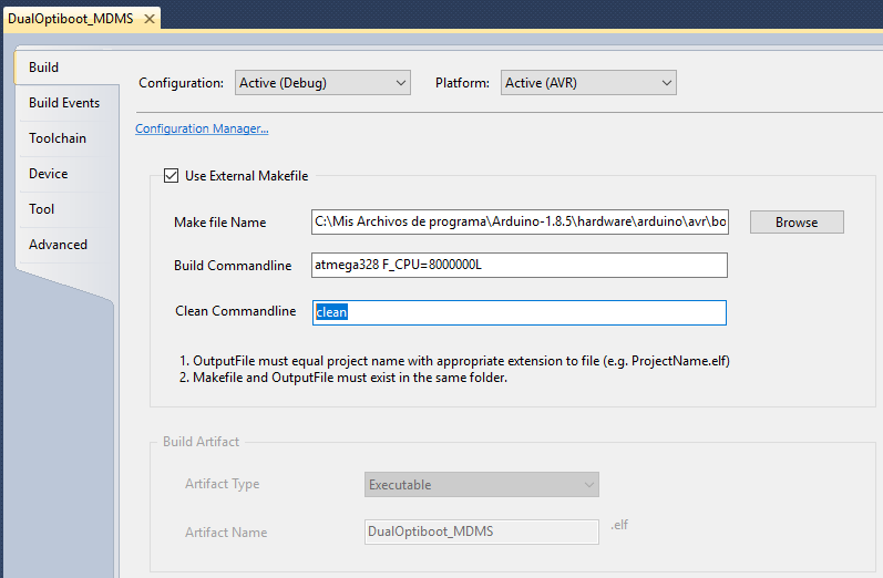
Now in the code of the optiboot.c file you have to modify the Cable Select pin where the flash chip is connected.
In the documentation of Arduino indicate the values of each pin, for pin A0 the codes correspond.
https://www.arduino.cc/en/Reference/PortManipulation/******************* SPI FLASH Code **********************************/ #if defined(__AVR_ATmega168__) || defined(__AVR_ATmega328P__) || defined(__AVR_ATmega88) || defined(__AVR_ATmega8__) || defined(__AVR_ATmega88__) #define FLASHSS_DDR DDRC // <<= Value 1: "Memory address where the pin block is located" #define FLASHSS_PORT PORTC // <<= Value 2: "Block of pins" #define FLASHSS PINC0 // <<= Value 3: "Pin 0 of the indicated pin block (For A0)" #define SS PINB2 #elif defined (__AVR_ATmega1284P__) || defined (__AVR_ATmega644P__) #define FLASHSS_DDR DDRC #define FLASHSS_PORT PORTC #define FLASHSS PINC7 #define SS PINB4 #endif//SPI INIT #if defined(__AVR_ATmega168__) || defined(__AVR_ATmega328P__) || defined(__AVR_ATmega88) || defined(__AVR_ATmega8__) || defined(__AVR_ATmega88__) DDRB |= _BV(SS) | _BV(PB3) | _BV(PB5); DDRC |= _BV(FLASHSS); //OUTPUT for FLASH_SS // <<= Value 4:Inicialización del pin SS FLASH_UNSELECT; PORTB |= _BV(SS); #elif defined (__AVR_ATmega1284P__) || defined (__AVR_ATmega644P__) DDRC |= _BV(FLASHSS); //OUTPUT for FLASH_SS DDRB |= _BV(SS) | _BV(PB5) | _BV(PB7); FLASH_UNSELECT; PORTB |= _BV(SS); #endifFinally, we will only need to execute the code, with the green button in the form of a triangle / play, or with the F5 key) and in the project directory the new bootloader file will be created.
-
I have modified the code to send the temperature every minute, when both relays are off the temperature of the feed funete is 35ºC, when the relays are active is 55ºC. (On the test board, it is not embedded in the wall)
https://giltesa.com/wp-content/uploads/2018/01/Touch-Switch-Temp.txt
-
Hello! Realy good job!
Dimmer good idea too. :+1:
Did you plan to do livolo two gang ? and roller shutter witch current detection?Hello @tet
This circuit does not allow to regulate the light of the lamps, the circuit that will allow it is this other (only changes the red PCB):
https://forum.mysensors.org/topic/8952/wireless-touch-switch-triac-model-for-livolo-crystalsHowever, as it puts in that thread, I am having problems with the regulation of brightness, today I have arrived a new Philips bulb and it works much better than the Ikea bulb however it keeps blinking, I am going to buy some new triacs and optocouplers to see if those work better.
As for your questions, I had not planned to make a switch with two tactile pushbuttons, I think it is uncomfortable to press when there is more than one pushbutton since you have to be aware of which area of the crystal you press, however now you can press with the palm hand in any area to have a single button. In any case, doing that is not complicated and since I am going to share all the files, anyone can customize the plate to their liking.
Does current detection have utility? Is it to know the consumption of the lamp? If it is for that I do not think it is useful to measure the consumption of the lamps independently, I had thought to make a current measurement node that was installed in the electrical panel and there measure the areas that interested me, for example the kitchen.
Kind regards.
-
I would like to know if you plan to do a roller shutter node (for up and down store)?
current detection is to mesure the time to up or down the store. And calculate position in %.
2 gang one for up and the other for down :relaxed:@tet said in 💬 Wireless Touch Switch: Relay Model - (For Livolo crystals):
I would like to know if you plan to do a roller shutter node (for up and down store)?
current detection is to mesure the time to up or down the store. And calculate position in %.
2 gang one for up and the other for downMy idea is to design all the nodes that I need, for now I am developing these four:
Touch push button, relay type
Touch push button, triac type
Multi purpose sensor: Doors, windows, temperature, humidity, light, and three expansion connectors.
Remote controlWhen I finish them I also want to make:
LED strip controller WRGB 12V
Clamp sensor SCT-013 for electrical panel.
PIR sensor
Plug with relay
Roller shutter
Boiler control (or maybe buy it if it is compatible with the control software)As you see my intention is to also design the node to control the blinds, I think the easiest thing would be to manufacture a PCB that is installed inside the double switch of the blind and activate the pulsations. I have not yet documented on how it works but I think that something like that should give good results, all the work would be done by the roller blind electronica, the node would only activate the button (with transistor/ssr).
I must also say that now I do not have a house where to install all these nodes so I am testing them in my test panel but not in a real environment...
-
I just ordered to manufacture the next version of the PCB, actually I also sent to manufacture the other 4 modules.
When the PCBs arrive and perform the necessary tests, I will publish the updated files.On the work panel and openhardware.io there are images of all the modules / nodes.


Hello! It looks like you're interested in this conversation, but you don't have an account yet.
Getting fed up of having to scroll through the same posts each visit? When you register for an account, you'll always come back to exactly where you were before, and choose to be notified of new replies (either via email, or push notification). You'll also be able to save bookmarks and upvote posts to show your appreciation to other community members.
With your input, this post could be even better 💗
Register Login