nRF24Doctor

-
My post was hitting the constraints of the Forum, so I had to cut it up into pieces...
PART2: The sketch for the nRF24DoctorNode:
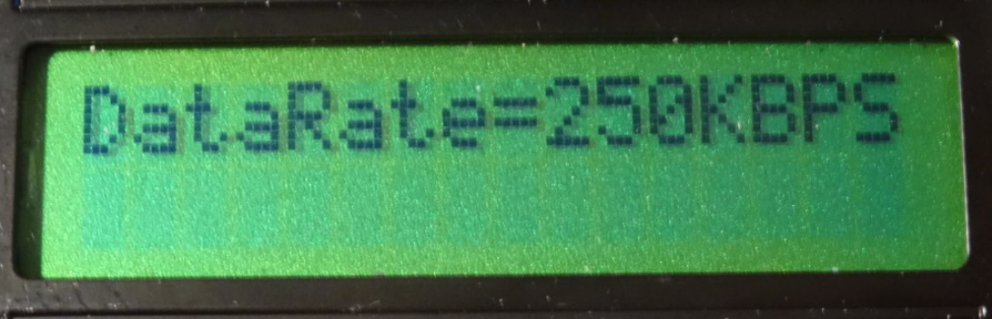
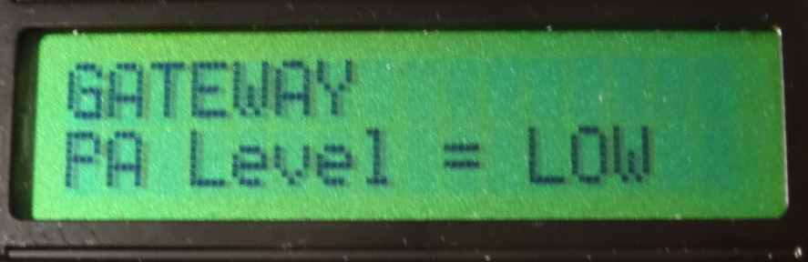
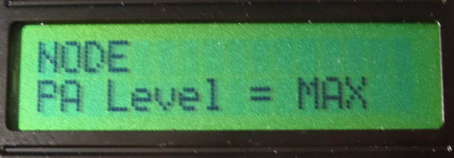
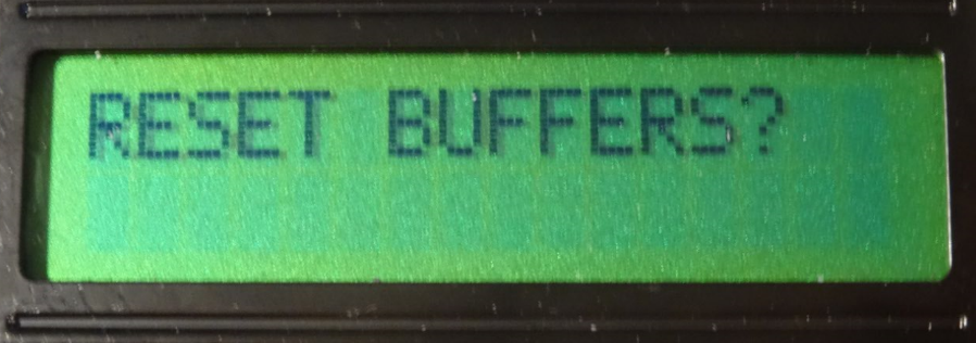
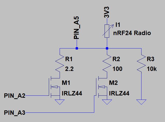
/* PROJECT: MySensors nRF24 Doctor PROGRAMMER: Technovation (based on the work of AWI and Heizelmann) DATE: 2018March27 FILE: nRF24DoctorNode.ino Hardware: ATMega328p board MySensorsAPI: 2.2.0 Summary: a portable nRF24 Radio Doctor to diagnose module performance Change log: 2018/03/27 New Release, based on: https://forum.mysensors.org/topic/3984/nrf24l01-connection-quality-meter */ //**** CONNECTIONS ***** #define BUTTON1_PIN A0 #define BUTTON2_PIN A1 #define MOSFET_2P2OHM_PIN A2 #define MOSFET_100OHM_PIN A3 #define CURRENT_PIN A5 //**** DEBUG ***** #define LOCAL_DEBUG #ifdef LOCAL_DEBUG #define Sprint(a) (Serial.print(a)) // macro as substitute for print, enable if no print wanted #define Sprintln(a) (Serial.println(a)) #else // macro for "no" debug print #define Sprint(a) #define Sprintln(a) #endif //**** MySensors ***** //#define MY_DEBUG // Enable debug prints to serial monitor #define MY_TRANSPORT_WAIT_READY_MS 10 // [ms] Init timeout for gateway not reachable #define MY_NODE_ID 250 // Set a high node ID, which typically will not yet be used in the network #define MY_PARENT_NODE_IS_STATIC // Fixed parent Node ID, else MySensors Transport will attempt automatic fix after successive failures...but we don't want that while diagnosing our connection #define MY_PARENT_NODE_ID 0 // Typically 0 for Gateway #define DESTINATION_NODE 0 // Default 0 = gateway, Settable in Menu #define MY_BAUD_RATE 115200 //**** MySensors - Radio ***** #define MY_RADIO_NRF24 // Enable and select radio type attached #include <SPI.h> #include <MySensors.h> //#include <LiquidCrystal_I2C.h> // LCD display with I2C interface #include <LiquidCrystal.h> // LCD display with parallel interface #include <OneButton.h> //from https://github.com/mathertel/OneButton/blob/master/examples/TwoButtons/TwoButtons.ino //**** LCD ***** #define LCD_COLS 16 #define LCD_ROWS 2 //LiquidCrystal_I2C lcd(0x27, 2, 1, 0, 4, 5, 6, 7, 3, POSITIVE); // Set the LCD I2C address //LiquidCrystal_I2C lcd(0x27, 16, 2); // Set the LCD I2C address LiquidCrystal lcd(8, 7, 6, 5, 4, 3); // LCD with parallel interface //**** BUTTONS ***** OneButton button1(BUTTON1_PIN, true); //PullUp, Activelow OneButton button2(BUTTON2_PIN, true); //PullUp, Activelow //**** EEPROM STORAGE LOCATIONS ***** #define EEPROM_FLAG 0 #define EEPROM_CHANNEL 1 #define EEPROM_PA_LEVEL 2 #define EEPROM_PA_LEVEL_GW 3 #define EEPROM_DATARATE 4 #define EEPROM_BASE_RADIO_ID 5 #define EEPROM_DESTINATION_NODE 6 #define EEPROM_SEND_REPEATS 7 //**** MySensors Messages **** #define CHILD_ID_COUNTER 0 #define CHILD_ID_UPDATE_GATEWAY 0 MyMessage MsgCounter(CHILD_ID_COUNTER, V_CUSTOM); //Send Message Counter value MyMessage MsgUpdateGateway(CHILD_ID_UPDATE_GATEWAY, V_CUSTOM); //Send value for Gateway settings: xxxyz (xxx = Channel, y = PaLevel, z = DataRate) #define DELAY_BETWEEN_MESSAGES_MICROS 500000 //Normal Interval between messages //**** Monitoring Constants&Variables **** const int iMaxNumberOfMessages = 100 ; // Number of Messages Used for MA calculation boolean bArrayFailedMessages[iMaxNumberOfMessages] = { 0 }; // Array for moving average storage boolean bArrayNAckMessages[iMaxNumberOfMessages] = { 0 }; // Array for moving average storage uint16_t iNrFailedMessages = 0; // total of Failed Messages uint16_t iNrNAckMessages = 0; // total of Not Acknowledged Messages uint16_t iMessageCounter = 0; //**** LCD MENU Constants&Variables **** enum mode {STATE_RUN, STATE_RUN2, STATE_RUN3, STATE_CURLEVEL, STATE_SET_RESET, STATE_SET_DESTINATION_NODE, STATE_SET_CHANNEL, STATE_SET_BASE_RADIO_ID, STATE_SET_PALEVEL, STATE_SET_PALEVEL_GW, STATE_SET_DATARATE, STATE_ASK_GATEWAY, STATE_UPDATE_GATEWAY }; mode opState = STATE_RUN; // Default Mode boolean bDspRefresh = true; //nRF24 Settings const uint8_t iNrPaLevels = 4; const char *pcPaLevelNames[iNrPaLevels] = { "MIN", "LOW", "HIGH", "MAX" }; const uint8_t iNrDataRates = 3; const char *pcDataRateNames[iNrDataRates] = { "1MBPS", "2MBPS" , "250KBPS"}; //Define your available RF24_BASE_ID const uint8_t iNrBaseRadioIds = 4; uint8_t RF24_BASE_ID_VAR[MY_RF24_ADDR_WIDTH] = { 0x00,0xFC,0xE1,0xA8,0xA8 }; //Used to Store the active BASE_ID const uint8_t RF24_BASE_ID_VAR1[MY_RF24_ADDR_WIDTH] = { 0x00,0xFC,0xE1,0xA8,0xA8 }; const uint8_t RF24_BASE_ID_VAR2[MY_RF24_ADDR_WIDTH] = { 0x00,0xA1,0xF3,0x09,0xB6 }; const uint8_t RF24_BASE_ID_VAR3[MY_RF24_ADDR_WIDTH] = { 0x00,0xAA,0xA5,0xC4,0xD9 }; const uint8_t RF24_BASE_ID_VAR4[MY_RF24_ADDR_WIDTH] = { 0x00,0xB1,0x47,0xEE,0x82 }; //Load Default Radio values uint8_t iRf24Channel = MY_RF24_CHANNEL; uint8_t iRf24PaLevel = MY_RF24_PA_LEVEL; //PA Level for the Node uint8_t iRf24PaLevelGw = MY_RF24_PA_LEVEL; //PA Level for the Gateway uint8_t iRf24DataRate = MY_RF24_DATARATE; uint8_t iRf24BaseRadioId = 1; uint8_t iDestinationNode = DESTINATION_NODE; //**** Timing **** const uint8_t iNrTimeDelays = 10; uint16_t iMessageIndexBuffer[iNrTimeDelays]={0}; unsigned long lTimeOfTransmit_us[iNrTimeDelays]={0}; unsigned long lTimeDelayBuffer_Destination_us[iNrTimeDelays]={0}; unsigned long lTimeDelayBuffer_FirstHop_us[iNrTimeDelays]={0}; uint16_t iMeanDelayFirstHop_ms = 0; uint16_t iMaxDelayFirstHop_ms = 0; uint16_t iMeanDelayDestination_ms = 0; uint16_t iMaxDelayDestination_ms = 0; //**** Current Measurement **** const uint8_t iNrCurrentMeasurements = 10; //Nr of measurements for averaging uint8_t iPowerMode = 0; const uint8_t iNrPowerModes = 2; const char *pcPowerModeNames[iNrPowerModes] = { "SLEEP", "STANDBY" }; const float uAperBit1 = 488.2813; //uAperBit = ((Vref/1024)/R1)*1e6 = ((1.1/1024)/2.2)*1e6 const float uAperBit2 = 10.74219; //uAperBit = ((Vref/1024)/R2)*1e6 = ((1.1/1024)/100)*1e6 const float uAperBit3 = 0.107422; //uAperBit = ((Vref/1024)/R3)*1e6 = ((1.1/1024)/10000)*1e6 float SleepCurrent_uA = 0; float StandbyCurrent_uA = 0; //**** Remote Gateway Update **** uint8_t iRetryGateway = 0; bool bUpdateGateway = 0; bool bAckGatewayUpdate = 0; const uint8_t iNrGatwayRetryOptions = 3; const char *pcGatewayRetryNames[iNrGatwayRetryOptions] = { "SKIP GATEWAY", "RETRY GATEWAY" , "CANCEL ALL"}; /*****************************************************************************/ /************************************ STARTUP ********************************/ /*****************************************************************************/ void before() { //Initialization before the MySensors library starts up pinMode(CURRENT_PIN, INPUT); //Analog Input for Current Usage Pin pinMode(MOSFET_2P2OHM_PIN,OUTPUT); pinMode(MOSFET_100OHM_PIN,OUTPUT); digitalWrite(MOSFET_2P2OHM_PIN,HIGH); analogReference(INTERNAL); //**** LCD ***** // Wire.begin(); // I2C lcd.begin(LCD_COLS, LCD_ROWS); //lcd.setBacklight(HIGH); //**** BUTTON STATES ***** button1.attachClick(onButton1Pressed); button1.attachLongPressStart(onButton1LongPressed); button2.attachClick(onButton2Pressed); button2.attachDuringLongPress(onButton2Hold); //**** RELOAD SETTINGS FROM EEPROM ***** if (loadState(EEPROM_FLAG) == 0xFF) { //RELOAD SETTINGS LoadStatesFromEEPROM(); switch (iRf24BaseRadioId) { case 1: memcpy(RF24_BASE_ID_VAR,RF24_BASE_ID_VAR1,sizeof(RF24_BASE_ID_VAR)); break; case 2: memcpy(RF24_BASE_ID_VAR,RF24_BASE_ID_VAR2,sizeof(RF24_BASE_ID_VAR)); break; case 3: memcpy(RF24_BASE_ID_VAR,RF24_BASE_ID_VAR3,sizeof(RF24_BASE_ID_VAR)); break; case 4: memcpy(RF24_BASE_ID_VAR,RF24_BASE_ID_VAR4,sizeof(RF24_BASE_ID_VAR)); break; } } else { //LOAD DEFAULT IN CASE OF CLEAN EEPROM saveState(EEPROM_FLAG, 0xFF); SaveStatesToEEPROM(); } } void setup() { loadNewRadioSettings(); //Load the Radio Settings as they are stored in EEPROM } void presentation() { sendSketchInfo("nRF24_Doctor_N250", "1.0"); present(CHILD_ID_COUNTER, S_CUSTOM) ; // "CUSTOM" counter } /*****************************************************************************/ /*********************************** MAIN LOOP *******************************/ /*****************************************************************************/ void loop() { /************ Update Button State ************/ ButtonTick(); /************ Update LCD ************/ if (bDspRefresh) LCD_local_display(); /************ PROCESS DIFFERENT OPERATIONAL STATES ************/ // RUN, RUN2,RUN3: Are all similar with respect to processing, but show different results on the LCD static unsigned long lLastTransmit = 0; switch (opState) { case STATE_RUN: case STATE_RUN2: case STATE_RUN3:{ // Transmit Message transmit(); lLastTransmit = micros(); getMeanAndMaxFromArray(&iMeanDelayFirstHop_ms,&iMaxDelayFirstHop_ms,lTimeDelayBuffer_FirstHop_us,iNrTimeDelays); getMeanAndMaxFromArray(&iMeanDelayDestination_ms,&iMaxDelayDestination_ms,lTimeDelayBuffer_Destination_us,iNrTimeDelays); bDspRefresh = true; break; } case STATE_CURLEVEL:{ //First round: Measure 10x Current in "Standby Mode", then do the same for "Sleep mode" iPowerMode = !iPowerMode; //Toggle between modes: "Standby" & "Sleep" if (iPowerMode == 1){ //Mode: Standby transmit(); lLastTransmit = micros(); wait(50); StandbyCurrent_uA = uAperBit1*GetAvgADCBits(iNrCurrentMeasurements); } else{ //Mode: Sleep transportDisable(); SleepCurrent_uA = uAperBit1*GetAvgADCBits(iNrCurrentMeasurements); if (SleepCurrent_uA < 10000){ //Set Higher Sensitivity: uAperBit2 digitalWrite(MOSFET_2P2OHM_PIN,LOW); digitalWrite(MOSFET_100OHM_PIN,HIGH); SleepCurrent_uA = uAperBit2*GetAvgADCBits(iNrCurrentMeasurements); } if (SleepCurrent_uA < 100){ //Set Higher Sensitivity: uAperBit3 digitalWrite(MOSFET_2P2OHM_PIN,LOW); digitalWrite(MOSFET_100OHM_PIN,LOW); SleepCurrent_uA = uAperBit3*GetAvgADCBits(iNrCurrentMeasurements); } //Restore standby power state digitalWrite(MOSFET_2P2OHM_PIN,HIGH); //Enable 2.2Ohm digitalWrite(MOSFET_100OHM_PIN,LOW); transportStandBy();transmit();lLastTransmit = micros(); } bDspRefresh = true; break; } default:{ lLastTransmit = micros()-DELAY_BETWEEN_MESSAGES_MICROS; wait(25); // To limit LCD update rate break; } } //Wait before sending next message while ((micros()- lLastTransmit) < DELAY_BETWEEN_MESSAGES_MICROS){// wait for things to settle and ack's to arrive wait(1); ButtonTick(); //Check for button changes....we must keep responsive } } /*****************************************************************************/ /************************ RECEIVE & TRANSMIT FUNCTIONS ***********************/ /*****************************************************************************/ void receive(const MyMessage &message) { if (message.isAck() == 1 && message.type == V_CUSTOM && message.sensor==CHILD_ID_COUNTER){ //Acknowledge message & of correct type uint16_t iNewMessage = message.getUInt(); // get received value uint16_t iIndexInArray = iNewMessage % iMaxNumberOfMessages; bArrayNAckMessages[iIndexInArray] = 0; // set corresponding flag to received. //Check Message (Round trip) Delay uint8_t iIndexInTimeArray = IndexOfValueInArray(iNewMessage, iMessageIndexBuffer, iNrTimeDelays); //Look-up if message is present in MessageIndexBuffer for delay calculation if ((iIndexInTimeArray >=0) && iIndexInTimeArray <=iNrTimeDelays){ lTimeDelayBuffer_Destination_us[iIndexInTimeArray] = micros()-lTimeOfTransmit_us[iIndexInTimeArray]; } iNrNAckMessages--; //Received an Acknowledge Message (so one less No Ack) } //Gateway Update Acknowledge - if we have received this we can "safely" apply the new settings to this node if (message.isAck() == 1 && message.type == V_CUSTOM && message.sensor==CHILD_ID_UPDATE_GATEWAY){ //Acknowledge message & of correct type & Sensor bAckGatewayUpdate = 1; } } void transmit() { static int iIndexInArrayFailedMessages = 0 ; static int iIndexInArrayTimeMessages = 0 ; iMessageCounter++; //Cyclic Index counters of arrays iIndexInArrayFailedMessages = iMessageCounter % iMaxNumberOfMessages; iIndexInArrayTimeMessages = iMessageCounter % iNrTimeDelays; bArrayNAckMessages[iIndexInArrayFailedMessages] = 1; // set corresponding flag to "Not Received Yet" //Prepare time stamp logging for transmit lTimeDelayBuffer_Destination_us[iIndexInArrayTimeMessages] = 0; // Clear Buffer value, new value will be written when message is received iMessageIndexBuffer[iIndexInArrayTimeMessages]=iMessageCounter; // To link the Time Stamp to the correct message when we receive the acknowledge iNrNAckMessages++; // Add one to the Not Acknowledged Message counter and remove it again if/when it is received. lTimeOfTransmit_us[iIndexInArrayTimeMessages] = micros(); //Transmit message with software ack request (returned in "receive function"), the boolean returned here is a Hardware hop-to-hop Ack boolean success = send(MsgCounter.setDestination(iDestinationNode).set(iMessageCounter), true); if (!success) { lTimeDelayBuffer_FirstHop_us[iIndexInArrayTimeMessages] = 0; //It failed, so I can't use it to determine a First Hop Delay (i.e. it is "infinite" delay as it failed) bArrayFailedMessages[iIndexInArrayFailedMessages] = true; //Log it as a failed message (for rolling average) iNrFailedMessages++ ; } else{ lTimeDelayBuffer_FirstHop_us[iIndexInArrayTimeMessages] = micros() - lTimeOfTransmit_us[iIndexInArrayTimeMessages]; //Log First Hop Delay in buffer bArrayFailedMessages[iIndexInArrayFailedMessages] = false; //Log it as a not-failed = succesful message (for rolling average) } } /********************************************************************************/ /************************ CONFIGURE nRF24 RADIO FUNCTIONS ***********************/ /********************************************************************************/ void loadNewRadioSettings() { ClearStorageAndCounters(); uint8_t iTempVar0 = RF24_BASE_ID_VAR[0]; uint8_t rfsetup = ( ((iRf24DataRate & 0b10 ) << 4) | ((iRf24DataRate & 0b01 ) << 3) | (iRf24PaLevel << 1) ) + 1; //!< RF24_RF_SETUP, +1 for Si24R1 and LNA RF24_setChannel(iRf24Channel); RF24_setRFSetup(rfsetup); RF24_enableFeatures(); RF24_BASE_ID_VAR[0] = RF24_BROADCAST_ADDRESS; RF24_setPipeAddress(RF24_REG_RX_ADDR_P0 + RF24_BROADCAST_PIPE, (uint8_t*)&RF24_BASE_ID_VAR, RF24_BROADCAST_PIPE > 1 ? 1 : MY_RF24_ADDR_WIDTH); RF24_setPipeAddress(RF24_REG_RX_ADDR_P0, (uint8_t*)&RF24_BASE_ID_VAR, MY_RF24_ADDR_WIDTH); RF24_setPipeAddress(RF24_REG_TX_ADDR, (uint8_t*)&RF24_BASE_ID_VAR, MY_RF24_ADDR_WIDTH); RF24_BASE_ID_VAR[0] = iTempVar0; //lcd.home(); lcd.setCursor(0, 0); lcd.print("nRF24 DOCTOR"); lcd.setCursor(0, 1); lcd.print("Connecting..."); transportWaitUntilReady(10000); // Give it 10[s] to connect, else continue to allow user to set new connection settings } void loadNewRadioSettingsGateway() { switch (iRetryGateway){ case 0: //Skip Gateway update (= only update this Node) //Store new values to EEPROM & Restart the program SaveStatesToEEPROM(); asm volatile (" jmp 0"); //Do a Soft Reset - This allows for the radio to correctly reload with the new settings from EEPROM break; case 1: { //(Re-)try Gateway update uint16_t iMessageToGateway = iRf24Channel*100+iRf24PaLevelGw*10+iRf24DataRate; boolean success = send(MsgUpdateGateway.setDestination(0).setSensor(250).set(iMessageToGateway), true); //Transmit message with software ack request (returned in "receive function") int nRepeats = 0; while (!success && nRepeats<10) { //Re-try nRepeats++; success = send(MsgUpdateGateway.setDestination(0).set(iMessageToGateway), true); } wait(2000); //wait for ACK from Gateway if (bAckGatewayUpdate){ //Store new values to EEPROM & Restart the program SaveStatesToEEPROM(); asm volatile (" jmp 0"); //Do a Soft Reset - This allows for the radio to correctly reload with the new settings from EEPROM } break; } case 2: //Cancel All opState = STATE_RUN; LoadStatesFromEEPROM(); bDspRefresh = true; break; } } /*****************************************************************/ /************************ EEPROM FUNCTIONS ***********************/ /*****************************************************************/ void LoadStatesFromEEPROM() { iRf24Channel = loadState(EEPROM_CHANNEL); iRf24PaLevel = loadState(EEPROM_PA_LEVEL); iRf24PaLevelGw = loadState(EEPROM_PA_LEVEL_GW); iRf24DataRate = loadState(EEPROM_DATARATE); iRf24BaseRadioId = loadState(EEPROM_BASE_RADIO_ID); iDestinationNode = loadState(EEPROM_DESTINATION_NODE); } void SaveStatesToEEPROM() { saveState(EEPROM_CHANNEL, iRf24Channel); saveState(EEPROM_PA_LEVEL, iRf24PaLevel); saveState(EEPROM_PA_LEVEL_GW, iRf24PaLevelGw); saveState(EEPROM_DATARATE, iRf24DataRate); saveState(EEPROM_BASE_RADIO_ID, iRf24BaseRadioId); saveState(EEPROM_DESTINATION_NODE, iDestinationNode); } /*****************************************************************/ /************************ BUTTON FUNCTIONS ***********************/ /*****************************************************************/ void ButtonTick() { //Check Button States (should be done Frequently button1.tick(); button2.tick(); } void onButton1Pressed() { //Scroll through the menu items lcd.clear(); bDspRefresh = true; switch (opState) { case STATE_RUN: opState = STATE_RUN2; break; case STATE_RUN2: opState = STATE_RUN3; break; case STATE_RUN3: opState = STATE_CURLEVEL; break; case STATE_CURLEVEL: opState = STATE_SET_RESET; break; case STATE_SET_RESET: opState = STATE_SET_DESTINATION_NODE; break; case STATE_SET_DESTINATION_NODE: opState = STATE_SET_CHANNEL; break; case STATE_SET_CHANNEL: opState = STATE_SET_PALEVEL; break; case STATE_SET_PALEVEL: opState = STATE_SET_PALEVEL_GW; break; case STATE_SET_PALEVEL_GW: opState = STATE_SET_DATARATE; break; case STATE_SET_DATARATE: opState = STATE_SET_BASE_RADIO_ID; break; case STATE_SET_BASE_RADIO_ID: opState = STATE_ASK_GATEWAY; break; case STATE_ASK_GATEWAY: opState = STATE_UPDATE_GATEWAY; loadNewRadioSettingsGateway(); break; case STATE_UPDATE_GATEWAY: loadNewRadioSettingsGateway(); break; } } void onButton2Pressed() { //Apply/Select change (if available). In Viewing windows: toggle (reversed) bDspRefresh = true; switch (opState) { case STATE_RUN: //Do nothing break; case STATE_RUN2: //Do nothing break; case STATE_RUN3: //Do nothing break; case STATE_CURLEVEL: //Do nothing break; case STATE_SET_RESET: ClearStorageAndCounters(); opState = STATE_RUN; break; //Select Radio changes: case STATE_SET_DESTINATION_NODE: iDestinationNode++; break; case STATE_SET_CHANNEL: iRf24Channel++; if (iRf24Channel > 125) iRf24Channel = 0; break; case STATE_SET_PALEVEL: iRf24PaLevel++; if (iRf24PaLevel > (iNrPaLevels-1)) iRf24PaLevel = 0; break; case STATE_SET_PALEVEL_GW: iRf24PaLevelGw++; if (iRf24PaLevelGw > (iNrPaLevels-1)) iRf24PaLevelGw = 0; break; case STATE_SET_DATARATE: iRf24DataRate++; if (iRf24DataRate > (iNrDataRates-1)) iRf24DataRate = 0; break; case STATE_SET_BASE_RADIO_ID: iRf24BaseRadioId++; if (iRf24BaseRadioId > iNrBaseRadioIds) iRf24BaseRadioId = 1; switch (iRf24BaseRadioId) { case 1: memcpy(RF24_BASE_ID_VAR,RF24_BASE_ID_VAR1,sizeof(RF24_BASE_ID_VAR)); break; case 2: memcpy(RF24_BASE_ID_VAR,RF24_BASE_ID_VAR2,sizeof(RF24_BASE_ID_VAR)); break; case 3: memcpy(RF24_BASE_ID_VAR,RF24_BASE_ID_VAR3,sizeof(RF24_BASE_ID_VAR)); break; case 4: memcpy(RF24_BASE_ID_VAR,RF24_BASE_ID_VAR4,sizeof(RF24_BASE_ID_VAR)); break; } break; case STATE_ASK_GATEWAY: bUpdateGateway= !bUpdateGateway; if (bUpdateGateway){ iRetryGateway = 1; } else{ iRetryGateway = 0; } break; case STATE_UPDATE_GATEWAY: iRetryGateway++; if (iRetryGateway > (iNrGatwayRetryOptions-1)) iRetryGateway = 0; /* switch(iRetryGateway){ case 0: bUpdateGateway = 0; break; case 1: bUpdateGateway = 1; break; case 2: bUpdateGateway = 0; break; } */ break; } } void onButton1LongPressed() { // Return to normal RUN state without changing any settings (recall last set from EEPROM) opState = STATE_RUN; LoadStatesFromEEPROM(); bDspRefresh = true; } void onButton2Hold() { //Scroll through numbers quickly switch (opState) { case STATE_SET_CHANNEL: iRf24Channel++; if (iRf24Channel > 125) iRf24Channel = 0; bDspRefresh = true; break; case STATE_SET_DESTINATION_NODE: iDestinationNode++; bDspRefresh = true; break; } } /*****************************************************************/ /**************** ARRAY PROCESSING FUNCTIONS *********************/ /*****************************************************************/ uint8_t IndexOfValueInArray(uint16_t val, uint16_t *array, uint8_t size){ // Find the (first) array element which equals val and return the index. // If val not found in the array return 255 for (int i=0; i < size; i++) { if (array[i] == val){ return i; } } return 255; //Not Found } int GetNrOfTrueValuesInArray(boolean countArray[], int size) { // Calculate number of TRUE values in array int Counter = 0 ; for (int i = 0 ; i < size ; i++) {Counter += countArray[i];} return Counter; } void ClearStorageAndCounters() { for (int n = 0; n < iMaxNumberOfMessages; n++){ bArrayFailedMessages[n] = 0; bArrayNAckMessages[n] = 0; } iNrNAckMessages = iMessageCounter = iNrFailedMessages = 0; bAckGatewayUpdate = 0; } void getMeanAndMaxFromArray(uint16_t *mean_value, uint16_t *max_value, unsigned long *buffer, uint8_t size) { //Note: excluding 0 values from mean calculation uint8_t iNrOfSamples=0; //max equals size unsigned long lMaxValue=0; //max Array value float sum=0; for (int i=0; i < size; i++) { if (buffer[i] != 0){ sum = sum + (float)buffer[i]; lMaxValue = max(lMaxValue,buffer[i]); iNrOfSamples++; } } if (iNrOfSamples !=0){ *mean_value = (uint16_t) ((sum / (float)iNrOfSamples)/1000); *max_value = (uint16_t) (lMaxValue/1000L); } else { *mean_value = 65535; //INF identifier *max_value = 65535; //INF identifier } } float GetAvgADCBits(int iNrSamples) { float sum = 0; for (int i=0; i < iNrSamples; i++) { sum = sum + analogRead(CURRENT_PIN); wait(1); // Need some time for the high impedance measurement @ 10kOhm } return ((float)sum/(float)iNrSamples); } /*****************************************************************/ /************************* LCD FUNCTIONS *************************/ /*****************************************************************/ void print_LCD_line(const char *string,int row, int col) { lcd.setCursor(col-1,row-1); lcd.print(string); } void LCD_local_display(void) { static mode prevOpState = STATE_RUN; //Remember previous state to allow for partial LCD updates char buf[LCD_COLS+1]; bDspRefresh = false; switch (opState) { case STATE_RUN: { snprintf(buf, sizeof buf, "P%-3dFAIL%4d%3d%%", MY_PARENT_NODE_ID, iNrFailedMessages, GetNrOfTrueValuesInArray(bArrayFailedMessages, iMaxNumberOfMessages)); print_LCD_line(buf,1, 1); snprintf(buf, sizeof buf, "D%-3dNACK%4d%3d%%", iDestinationNode , iNrNAckMessages, GetNrOfTrueValuesInArray(bArrayNAckMessages, iMaxNumberOfMessages)); print_LCD_line(buf,2, 1); break; } case STATE_RUN2: { if (iMaxDelayFirstHop_ms>9999){ snprintf(buf, sizeof buf, "HOP1 dTmax INF"); } else{ snprintf(buf, sizeof buf, "HOP1 dTmax%4dms",iMaxDelayFirstHop_ms); } print_LCD_line(buf,1, 1); if (iMaxDelayDestination_ms>9999){ snprintf(buf, sizeof buf, "D%-3d dTmax INF",iDestinationNode,iMaxDelayDestination_ms); } else{ snprintf(buf, sizeof buf, "D%-3d dTmax%4dms",iDestinationNode,iMaxDelayDestination_ms); } print_LCD_line(buf,2, 1); break; } case STATE_RUN3: { snprintf(buf, sizeof buf, "MESSAGE COUNT: "); print_LCD_line(buf,1, 1); snprintf(buf, sizeof buf, " %5d",iMessageCounter); print_LCD_line(buf,2, 1); break; } case STATE_CURLEVEL: { float fCurrent_uA = 0; if (iPowerMode == 1){ fCurrent_uA = StandbyCurrent_uA; } else{ fCurrent_uA = SleepCurrent_uA; } Sprint("iPowerMode:");Sprintln(iPowerMode); Sprint("fCurrent_uA:");Sprintln(fCurrent_uA); if (fCurrent_uA > 1000){ int Current_mA = (int)(fCurrent_uA/1000); if (Current_mA>=300){ snprintf(buf, sizeof buf, "%s[mA]= ERR",pcPowerModeNames[iPowerMode],Current_mA); } else if (Current_mA>=100){ snprintf(buf, sizeof buf, "%s[mA]=%4d",pcPowerModeNames[iPowerMode],Current_mA); } else if (Current_mA>=10){ int iDecCurrent = (int)(((fCurrent_uA/1000)-(float)Current_mA)*10+0.5); snprintf(buf, sizeof buf, "%s[mA]=%2d.%1d",pcPowerModeNames[iPowerMode],Current_mA,iDecCurrent); } else { int iDecCurrent = (int)(((fCurrent_uA/1000)-(float)Current_mA)*100+0.5); snprintf(buf, sizeof buf, "%s[mA]=%1d.%2d",pcPowerModeNames[iPowerMode],Current_mA,iDecCurrent); } } else if (fCurrent_uA < 100){ int iCurrent_uA = (int)fCurrent_uA; int iDecCurrent_uA = (int)((fCurrent_uA-(float)iCurrent_uA)*10+0.5); snprintf(buf, sizeof buf, "%s[uA]=%2d.%1d",pcPowerModeNames[iPowerMode],iCurrent_uA,iDecCurrent_uA); } else{ snprintf(buf, sizeof buf, "%s[uA]=%4d",pcPowerModeNames[iPowerMode],(int)fCurrent_uA); } if (iPowerMode == 1){ print_LCD_line(buf,1, 1); } else{ print_LCD_line(buf,2, 1); } break; } case STATE_SET_RESET: { snprintf(buf, sizeof buf, "RESET BUFFERS?"); print_LCD_line(buf,1, 1); break; } case STATE_SET_DESTINATION_NODE: { if(opState==prevOpState){ char buf2[4]; lcd.setCursor(13, 0); snprintf(buf2, sizeof buf2, "%3d", iDestinationNode); lcd.print(buf2); } else{ snprintf(buf, sizeof buf, "DEST. NODE = %3d", iDestinationNode); print_LCD_line(buf,1, 1); } break; } case STATE_SET_CHANNEL: { if(opState==prevOpState){ char buf2[4]; lcd.setCursor(13, 0); snprintf(buf2, sizeof buf2, "%3d", iRf24Channel); lcd.print(buf2); } else{ snprintf(buf, sizeof buf, "CHANNEL NR = %3d", iRf24Channel); print_LCD_line(buf,1, 1); } break; } case STATE_SET_PALEVEL: { lcd.clear(); snprintf(buf, sizeof buf, "NODE"); print_LCD_line(buf,1, 1); snprintf(buf, sizeof buf, "PA Level = %s", pcPaLevelNames[iRf24PaLevel]); print_LCD_line(buf,2, 1); break; } case STATE_SET_PALEVEL_GW: { lcd.clear(); snprintf(buf, sizeof buf, "GATEWAY"); print_LCD_line(buf,1, 1); snprintf(buf, sizeof buf, "PA Level = %s", pcPaLevelNames[iRf24PaLevelGw]); print_LCD_line(buf,2, 1); break; } case STATE_SET_DATARATE: { lcd.clear(); snprintf(buf, sizeof buf, "DataRate=%s", pcDataRateNames[iRf24DataRate]); print_LCD_line(buf,1, 1); break; } case STATE_SET_BASE_RADIO_ID: { lcd.clear(); snprintf(buf, sizeof buf, "Base Radio ID= "); print_LCD_line(buf,1, 1); snprintf(buf, sizeof buf, "%02X:%0.2X:%0.2X:%0.2X:%0.2X",RF24_BASE_ID_VAR[0],RF24_BASE_ID_VAR[1],RF24_BASE_ID_VAR[2],RF24_BASE_ID_VAR[3],RF24_BASE_ID_VAR[4]); print_LCD_line(buf,2, 1); break; } case STATE_ASK_GATEWAY: { lcd.clear(); snprintf(buf, sizeof buf, "UPDATE GATEWAY?:"); print_LCD_line(buf,1, 1); if (bUpdateGateway){ snprintf(buf, sizeof buf, "YES"); print_LCD_line(buf,2, 14); } else{ snprintf(buf, sizeof buf, "NO"); print_LCD_line(buf,2, 15); } break; } case STATE_UPDATE_GATEWAY: { lcd.clear(); snprintf(buf, sizeof buf, "FAILED GATEWAY!"); print_LCD_line(buf,1, 1); snprintf(buf, sizeof buf,"%s",pcGatewayRetryNames[iRetryGateway]); print_LCD_line(buf,2, 1); break; } } prevOpState = opState; }And finally PART3 the sketch for the nRF24DoctorGateway
/**
* The MySensors Arduino library handles the wireless radio link and protocol
* between your home built sensors/actuators and HA controller of choice.
* The sensors forms a self healing radio network with optional repeaters. Each
* repeater and gateway builds a routing tables in EEPROM which keeps track of the
* network topology allowing messages to be routed to nodes.
*
* Created by Henrik Ekblad <henrik.ekblad@mysensors.org>
* Copyright (C) 2013-2015 Sensnology AB
* Full contributor list: https://github.com/mysensors/Arduino/graphs/contributors
*
* Documentation: http://www.mysensors.org
* Support Forum: http://forum.mysensors.org
*
* This program is free software; you can redistribute it and/or
* modify it under the terms of the GNU General Public License
* version 2 as published by the Free Software Foundation.
*
*******************************
*
* DESCRIPTION
* The ArduinoGateway prints data received from sensors on the serial link.
* The gateway accepts input on seral which will be sent out on radio network.
*
* The GW code is designed for Arduino Nano 328p / 16MHz
*
* Wire connections (OPTIONAL):
* - Inclusion button should be connected between digital pin 3 and GND
* - RX/TX/ERR leds need to be connected between +5V (anode) and digital pin 6/5/4 with resistor 270-330R in a series
*
* LEDs (OPTIONAL):
* - To use the feature, uncomment any of the MY_DEFAULT_xx_LED_PINs
* - RX (green) - blink fast on radio message recieved. In inclusion mode will blink fast only on presentation recieved
* - TX (yellow) - blink fast on radio message transmitted. In inclusion mode will blink slowly
* - ERR (red) - fast blink on error during transmission error or recieve crc error
*
*/

//---------------- SET SPECIFIC MY SENSORS SETTINGS ---------------------//

// Enable debug prints to serial monitor
#define MY_DEBUG
#define MY_DEBUG_VERBOSE_SIGNING

// Enable and select radio type attached
#define MY_RADIO_NRF24


//#define MY_RF24_CHANNEL 1
//#define MY_RF24_DATARATE RF24_1MBPS

//If you are using an Arduino Mega
#define MY_RF24_CE_PIN 49
#define MY_RF24_CS_PIN 53
//Enable receiving buffer feature.
//#define MY_RF24_IRQ_PIN 2
//#define MY_RX_MESSAGE_BUFFER_FEATURE

// Set LOW transmit power level as default, if you have an amplified NRF-module and
// power your radio separately with a good regulator you can turn up PA level.
#define MY_RF24_PA_LEVEL RF24_PA_MAX

// Signing settings
//#define MY_SIGNING_SOFT
//#define MY_SIGNING_SOFT_RANDOMSEED_PIN 7
//#define MY_SIGNING_REQUEST_SIGNATURES
//These codes should be programmed in EEPROM through SecurityPersonalizer.ino with USB connection once (will be maintained with reprogramming of new sketches) and preferably not send over the air)
//#define MY_SOFT_HMAC_KEY 0xFC,0x7E,0xA0,0x9F,0xEA,0x20,0x14,0xD0,0xC4,0x5F,0xBB,0xA3,0x70,0xE8,0xA1,0xDD,0x72,0x3E,0xBB,0x19,0x50,0x8E,0x35,0x7D,0x44,0x25,0xBB,0x7A,0xF4,0xAA,0x28,0x76
//#define MY_SOFT_SERIAL 0x2C,0xA0,0x3F,0x21,0x08,0x80,0xF5,0x8A,0xC4
//#define MY_AES_KEY 0x8F,0x87,0x9B,0x25,0xEE,0xAC,0x6A,0x36,0x3D,0xD3,0xF8,0x35,0x5F,0xD5,0xCB,0x96

// RF24 encryption is enabled in MyConfig.h (all nodes and gateway must have this enabled, and all must be personalized with the same AES key)
//#define MY_RF24_ENABLE_ENCRYPTION

// Enable serial gateway
#define MY_GATEWAY_SERIAL
// Define a lower baud rate for Arduino's running on 8 MHz (Arduino Pro Mini 3.3V & SenseBender)
#if F_CPU == 8000000L
#define MY_BAUD_RATE 38400
#endif

// Enable inclusion mode
#define MY_INCLUSION_MODE_FEATURE
// Enable Inclusion mode button on gateway
#define MY_INCLUSION_BUTTON_FEATURE

// Inverses behavior of inclusion button (if using external pullup)
//#define MY_INCLUSION_BUTTON_EXTERNAL_PULLUP

// Set inclusion mode duration (in seconds)
#define MY_INCLUSION_MODE_DURATION 60
// Digital pin used for inclusion mode button
#define MY_INCLUSION_MODE_BUTTON_PIN  3

// Set blinking period
#define MY_DEFAULT_LED_BLINK_PERIOD 300

// Inverses the behavior of leds
//#define MY_WITH_LEDS_BLINKING_INVERSE

// Flash leds on rx/tx/err
// Uncomment to override default HW configurations
#define MY_DEFAULT_ERR_LED_PIN 4  // Error led pin
#define MY_DEFAULT_TX_LED_PIN  5  // the PCB, on board LED
#define MY_DEFAULT_RX_LED_PIN  6  // Receive led pin

//**** MySensors Messages ****
#define MY_TRANSPORT_SANITY_CHECK_INTERVAL_MS 3000000000			//To Prevent the MySensors library from resetting back to default radio settings
#include <MySensors.h>
#define CHILD_ID_UPDATE_GATEWAY 250
MyMessage MsgUpdateGateway(CHILD_ID_UPDATE_GATEWAY, V_CUSTOM);   	//Send value for Gateway settings: xxxyz (xxx = Channel, y = PaLevel, z = DataRate)
uint8_t iRf24Channel 		= MY_RF24_CHANNEL;
uint8_t iRf24PaLevelGw 		= MY_RF24_PA_LEVEL;
uint8_t iRf24DataRate 		= MY_RF24_DATARATE;
bool bLoadNewRadioSettings 	= 0;
const uint8_t iNrPaLevels = 4;
const char *pcPaLevelNames[iNrPaLevels] 		= { "MIN", "LOW", "HIGH", "MAX" };
const uint8_t iNrDataRates = 3;
const char *pcDataRateNames[iNrDataRates] 		= { "1MBPS", "2MBPS" , "250KBPS"};
#define DELAY_BETWEEN_RADIO_SETTINGS_PRINT 20000	//Print Radio Settings to Serial Monitor every x[ms]

//**** DEBUG *****
#define LOCAL_DEBUG

#ifdef LOCAL_DEBUG
#define Sprint(a) (Serial.print(a))           	// macro as substitute for print, enable if no print wanted
#define Sprintln(a) (Serial.println(a))
#else											// macro for "no" debug print
#define Sprint(a)
#define Sprintln(a)
#endif


//-----------------------------------------------------------------------//


void setup()
{
	//loadNewRadioSettings();	//Load the Radio Settings as transmitted by the nRF24 Doctor Node
}

void presentation()
{
	// Present locally attached sensors
}

void loop()
{
	static unsigned long lLastRadioSettingsPrint = millis();
	wait(1);
	//Set new Radio settings by nRF24 Doctor Node
	if (bLoadNewRadioSettings){
		bLoadNewRadioSettings = 0;
		loadNewRadioSettings();
	}
	//Regularly print the Radio Settings we are using
	if ((millis()- lLastRadioSettingsPrint) > DELAY_BETWEEN_RADIO_SETTINGS_PRINT){// wait for things to settle and ack's to arrive
		lLastRadioSettingsPrint = millis();
		PrintRadioSettings();
	}
}

/*****************************************************************************/
/************************ RECEIVE & TRANSMIT FUNCTIONS ***********************/
/*****************************************************************************/
void receive(const MyMessage &message) {
	if (message.type == V_CUSTOM && message.sensor==CHILD_ID_UPDATE_GATEWAY){	//Acknowledge message & of correct type & Sensor
		uint16_t iNewMessage = message.getUInt();           // get received value
		//Extract the new Gateway settings
		iRf24Channel 	= (uint16_t)(iNewMessage/100U);
		iRf24PaLevelGw 	= (uint16_t)((iNewMessage/10U)%10);
		iRf24DataRate 	= (uint16_t)(iNewMessage%10);
		bLoadNewRadioSettings = 1;
		Sprintln("Received new Radio settings.");
	}
}

/********************************************************************************/
/************************ CONFIGURE nRF24 RADIO FUNCTIONS ***********************/
/********************************************************************************/
void loadNewRadioSettings() {
	uint8_t rfsetup = ( ((iRf24DataRate & 0b10 ) << 4) | ((iRf24DataRate & 0b01 ) << 3) | (iRf24PaLevelGw << 1) ) + 1;		//!< RF24_RF_SETUP, +1 for Si24R1 and LNA
	RF24_setChannel(iRf24Channel);
	RF24_setRFSetup(rfsetup);
	RF24_enableFeatures();
	Sprint("Updated Radio Settings!\t");
	PrintRadioSettings();
}

/********************************************************************************/
/******************************** SERIAL OUTPUT *********************************/
/********************************************************************************/
void PrintRadioSettings() {
	Sprint("Channel:");Sprint(iRf24Channel);Sprint("\t");
	Sprint("PaLevel:");Sprint(pcPaLevelNames[iRf24PaLevelGw]);Sprint("\t");
	Sprint("DataRate:");Sprint(pcDataRateNames[iRf24DataRate]);Sprintln("\t");
}
I hope this will be helpful to others to diagnose and doctor their nRF24 Connections.
-
And finally PART3 the sketch for the nRF24DoctorGateway
/**
* The MySensors Arduino library handles the wireless radio link and protocol
* between your home built sensors/actuators and HA controller of choice.
* The sensors forms a self healing radio network with optional repeaters. Each
* repeater and gateway builds a routing tables in EEPROM which keeps track of the
* network topology allowing messages to be routed to nodes.
*
* Created by Henrik Ekblad <henrik.ekblad@mysensors.org>
* Copyright (C) 2013-2015 Sensnology AB
* Full contributor list: https://github.com/mysensors/Arduino/graphs/contributors
*
* Documentation: http://www.mysensors.org
* Support Forum: http://forum.mysensors.org
*
* This program is free software; you can redistribute it and/or
* modify it under the terms of the GNU General Public License
* version 2 as published by the Free Software Foundation.
*
*******************************
*
* DESCRIPTION
* The ArduinoGateway prints data received from sensors on the serial link.
* The gateway accepts input on seral which will be sent out on radio network.
*
* The GW code is designed for Arduino Nano 328p / 16MHz
*
* Wire connections (OPTIONAL):
* - Inclusion button should be connected between digital pin 3 and GND
* - RX/TX/ERR leds need to be connected between +5V (anode) and digital pin 6/5/4 with resistor 270-330R in a series
*
* LEDs (OPTIONAL):
* - To use the feature, uncomment any of the MY_DEFAULT_xx_LED_PINs
* - RX (green) - blink fast on radio message recieved. In inclusion mode will blink fast only on presentation recieved
* - TX (yellow) - blink fast on radio message transmitted. In inclusion mode will blink slowly
* - ERR (red) - fast blink on error during transmission error or recieve crc error
*
*/

//---------------- SET SPECIFIC MY SENSORS SETTINGS ---------------------//

// Enable debug prints to serial monitor
#define MY_DEBUG
#define MY_DEBUG_VERBOSE_SIGNING

// Enable and select radio type attached
#define MY_RADIO_NRF24


//#define MY_RF24_CHANNEL 1
//#define MY_RF24_DATARATE RF24_1MBPS

//If you are using an Arduino Mega
#define MY_RF24_CE_PIN 49
#define MY_RF24_CS_PIN 53
//Enable receiving buffer feature.
//#define MY_RF24_IRQ_PIN 2
//#define MY_RX_MESSAGE_BUFFER_FEATURE

// Set LOW transmit power level as default, if you have an amplified NRF-module and
// power your radio separately with a good regulator you can turn up PA level.
#define MY_RF24_PA_LEVEL RF24_PA_MAX

// Signing settings
//#define MY_SIGNING_SOFT
//#define MY_SIGNING_SOFT_RANDOMSEED_PIN 7
//#define MY_SIGNING_REQUEST_SIGNATURES
//These codes should be programmed in EEPROM through SecurityPersonalizer.ino with USB connection once (will be maintained with reprogramming of new sketches) and preferably not send over the air)
//#define MY_SOFT_HMAC_KEY 0xFC,0x7E,0xA0,0x9F,0xEA,0x20,0x14,0xD0,0xC4,0x5F,0xBB,0xA3,0x70,0xE8,0xA1,0xDD,0x72,0x3E,0xBB,0x19,0x50,0x8E,0x35,0x7D,0x44,0x25,0xBB,0x7A,0xF4,0xAA,0x28,0x76
//#define MY_SOFT_SERIAL 0x2C,0xA0,0x3F,0x21,0x08,0x80,0xF5,0x8A,0xC4
//#define MY_AES_KEY 0x8F,0x87,0x9B,0x25,0xEE,0xAC,0x6A,0x36,0x3D,0xD3,0xF8,0x35,0x5F,0xD5,0xCB,0x96

// RF24 encryption is enabled in MyConfig.h (all nodes and gateway must have this enabled, and all must be personalized with the same AES key)
//#define MY_RF24_ENABLE_ENCRYPTION

// Enable serial gateway
#define MY_GATEWAY_SERIAL
// Define a lower baud rate for Arduino's running on 8 MHz (Arduino Pro Mini 3.3V & SenseBender)
#if F_CPU == 8000000L
#define MY_BAUD_RATE 38400
#endif

// Enable inclusion mode
#define MY_INCLUSION_MODE_FEATURE
// Enable Inclusion mode button on gateway
#define MY_INCLUSION_BUTTON_FEATURE

// Inverses behavior of inclusion button (if using external pullup)
//#define MY_INCLUSION_BUTTON_EXTERNAL_PULLUP

// Set inclusion mode duration (in seconds)
#define MY_INCLUSION_MODE_DURATION 60
// Digital pin used for inclusion mode button
#define MY_INCLUSION_MODE_BUTTON_PIN  3

// Set blinking period
#define MY_DEFAULT_LED_BLINK_PERIOD 300

// Inverses the behavior of leds
//#define MY_WITH_LEDS_BLINKING_INVERSE

// Flash leds on rx/tx/err
// Uncomment to override default HW configurations
#define MY_DEFAULT_ERR_LED_PIN 4  // Error led pin
#define MY_DEFAULT_TX_LED_PIN  5  // the PCB, on board LED
#define MY_DEFAULT_RX_LED_PIN  6  // Receive led pin

//**** MySensors Messages ****
#define MY_TRANSPORT_SANITY_CHECK_INTERVAL_MS 3000000000			//To Prevent the MySensors library from resetting back to default radio settings
#include <MySensors.h>
#define CHILD_ID_UPDATE_GATEWAY 250
MyMessage MsgUpdateGateway(CHILD_ID_UPDATE_GATEWAY, V_CUSTOM);   	//Send value for Gateway settings: xxxyz (xxx = Channel, y = PaLevel, z = DataRate)
uint8_t iRf24Channel 		= MY_RF24_CHANNEL;
uint8_t iRf24PaLevelGw 		= MY_RF24_PA_LEVEL;
uint8_t iRf24DataRate 		= MY_RF24_DATARATE;
bool bLoadNewRadioSettings 	= 0;
const uint8_t iNrPaLevels = 4;
const char *pcPaLevelNames[iNrPaLevels] 		= { "MIN", "LOW", "HIGH", "MAX" };
const uint8_t iNrDataRates = 3;
const char *pcDataRateNames[iNrDataRates] 		= { "1MBPS", "2MBPS" , "250KBPS"};
#define DELAY_BETWEEN_RADIO_SETTINGS_PRINT 20000	//Print Radio Settings to Serial Monitor every x[ms]

//**** DEBUG *****
#define LOCAL_DEBUG

#ifdef LOCAL_DEBUG
#define Sprint(a) (Serial.print(a))           	// macro as substitute for print, enable if no print wanted
#define Sprintln(a) (Serial.println(a))
#else											// macro for "no" debug print
#define Sprint(a)
#define Sprintln(a)
#endif


//-----------------------------------------------------------------------//


void setup()
{
	//loadNewRadioSettings();	//Load the Radio Settings as transmitted by the nRF24 Doctor Node
}

void presentation()
{
	// Present locally attached sensors
}

void loop()
{
	static unsigned long lLastRadioSettingsPrint = millis();
	wait(1);
	//Set new Radio settings by nRF24 Doctor Node
	if (bLoadNewRadioSettings){
		bLoadNewRadioSettings = 0;
		loadNewRadioSettings();
	}
	//Regularly print the Radio Settings we are using
	if ((millis()- lLastRadioSettingsPrint) > DELAY_BETWEEN_RADIO_SETTINGS_PRINT){// wait for things to settle and ack's to arrive
		lLastRadioSettingsPrint = millis();
		PrintRadioSettings();
	}
}

/*****************************************************************************/
/************************ RECEIVE & TRANSMIT FUNCTIONS ***********************/
/*****************************************************************************/
void receive(const MyMessage &message) {
	if (message.type == V_CUSTOM && message.sensor==CHILD_ID_UPDATE_GATEWAY){	//Acknowledge message & of correct type & Sensor
		uint16_t iNewMessage = message.getUInt();           // get received value
		//Extract the new Gateway settings
		iRf24Channel 	= (uint16_t)(iNewMessage/100U);
		iRf24PaLevelGw 	= (uint16_t)((iNewMessage/10U)%10);
		iRf24DataRate 	= (uint16_t)(iNewMessage%10);
		bLoadNewRadioSettings = 1;
		Sprintln("Received new Radio settings.");
	}
}

/********************************************************************************/
/************************ CONFIGURE nRF24 RADIO FUNCTIONS ***********************/
/********************************************************************************/
void loadNewRadioSettings() {
	uint8_t rfsetup = ( ((iRf24DataRate & 0b10 ) << 4) | ((iRf24DataRate & 0b01 ) << 3) | (iRf24PaLevelGw << 1) ) + 1;		//!< RF24_RF_SETUP, +1 for Si24R1 and LNA
	RF24_setChannel(iRf24Channel);
	RF24_setRFSetup(rfsetup);
	RF24_enableFeatures();
	Sprint("Updated Radio Settings!\t");
	PrintRadioSettings();
}

/********************************************************************************/
/******************************** SERIAL OUTPUT *********************************/
/********************************************************************************/
void PrintRadioSettings() {
	Sprint("Channel:");Sprint(iRf24Channel);Sprint("\t");
	Sprint("PaLevel:");Sprint(pcPaLevelNames[iRf24PaLevelGw]);Sprint("\t");
	Sprint("DataRate:");Sprint(pcDataRateNames[iRf24DataRate]);Sprintln("\t");
}
I hope this will be helpful to others to diagnose and doctor their nRF24 Connections.
Very helpfull!
-
Thanks @gohan & @Heizelmann , I appreciate your recognition of the work that I did and hope others will experience it as helpful as you and I do.
-
Very cool!
Just thinking out loud: Would it be an idea to create a 'light' version of this that could be loaded onto a bare node, without any sensors/screens, and that would output details over serial? For beginners it might be a bit much to invest in so much hardware. But the core functionality is awesome!
@alowhum well, the schematic is more or less the bare minimum. Even with current measurement the number of components and total cost is very low ($10 ballpark).
This project is a continuous development and I'm designing a pcb for it at the moment (all through - hole, so easy to replicate).
The output of the display could also be sent over serial, but the whole idea is you can walk around with the doctor and improve your results as you go. -
@Technovation , thanks for diagnostics tool. Could you help to interpret the results what I get?
When I am at ~7m range, I nrf24doctor node shows no faults and gateway produces all nice log:
250;0;1;0;48;17
0;255;3;0;9;227401 TSF:MSG:READ,250-250-0,s=0,c=1,t=48,pt=3,l=2,sg=0:18
0;255;3;0;9;227408 TSF:MSG:ACK REQ
0;255;3;0;9;227418 TSF:MSG:SEND,0-0-250-250,s=0,c=1,t=48,pt=3,l=2,sg=0,ft=0,st=OK:18When distance increases, nrf24doctor node shows 1-2 percent of faults, but the log on the gateway consistently shows NACK's:
250;0;1;0;48;322
0;255;3;0;9;558810 TSF:MSG:READ,250-250-0,s=0,c=1,t=48,pt=3,l=2,sg=0:323
0;255;3;0;9;558817 TSF:MSG:ACK REQ
0;255;3;0;9;558856 !TSF:MSG:SEND,0-0-250-250,s=0,c=1,t=48,pt=3,l=2,sg=0,ft=0,st=NACK:323So do I read it right way, that my node manages to deliver to gateway the message with payload, but fails to deliver the ACK?
How that works? How do I understand results like this?
thanks,
-
And finally PART3 the sketch for the nRF24DoctorGateway
/**
* The MySensors Arduino library handles the wireless radio link and protocol
* between your home built sensors/actuators and HA controller of choice.
* The sensors forms a self healing radio network with optional repeaters. Each
* repeater and gateway builds a routing tables in EEPROM which keeps track of the
* network topology allowing messages to be routed to nodes.
*
* Created by Henrik Ekblad <henrik.ekblad@mysensors.org>
* Copyright (C) 2013-2015 Sensnology AB
* Full contributor list: https://github.com/mysensors/Arduino/graphs/contributors
*
* Documentation: http://www.mysensors.org
* Support Forum: http://forum.mysensors.org
*
* This program is free software; you can redistribute it and/or
* modify it under the terms of the GNU General Public License
* version 2 as published by the Free Software Foundation.
*
*******************************
*
* DESCRIPTION
* The ArduinoGateway prints data received from sensors on the serial link.
* The gateway accepts input on seral which will be sent out on radio network.
*
* The GW code is designed for Arduino Nano 328p / 16MHz
*
* Wire connections (OPTIONAL):
* - Inclusion button should be connected between digital pin 3 and GND
* - RX/TX/ERR leds need to be connected between +5V (anode) and digital pin 6/5/4 with resistor 270-330R in a series
*
* LEDs (OPTIONAL):
* - To use the feature, uncomment any of the MY_DEFAULT_xx_LED_PINs
* - RX (green) - blink fast on radio message recieved. In inclusion mode will blink fast only on presentation recieved
* - TX (yellow) - blink fast on radio message transmitted. In inclusion mode will blink slowly
* - ERR (red) - fast blink on error during transmission error or recieve crc error
*
*/

//---------------- SET SPECIFIC MY SENSORS SETTINGS ---------------------//

// Enable debug prints to serial monitor
#define MY_DEBUG
#define MY_DEBUG_VERBOSE_SIGNING

// Enable and select radio type attached
#define MY_RADIO_NRF24


//#define MY_RF24_CHANNEL 1
//#define MY_RF24_DATARATE RF24_1MBPS

//If you are using an Arduino Mega
#define MY_RF24_CE_PIN 49
#define MY_RF24_CS_PIN 53
//Enable receiving buffer feature.
//#define MY_RF24_IRQ_PIN 2
//#define MY_RX_MESSAGE_BUFFER_FEATURE

// Set LOW transmit power level as default, if you have an amplified NRF-module and
// power your radio separately with a good regulator you can turn up PA level.
#define MY_RF24_PA_LEVEL RF24_PA_MAX

// Signing settings
//#define MY_SIGNING_SOFT
//#define MY_SIGNING_SOFT_RANDOMSEED_PIN 7
//#define MY_SIGNING_REQUEST_SIGNATURES
//These codes should be programmed in EEPROM through SecurityPersonalizer.ino with USB connection once (will be maintained with reprogramming of new sketches) and preferably not send over the air)
//#define MY_SOFT_HMAC_KEY 0xFC,0x7E,0xA0,0x9F,0xEA,0x20,0x14,0xD0,0xC4,0x5F,0xBB,0xA3,0x70,0xE8,0xA1,0xDD,0x72,0x3E,0xBB,0x19,0x50,0x8E,0x35,0x7D,0x44,0x25,0xBB,0x7A,0xF4,0xAA,0x28,0x76
//#define MY_SOFT_SERIAL 0x2C,0xA0,0x3F,0x21,0x08,0x80,0xF5,0x8A,0xC4
//#define MY_AES_KEY 0x8F,0x87,0x9B,0x25,0xEE,0xAC,0x6A,0x36,0x3D,0xD3,0xF8,0x35,0x5F,0xD5,0xCB,0x96

// RF24 encryption is enabled in MyConfig.h (all nodes and gateway must have this enabled, and all must be personalized with the same AES key)
//#define MY_RF24_ENABLE_ENCRYPTION

// Enable serial gateway
#define MY_GATEWAY_SERIAL
// Define a lower baud rate for Arduino's running on 8 MHz (Arduino Pro Mini 3.3V & SenseBender)
#if F_CPU == 8000000L
#define MY_BAUD_RATE 38400
#endif

// Enable inclusion mode
#define MY_INCLUSION_MODE_FEATURE
// Enable Inclusion mode button on gateway
#define MY_INCLUSION_BUTTON_FEATURE

// Inverses behavior of inclusion button (if using external pullup)
//#define MY_INCLUSION_BUTTON_EXTERNAL_PULLUP

// Set inclusion mode duration (in seconds)
#define MY_INCLUSION_MODE_DURATION 60
// Digital pin used for inclusion mode button
#define MY_INCLUSION_MODE_BUTTON_PIN  3

// Set blinking period
#define MY_DEFAULT_LED_BLINK_PERIOD 300

// Inverses the behavior of leds
//#define MY_WITH_LEDS_BLINKING_INVERSE

// Flash leds on rx/tx/err
// Uncomment to override default HW configurations
#define MY_DEFAULT_ERR_LED_PIN 4  // Error led pin
#define MY_DEFAULT_TX_LED_PIN  5  // the PCB, on board LED
#define MY_DEFAULT_RX_LED_PIN  6  // Receive led pin

//**** MySensors Messages ****
#define MY_TRANSPORT_SANITY_CHECK_INTERVAL_MS 3000000000			//To Prevent the MySensors library from resetting back to default radio settings
#include <MySensors.h>
#define CHILD_ID_UPDATE_GATEWAY 250
MyMessage MsgUpdateGateway(CHILD_ID_UPDATE_GATEWAY, V_CUSTOM);   	//Send value for Gateway settings: xxxyz (xxx = Channel, y = PaLevel, z = DataRate)
uint8_t iRf24Channel 		= MY_RF24_CHANNEL;
uint8_t iRf24PaLevelGw 		= MY_RF24_PA_LEVEL;
uint8_t iRf24DataRate 		= MY_RF24_DATARATE;
bool bLoadNewRadioSettings 	= 0;
const uint8_t iNrPaLevels = 4;
const char *pcPaLevelNames[iNrPaLevels] 		= { "MIN", "LOW", "HIGH", "MAX" };
const uint8_t iNrDataRates = 3;
const char *pcDataRateNames[iNrDataRates] 		= { "1MBPS", "2MBPS" , "250KBPS"};
#define DELAY_BETWEEN_RADIO_SETTINGS_PRINT 20000	//Print Radio Settings to Serial Monitor every x[ms]

//**** DEBUG *****
#define LOCAL_DEBUG

#ifdef LOCAL_DEBUG
#define Sprint(a) (Serial.print(a))           	// macro as substitute for print, enable if no print wanted
#define Sprintln(a) (Serial.println(a))
#else											// macro for "no" debug print
#define Sprint(a)
#define Sprintln(a)
#endif


//-----------------------------------------------------------------------//


void setup()
{
	//loadNewRadioSettings();	//Load the Radio Settings as transmitted by the nRF24 Doctor Node
}

void presentation()
{
	// Present locally attached sensors
}

void loop()
{
	static unsigned long lLastRadioSettingsPrint = millis();
	wait(1);
	//Set new Radio settings by nRF24 Doctor Node
	if (bLoadNewRadioSettings){
		bLoadNewRadioSettings = 0;
		loadNewRadioSettings();
	}
	//Regularly print the Radio Settings we are using
	if ((millis()- lLastRadioSettingsPrint) > DELAY_BETWEEN_RADIO_SETTINGS_PRINT){// wait for things to settle and ack's to arrive
		lLastRadioSettingsPrint = millis();
		PrintRadioSettings();
	}
}

/*****************************************************************************/
/************************ RECEIVE & TRANSMIT FUNCTIONS ***********************/
/*****************************************************************************/
void receive(const MyMessage &message) {
	if (message.type == V_CUSTOM && message.sensor==CHILD_ID_UPDATE_GATEWAY){	//Acknowledge message & of correct type & Sensor
		uint16_t iNewMessage = message.getUInt();           // get received value
		//Extract the new Gateway settings
		iRf24Channel 	= (uint16_t)(iNewMessage/100U);
		iRf24PaLevelGw 	= (uint16_t)((iNewMessage/10U)%10);
		iRf24DataRate 	= (uint16_t)(iNewMessage%10);
		bLoadNewRadioSettings = 1;
		Sprintln("Received new Radio settings.");
	}
}

/********************************************************************************/
/************************ CONFIGURE nRF24 RADIO FUNCTIONS ***********************/
/********************************************************************************/
void loadNewRadioSettings() {
	uint8_t rfsetup = ( ((iRf24DataRate & 0b10 ) << 4) | ((iRf24DataRate & 0b01 ) << 3) | (iRf24PaLevelGw << 1) ) + 1;		//!< RF24_RF_SETUP, +1 for Si24R1 and LNA
	RF24_setChannel(iRf24Channel);
	RF24_setRFSetup(rfsetup);
	RF24_enableFeatures();
	Sprint("Updated Radio Settings!\t");
	PrintRadioSettings();
}

/********************************************************************************/
/******************************** SERIAL OUTPUT *********************************/
/********************************************************************************/
void PrintRadioSettings() {
	Sprint("Channel:");Sprint(iRf24Channel);Sprint("\t");
	Sprint("PaLevel:");Sprint(pcPaLevelNames[iRf24PaLevelGw]);Sprint("\t");
	Sprint("DataRate:");Sprint(pcDataRateNames[iRf24DataRate]);Sprintln("\t");
}
I hope this will be helpful to others to diagnose and doctor their nRF24 Connections.
Very helpfull! Very good work !
I plan to realize one.
But I have some questions about the NODE.
I don't understand clearly the connections of the differents parts, especialy between the MosFETs and the nRF24 Radio.
A complete shematic with Arduino Nano, LCD, MosFETs, nRF24 Radio and power supply would be appreciated.
I don't know the possibility, but getting the RF RX signal strenght of the NODE, will be very interesting.@Yveaux I am curious to see your PCB.
Rpx.
-
Very helpfull! Very good work !
I plan to realize one.
But I have some questions about the NODE.
I don't understand clearly the connections of the differents parts, especialy between the MosFETs and the nRF24 Radio.
A complete shematic with Arduino Nano, LCD, MosFETs, nRF24 Radio and power supply would be appreciated.
I don't know the possibility, but getting the RF RX signal strenght of the NODE, will be very interesting.@Yveaux I am curious to see your PCB.
Rpx.
@rpx said in nRF24Doctor:
I am curious to see your PCB.
Here you are :
https://github.com/TechNovation01/nRF24Doctor/blob/master/pcb/nRFDoctor_1.1_sch.pdf
It has some shortcomings for the power part, but the mosfets are ok.
-
@rpx said in nRF24Doctor:
I am curious to see your PCB.
Here you are :
https://github.com/TechNovation01/nRF24Doctor/blob/master/pcb/nRFDoctor_1.1_sch.pdf
It has some shortcomings for the power part, but the mosfets are ok.
-
Done ! With your great help on github, I made one nRF24DoctorNode.
Some modifications : Battery powering with two LiIon from laptop, for 7.5 v on Arduino Nano Raw
The 1117 of Nano out 5.0v for Nano, LCD1602 and KY040 Rotary Encoder.
Finally the 5.0v powers a LE33 to produce 3.3v for nRF24.
Resistors smd, led and mosFETs (I try 40N03) are "second hand parts".
With your PDF schematics I redraw à nRF24DoctorNode with KiKad.
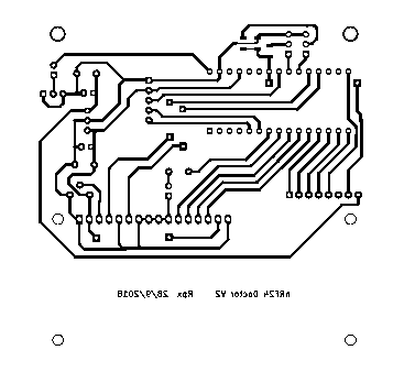
And a pcb, not so beautiful and compact than yours, but "Home made" 85x85mm single side with four straps.Anyway, I have one question, if the github nRF24DoctorGateway.ino compile correctly,
the nRF24DoctorNode.ino produce one error :/sketchbook/nRF24DoctorNode/nRF24DoctorNode.ino: In function 'void statemachine()':nRF24DoctorNode:566: error: 'RF24_getReceivedPowerDetector' was not declared in this scope
if (RF24_getReceivedPowerDetector())
^
If I comment this line, it compile correctly.What's wrong ?
Rpx
-
Done ! With your great help on github, I made one nRF24DoctorNode.
Some modifications : Battery powering with two LiIon from laptop, for 7.5 v on Arduino Nano Raw
The 1117 of Nano out 5.0v for Nano, LCD1602 and KY040 Rotary Encoder.
Finally the 5.0v powers a LE33 to produce 3.3v for nRF24.
Resistors smd, led and mosFETs (I try 40N03) are "second hand parts".
With your PDF schematics I redraw à nRF24DoctorNode with KiKad.
And a pcb, not so beautiful and compact than yours, but "Home made" 85x85mm single side with four straps.Anyway, I have one question, if the github nRF24DoctorGateway.ino compile correctly,
the nRF24DoctorNode.ino produce one error :/sketchbook/nRF24DoctorNode/nRF24DoctorNode.ino: In function 'void statemachine()':nRF24DoctorNode:566: error: 'RF24_getReceivedPowerDetector' was not declared in this scope
if (RF24_getReceivedPowerDetector())
^
If I comment this line, it compile correctly.What's wrong ?
Rpx
@rpx you need the development version of the mySensors library. 2.3.0 doesn't contain the functions for the received power detection graph yet.
The doctor will work with that line commented out, but the graph will stay empty.http://yveaux.blogspot.nl
-
@rpx you need the development version of the mySensors library. 2.3.0 doesn't contain the functions for the received power detection graph yet.
The doctor will work with that line commented out, but the graph will stay empty. -
@Yveaux
Thank you very much for your answer.
I upload nRF24DoctorNode.ino with commented line and ... It work's ! But it don't see any of my three gateways one serial and two Ethernet W5100 which are all on work.
First I have to build a fourth one with the nRF24DoctorGateway.ino sketch.
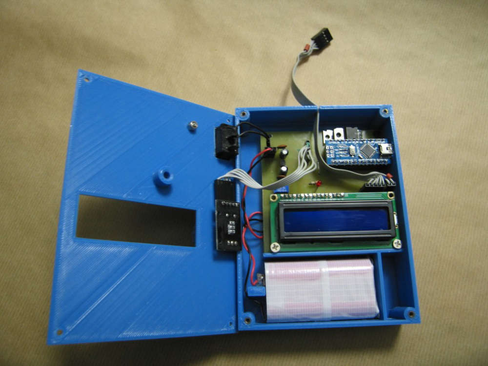
Some photos:
Front
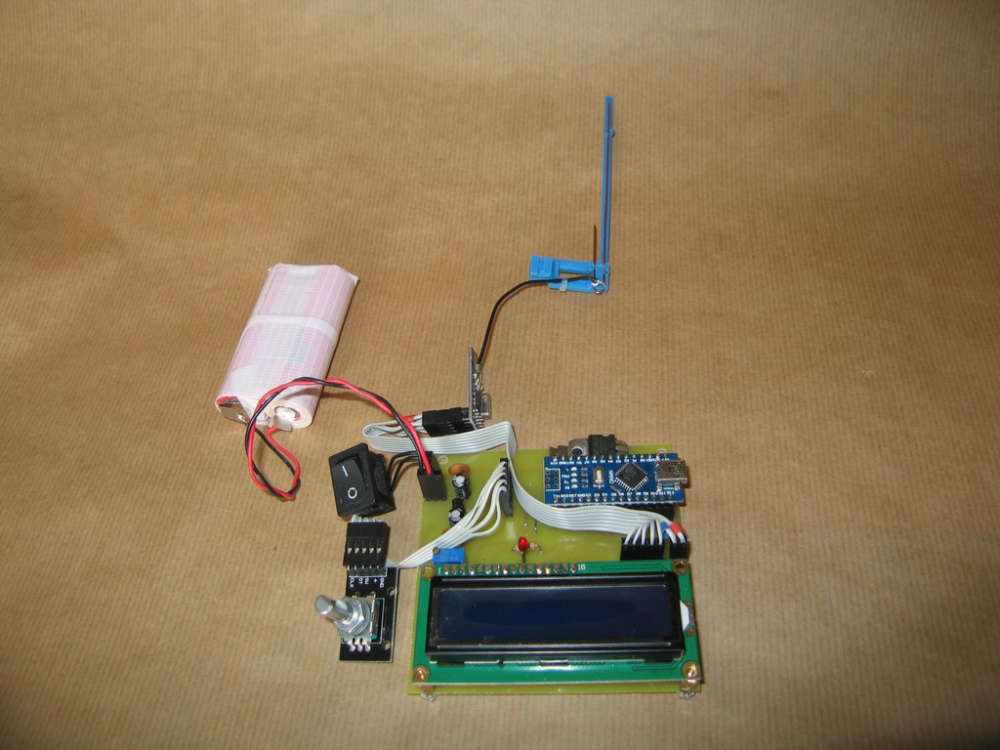
Front without Nano & LCD
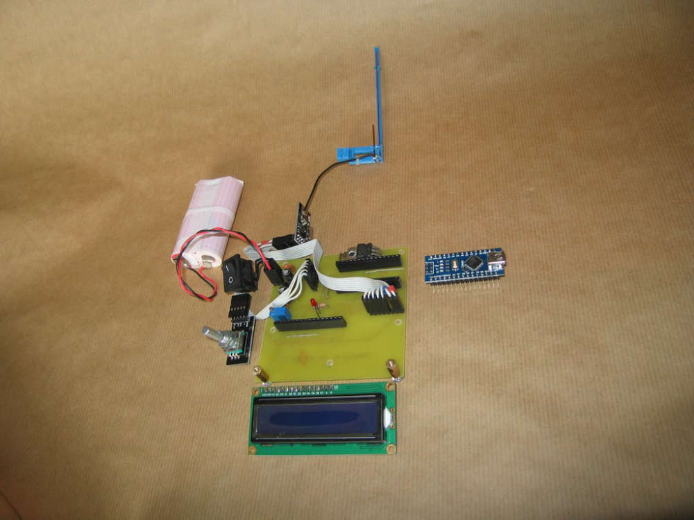
Back
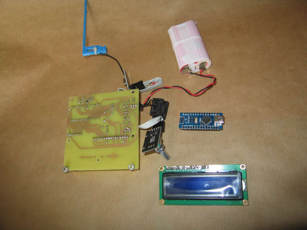
KiKad schematics: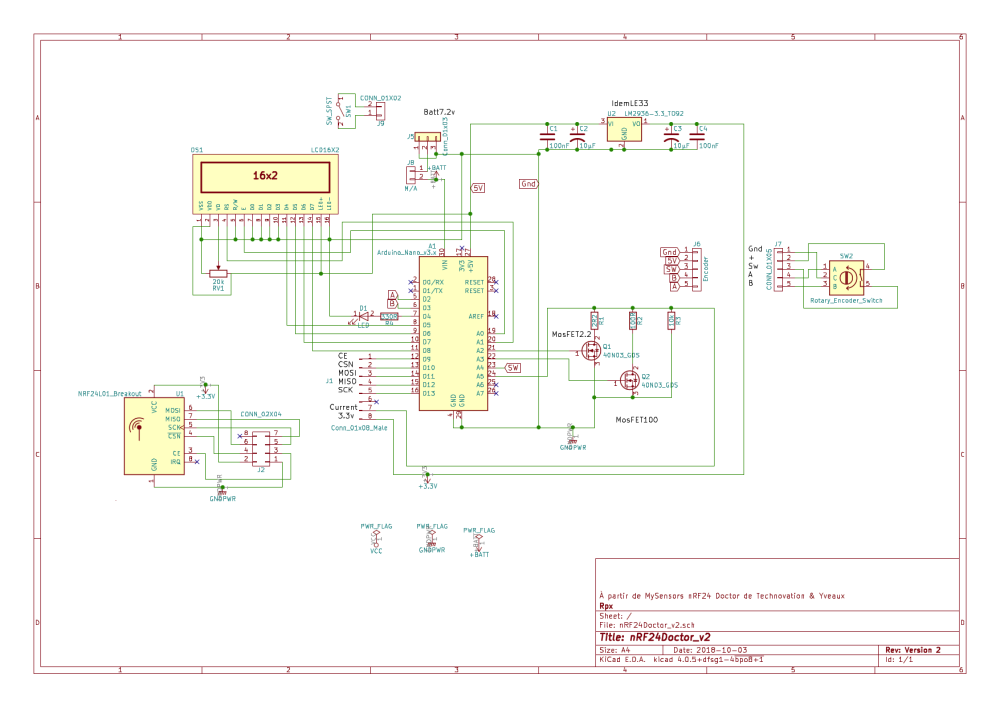
Pcb:
And LCD modifications:For D4 - D7 LCD #define LCD_D7 8 // 5 due to easier pcb design #define LCD_D6 7 // 6 #define LCD_D5 6 // 7 #define LCD_D4 5 // 8At last, I need to build an enclosure...
Rpx.
-
@rpx you need the development version of the mySensors library. 2.3.0 doesn't contain the functions for the received power detection graph yet.
The doctor will work with that line commented out, but the graph will stay empty. -
@yveaux Thanks !
One enclosure later...
I think about my three gateways weren't view.
And made few adjustments.First in RadioConfig.h Ireplace "Zero CaFe BaBe" by my one of MY_RF24_BASE_RADIO_ID
/**
- @def MY_RF24_BASE_RADIO_ID
- @brief RF24 radio network identifier.
- This acts as base value for sensor nodeId addresses. Change this (or channel) if you have more
- than one sensor network.
*/
//0x00,0xCA,0xFE,0xBA,0xBE // modif Rpx de "Zero CaFe BaBe"
Second to be sure force selection of nRF24 CE on D9 and CS on D10
//PIN 9~13: NRF24 RADIO
#define MY_RF24_CE_PIN    (9)
#define MY_RF24_CS_PIN    (10)
And then Doctor is at work!
Enclosure Open
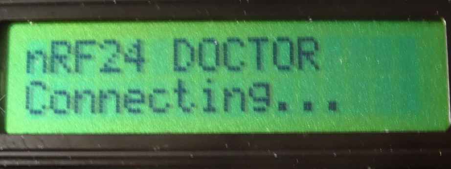
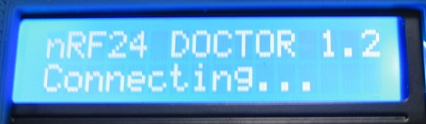
Connecting
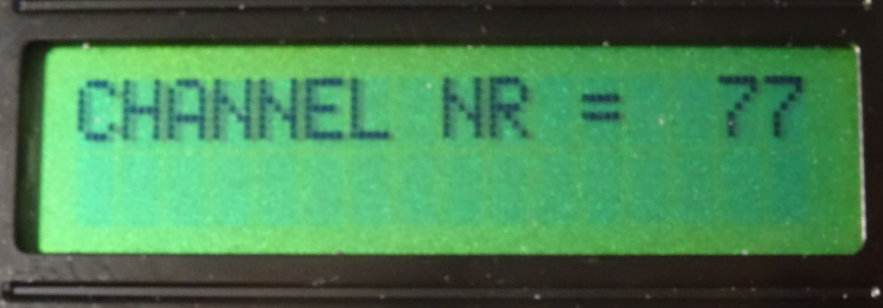
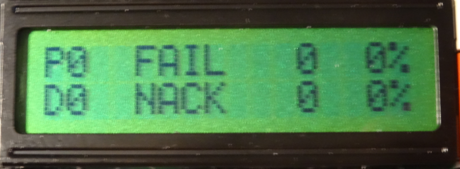
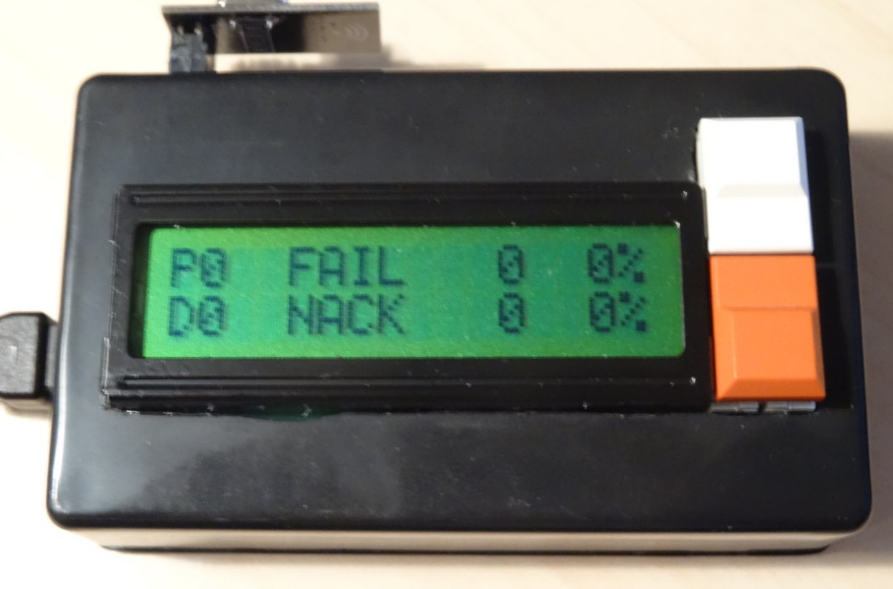
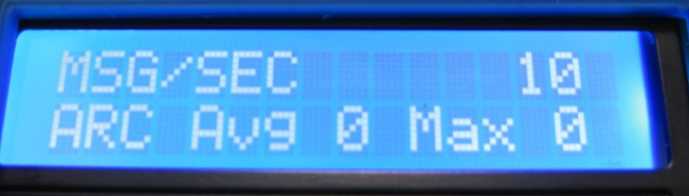
Msg
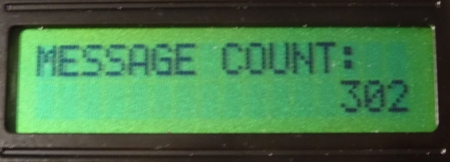
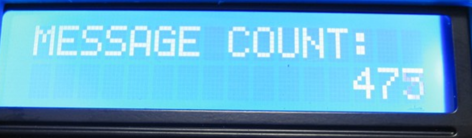
Message Count
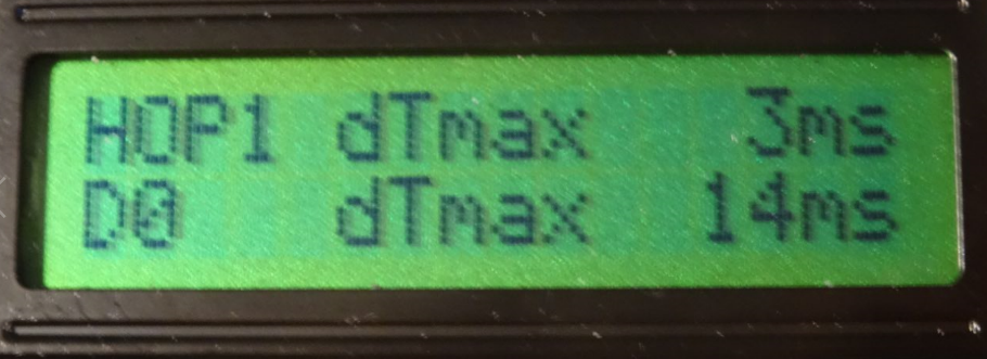
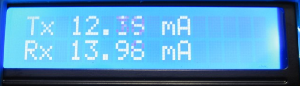
Tx Rx
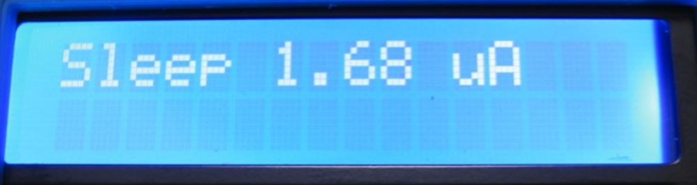
Sleep
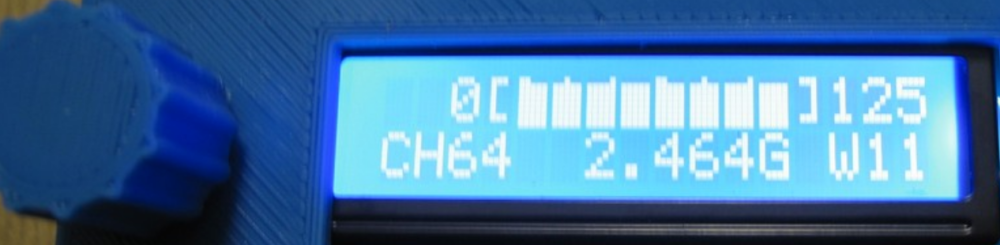
Scan
At last, nRF24Doctor is working. Except scan due I think to use MySensors Library 2.2.0.
I don't know if a nRF24 PA LNA (20dBm) can be tested with nRF24Doctor but if my circuit design is used you should change LE33 witch output max 100mA because nRF24 PA LNA need 150mA min.
And one problem, a test with nRF24Doctor "freeze" Domoticz 3.8153, I need to stop service Domoticz and start to have a Domoticz web access.Thank you very much Yveaux.
Rpx. -
@yveaux Thanks !
One enclosure later...
I think about my three gateways weren't view.
And made few adjustments.First in RadioConfig.h Ireplace "Zero CaFe BaBe" by my one of MY_RF24_BASE_RADIO_ID
/**
- @def MY_RF24_BASE_RADIO_ID
- @brief RF24 radio network identifier.
- This acts as base value for sensor nodeId addresses. Change this (or channel) if you have more
- than one sensor network.
*/
//0x00,0xCA,0xFE,0xBA,0xBE // modif Rpx de "Zero CaFe BaBe"
Second to be sure force selection of nRF24 CE on D9 and CS on D10
//PIN 9~13: NRF24 RADIO
#define MY_RF24_CE_PIN    (9)
#define MY_RF24_CS_PIN    (10)
And then Doctor is at work!
Enclosure Open
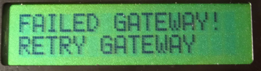
Connecting
Msg
Message Count
Tx Rx
Sleep
Scan
At last, nRF24Doctor is working. Except scan due I think to use MySensors Library 2.2.0.
I don't know if a nRF24 PA LNA (20dBm) can be tested with nRF24Doctor but if my circuit design is used you should change LE33 witch output max 100mA because nRF24 PA LNA need 150mA min.
And one problem, a test with nRF24Doctor "freeze" Domoticz 3.8153, I need to stop service Domoticz and start to have a Domoticz web access.Thank you very much Yveaux.
Rpx.@rpx
@Yveaux OK with a nRF24 gateway it's working fine. But, and I don't remember why, I need to strap pin 8 of nRF24L01+ (Irq) to Nano Pin D2, which is not required on mysensors gateways.
And with MySensors Library 2.3.0 beta Scan is working.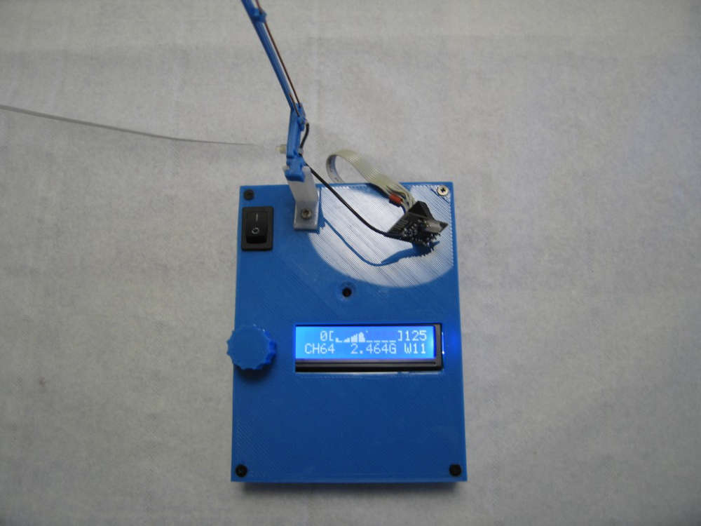
This pattern is a 950W microwave owen near by 0,60 meter.
The graph has 8 pixel high, can you give me a idea of the power scale of each pixel ?And I plan with friends help, to measure differents antennas in open field as J pole, Yagi-Uda and cloverleaf.
Rpx. -
@rpx
@Yveaux OK with a nRF24 gateway it's working fine. But, and I don't remember why, I need to strap pin 8 of nRF24L01+ (Irq) to Nano Pin D2, which is not required on mysensors gateways.
And with MySensors Library 2.3.0 beta Scan is working.
This pattern is a 950W microwave owen near by 0,60 meter.
The graph has 8 pixel high, can you give me a idea of the power scale of each pixel ?And I plan with friends help, to measure differents antennas in open field as J pole, Yagi-Uda and cloverleaf.
Rpx.@rpx said in nRF24Doctor:
The graph has 8 pixel high, can you give me a idea of the power scale of each pixel
Each time a carrier is detected on a channel the count for the channel is increased by 1, with a maximum of 255 per channel (per bucket really).
The top pixel of the chart gets set when the value is 128 or above, the next when 64 or above, then 32 etc. So kind of log2 logarithmic.
It makes the chart sensitive to small counts, but also displays larger values. -
@rpx said in nRF24Doctor:
The graph has 8 pixel high, can you give me a idea of the power scale of each pixel
Each time a carrier is detected on a channel the count for the channel is increased by 1, with a maximum of 255 per channel (per bucket really).
The top pixel of the chart gets set when the value is 128 or above, the next when 64 or above, then 32 etc. So kind of log2 logarithmic.
It makes the chart sensitive to small counts, but also displays larger values.This code is just great, Very good and impressive job.
While looking after recommendations for improving reliability of NRF24 links on easydomoticz french forum, @rpx put me through your NRFDoctor and I must admit is exceeds my expectations.
I just built it in few days and just starting to use it.
Tx/Rx statistic, Icc current measurements in sleep and operating modes, capabilities to reconfigure radio parameters between node and gateway, without forgeting the beautifull frequency range bar graph.
A perfect tool for Wifi and NRF links.
Many Thanks and regards