GUIDE - NRF5 / NRF51 / NRF52 for beginners
-
@ileneken3 What I meant was just export your .hex file and then drop it on the virtual JLINK drive to do the chip programming, not try to burn it directly from the IDE. That way you only depend on the DK doing it's job, not on an arduino IDE, where some versions don't seem to work well. Anyhow, that's how I do it now, and, at least for me, it seems to work the most reliably.
That said, I haven't tried the E73-2G4M04S1B, so can't really say regarding that one specifically. On the inside they should all be the same chip though, so I'm surprised to hear that it may have different requirements.
These days I'm largely focused on the nRF52840 and driving it with Forth. Maybe later I may circle back to the 832.
Yes, I understood what you meant. I will only do the "Export compiled Binary" from the IDE, and leave the drivers as J-Link commander or nrfGo Studio wants them.
In: https://www.openhardware.io/view/376/MySensors-NRF5-Platform it says:
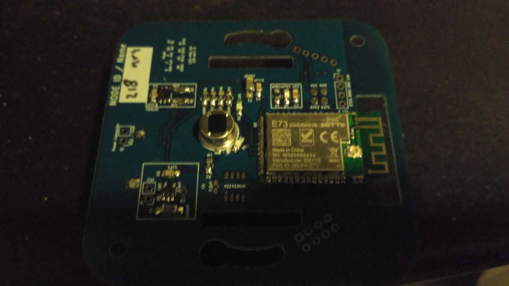
"Currently, the nRF52832 and nRF51822 are supported so we recommend sticking with those for now."I noticed that my board: (E73-2G4M04S) is labeled "NRF52810". So is that why after programming it nothing works (nothing seen on gateway) :( ?
If so, I messed up on that order.
But I am also trying the E73 2G4M04S1B, which at least from the AliExpress order
https://www.aliexpress.com/item/CDEBYTE-E73-2G4M04S-BLE-4-2-5-0-long-distance-100m-2-4GHz-SMD-ARM-Core/32820692238.html?spm=a2g0s.9042311.0.0.27424c4dSKBLn7says it is nRF52832. (It isn't labeled on the board though). For this module, I can't unlock it using "Recover" from nRfgoStudio. It always fails with a message "Recover failed: Unknown error".
From the command line, if I do
nrfjprog.exe -f NRF52 --recover --log
and it comes back immediately with:
Recovering device. This operation might take 30s.
ERROR: Recover failed. Please make sure that the correct device family is given
ERROR: and try again.The key error from the log seems to be:
2018-Dec-27 12:25:22 . . . . . nRF52_power_debug_and_system_regions
2018-Dec-27 12:25:22 . . . . . . nRF52_write_debug_port_register
2018-Dec-27 12:25:22 . . . . . . nRF52_write_debug_port_register: JLink: JLINK_CORESIGHT_WriteAPDPReg(DP reg 0x02, 0x00000000)
2018-Dec-27 12:25:22 . . . . . . nRF52_write_debug_port_register: JLink: returns -1
2018-Dec-27 12:25:23 . . . . . . nRF52_write_debug_port_register: JLink: (0005ms, 0288ms total)
2018-Dec-27 12:25:23 . . . . . . nRF52_write_debug_port_register: JLinkARM.dll CORESIGHT_WriteAPDPReg returned error -1.2018-Dec-27 12:25:23 . . . . . nRF52_power_debug_and_system_regions: JLinkARM.dll CORESIGHT_WriteAPDPReg returned error -102.
If I do: nrfjprog.exe -f NRF51 --recover --log
it actually makes LD5 on the DK board flash for 30 seconds, but still returns failure with the exact same message.
Any other tricks for "recover/unlock" of those boards?
Thanks!
-
Yes, I understood what you meant. I will only do the "Export compiled Binary" from the IDE, and leave the drivers as J-Link commander or nrfGo Studio wants them.
In: https://www.openhardware.io/view/376/MySensors-NRF5-Platform it says:
"Currently, the nRF52832 and nRF51822 are supported so we recommend sticking with those for now."I noticed that my board: (E73-2G4M04S) is labeled "NRF52810". So is that why after programming it nothing works (nothing seen on gateway) :( ?
If so, I messed up on that order.
But I am also trying the E73 2G4M04S1B, which at least from the AliExpress order
https://www.aliexpress.com/item/CDEBYTE-E73-2G4M04S-BLE-4-2-5-0-long-distance-100m-2-4GHz-SMD-ARM-Core/32820692238.html?spm=a2g0s.9042311.0.0.27424c4dSKBLn7says it is nRF52832. (It isn't labeled on the board though). For this module, I can't unlock it using "Recover" from nRfgoStudio. It always fails with a message "Recover failed: Unknown error".
From the command line, if I do
nrfjprog.exe -f NRF52 --recover --log
and it comes back immediately with:
Recovering device. This operation might take 30s.
ERROR: Recover failed. Please make sure that the correct device family is given
ERROR: and try again.The key error from the log seems to be:
2018-Dec-27 12:25:22 . . . . . nRF52_power_debug_and_system_regions
2018-Dec-27 12:25:22 . . . . . . nRF52_write_debug_port_register
2018-Dec-27 12:25:22 . . . . . . nRF52_write_debug_port_register: JLink: JLINK_CORESIGHT_WriteAPDPReg(DP reg 0x02, 0x00000000)
2018-Dec-27 12:25:22 . . . . . . nRF52_write_debug_port_register: JLink: returns -1
2018-Dec-27 12:25:23 . . . . . . nRF52_write_debug_port_register: JLink: (0005ms, 0288ms total)
2018-Dec-27 12:25:23 . . . . . . nRF52_write_debug_port_register: JLinkARM.dll CORESIGHT_WriteAPDPReg returned error -1.2018-Dec-27 12:25:23 . . . . . nRF52_power_debug_and_system_regions: JLinkARM.dll CORESIGHT_WriteAPDPReg returned error -102.
If I do: nrfjprog.exe -f NRF51 --recover --log
it actually makes LD5 on the DK board flash for 30 seconds, but still returns failure with the exact same message.
Any other tricks for "recover/unlock" of those boards?
Thanks!
@ileneken3 I suggest posting a query on the nordic devzone forum. A Nordic engineer will get assigned to it and give you an answer. I've tried this a few times, and I had good luck with it. Generally 24 hour turnaround on weekdays, and no answers on weekends. So, if you post it now, you may get an answer tomorrow. It's in Nordic's interest to help developers unlock these chips, and if there are any secrets to doing so, Nordic will certainly know them.
It sounds as though once you get past the unlock issue, it will be easier for you.
-
Yes, I understood what you meant. I will only do the "Export compiled Binary" from the IDE, and leave the drivers as J-Link commander or nrfGo Studio wants them.
In: https://www.openhardware.io/view/376/MySensors-NRF5-Platform it says:
"Currently, the nRF52832 and nRF51822 are supported so we recommend sticking with those for now."I noticed that my board: (E73-2G4M04S) is labeled "NRF52810". So is that why after programming it nothing works (nothing seen on gateway) :( ?
If so, I messed up on that order.
But I am also trying the E73 2G4M04S1B, which at least from the AliExpress order
https://www.aliexpress.com/item/CDEBYTE-E73-2G4M04S-BLE-4-2-5-0-long-distance-100m-2-4GHz-SMD-ARM-Core/32820692238.html?spm=a2g0s.9042311.0.0.27424c4dSKBLn7says it is nRF52832. (It isn't labeled on the board though). For this module, I can't unlock it using "Recover" from nRfgoStudio. It always fails with a message "Recover failed: Unknown error".
From the command line, if I do
nrfjprog.exe -f NRF52 --recover --log
and it comes back immediately with:
Recovering device. This operation might take 30s.
ERROR: Recover failed. Please make sure that the correct device family is given
ERROR: and try again.The key error from the log seems to be:
2018-Dec-27 12:25:22 . . . . . nRF52_power_debug_and_system_regions
2018-Dec-27 12:25:22 . . . . . . nRF52_write_debug_port_register
2018-Dec-27 12:25:22 . . . . . . nRF52_write_debug_port_register: JLink: JLINK_CORESIGHT_WriteAPDPReg(DP reg 0x02, 0x00000000)
2018-Dec-27 12:25:22 . . . . . . nRF52_write_debug_port_register: JLink: returns -1
2018-Dec-27 12:25:23 . . . . . . nRF52_write_debug_port_register: JLink: (0005ms, 0288ms total)
2018-Dec-27 12:25:23 . . . . . . nRF52_write_debug_port_register: JLinkARM.dll CORESIGHT_WriteAPDPReg returned error -1.2018-Dec-27 12:25:23 . . . . . nRF52_power_debug_and_system_regions: JLinkARM.dll CORESIGHT_WriteAPDPReg returned error -102.
If I do: nrfjprog.exe -f NRF51 --recover --log
it actually makes LD5 on the DK board flash for 30 seconds, but still returns failure with the exact same message.
Any other tricks for "recover/unlock" of those boards?
Thanks!
@ileneken3 sorry, can't help you anymore.
I can only tell that I installed the segger drivers, and everything as described by @d00616
Most issues I have, happen when I did some soldering wrong or when I've been messing around with drivers. A clean setup almost always solve my problems
I used both old and new ebyte modules and they work like a charm.
-
Hi,
I'm trying to begin with nrf52832.
I have follow advice, with soldering 4 wires. I use STlink v2, downloading soft before use it.
When i try to erase the nrf52832, with sketch "mass_erase" in exemple, i have the following error :Arduino : 1.8.7 (Windows 10), Carte : "MyBoardNRF5 nRF52832, None, Crystal Oscillator, Don't enable"
C:\Users\Sancho\AppData\Local\Arduino15\packages\sandeepmistry\tools\openocd\0.10.0-dev.nrf5/bin/openocd.exe -d2 -f interface/stlink-v2.cfg -c transport select hla_swd; set WORKAREASIZE 0x4000; -f target/nrf52.cfg -c init; halt; nrf51 mass_erase; program {{{build.core.path}/SDK/components/softdevice/none/hex/none_nrf52_{softdeviceversion}_softdevice.hex}} verify reset; shutdown;
Open On-Chip Debugger 0.10.0-dev-00254-g696fc0a (2016-04-10-10:13)
Licensed under GNU GPL v2
For bug reports, read
http://openocd.org/doc/doxygen/bugs.html
debug_level: 2
0x4000
Info : The selected transport took over low-level target control. The results might differ compared to plain JTAG/SWD
adapter speed: 10000 kHz
Info : Unable to match requested speed 10000 kHz, using 4000 kHz
Info : Unable to match requested speed 10000 kHz, using 4000 kHz
Info : clock speed 4000 kHz
Info : STLINK v2 JTAG v29 API v2 SWIM v7 VID 0x0483 PID 0x3748
Info : using stlink api v2
Info : Target voltage: 3.280426
Error: init mode failed (unable to connect to the target)
in procedure 'init'
in procedure 'ocd_bouncer'Erreur lors de la gravure de la séquence d'initialisation.
I try to upload an empty sketch (MyBoardNRF5), and have this message :
Arduino : 1.8.7 (Windows 10), Carte : "MyBoardNRF5 nRF52832, None, Crystal Oscillator, Don't enable"
Le croquis utilise 10508 octets (2%) de l'espace de stockage de programmes. Le maximum est de 524288 octets.
C:\Users\Sancho\AppData\Local\Arduino15\packages\sandeepmistry\tools\openocd\0.10.0-dev.nrf5/bin/openocd.exe -d2 -f interface/stlink-v2.cfg -c transport select hla_swd; set WORKAREASIZE 0x4000; -f target/nrf52.cfg -c program {{C:\Users\Sancho\AppData\Local\Temp\arduino_build_74329/MyBoardNRF5.ino.hex}} verify reset; shutdown;
Open On-Chip Debugger 0.10.0-dev-00254-g696fc0a (2016-04-10-10:13)
Licensed under GNU GPL v2
For bug reports, read
http://openocd.org/doc/doxygen/bugs.html
debug_level: 2
0x4000
Info : The selected transport took over low-level target control. The results might differ compared to plain JTAG/SWD
adapter speed: 10000 kHz
Une erreur est survenue lors du transfert du croquis
Info : Unable to match requested speed 10000 kHz, using 4000 kHz
Info : Unable to match requested speed 10000 kHz, using 4000 kHz
Info : clock speed 4000 kHz
Info : STLINK v2 JTAG v29 API v2 SWIM v7 VID 0x0483 PID 0x3748
Info : using stlink api v2
Info : Target voltage: 3.280426
Error: init mode failed (unable to connect to the target)
in procedure 'program'
in procedure 'init' called at file "embedded:startup.tcl", line 473
in procedure 'ocd_bouncer'
** OpenOCD init failed **
shutdown command invokedCan you help me please ?
@sancho119 what exact model of a board do you have? Did you try to switch SWDIO and SWCLK, maybe they are messed up? Or lose connection? To erase softdevice you can simply chose Tools>Softdevice>"None" and then press "Burn bootloader" button.
-
Hello
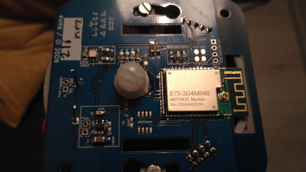
it's a E73 2G4M04S1B from EBYTE
When i switch SWDIO and SWCLK, i can see the led of STLink V2 changing from red to blue, but when i try to uplod empty sketch (MyBoardNRF5), i have this error :C:\Users\Sancho\AppData\Local\Arduino15\packages\sandeepmistry\tools\openocd\0.10.0-dev.nrf5/bin/openocd.exe -d2 -f interface/stlink-v2.cfg -c transport select hla_swd; set WORKAREASIZE 0x4000; -f target/nrf52.cfg -c program {{C:\Users\Sancho\AppData\Local\Temp\arduino_build_432557/MyBoardNRF5.ino.hex}} verify reset; shutdown;
Open On-Chip Debugger 0.10.0-dev-00254-g696fc0a (2016-04-10-10:13)
Licensed under GNU GPL v2
For bug reports, read
http://openocd.org/doc/doxygen/bugs.html
debug_level: 2
0x4000
Info : The selected transport took over low-level target control. The results might differ compared to plain JTAG/SWD
adapter speed: 10000 kHz
Info : Unable to match requested speed 10000 kHz, using 4000 kHz
Info : Unable to match requested speed 10000 kHz, using 4000 kHz
Info : clock speed 4000 kHz
Info : STLINK v2 JTAG v29 API v2 SWIM v7 VID 0x0483 PID 0x3748
Info : using stlink api v2
Info : Target voltage: 3.283200
Info : nrf52.cpu: hardware has 0 breakpoints, 2 watchpoints
Error: timed out while waiting for target halted
TARGET: nrf52.cpu - Not halted
in procedure 'program'
in procedure 'reset' called at file "embedded:startup.tcl", line 478
in procedure 'ocd_bouncer'embedded:startup.tcl:454: Error: ** Unable to reset target **
in procedure 'program'
in procedure 'program_error' called at file "embedded:startup.tcl", line 479
at file "embedded:startup.tcl", line 454
le port série sélectionné at file "embedded:startup.tcl", line 454
n'existe pas ou votre Arduino n'est pas connectée -
Hello
it's a E73 2G4M04S1B from EBYTE
When i switch SWDIO and SWCLK, i can see the led of STLink V2 changing from red to blue, but when i try to uplod empty sketch (MyBoardNRF5), i have this error :C:\Users\Sancho\AppData\Local\Arduino15\packages\sandeepmistry\tools\openocd\0.10.0-dev.nrf5/bin/openocd.exe -d2 -f interface/stlink-v2.cfg -c transport select hla_swd; set WORKAREASIZE 0x4000; -f target/nrf52.cfg -c program {{C:\Users\Sancho\AppData\Local\Temp\arduino_build_432557/MyBoardNRF5.ino.hex}} verify reset; shutdown;
Open On-Chip Debugger 0.10.0-dev-00254-g696fc0a (2016-04-10-10:13)
Licensed under GNU GPL v2
For bug reports, read
http://openocd.org/doc/doxygen/bugs.html
debug_level: 2
0x4000
Info : The selected transport took over low-level target control. The results might differ compared to plain JTAG/SWD
adapter speed: 10000 kHz
Info : Unable to match requested speed 10000 kHz, using 4000 kHz
Info : Unable to match requested speed 10000 kHz, using 4000 kHz
Info : clock speed 4000 kHz
Info : STLINK v2 JTAG v29 API v2 SWIM v7 VID 0x0483 PID 0x3748
Info : using stlink api v2
Info : Target voltage: 3.283200
Info : nrf52.cpu: hardware has 0 breakpoints, 2 watchpoints
Error: timed out while waiting for target halted
TARGET: nrf52.cpu - Not halted
in procedure 'program'
in procedure 'reset' called at file "embedded:startup.tcl", line 478
in procedure 'ocd_bouncer'embedded:startup.tcl:454: Error: ** Unable to reset target **
in procedure 'program'
in procedure 'program_error' called at file "embedded:startup.tcl", line 479
at file "embedded:startup.tcl", line 454
le port série sélectionné at file "embedded:startup.tcl", line 454
n'existe pas ou votre Arduino n'est pas connectée@sancho119 No matter what I tried, I could not unlock the E73 with the STLink.
I had to buy a jlink clone, download a bunch of segger debugging tools, use the segger tools to override the lock flag. After that I could flash the bootloader.
https://github.com/micooke/arduino-nRF5-smartwatches/blob/master/nrf52_disable_read_protection.txt
#To share my experience with the nRF52832. #I was unable to disable the read protection / flash lock with a BMP or ST-Link V2, but i was successful with a J-Link. #When nRF52832 chip is read protected / locked, the first step is to try: nrfjprog –recover -f nrf52 #This performs the same task as: Jlink -if swd -device nrf52 J-Link>SWDSelect J-Link>SWDWriteDP 1, 0x50000000 J-Link>SWDWriteDP 2, 0x01000000 J-Link>SWDWriteAP 1, 0x00000001 #Wait until AP 2 is 0, and the operation is complete J-Link>SWDReadAP 2 #If two successive reads from AP 3 produce 0, then 1 then protection is disabled J-Link>SWDReadAP 3 J-Link>SWDReadAP 3 #Tested with JLink v6.20b -
@sancho119 No matter what I tried, I could not unlock the E73 with the STLink.
I had to buy a jlink clone, download a bunch of segger debugging tools, use the segger tools to override the lock flag. After that I could flash the bootloader.
https://github.com/micooke/arduino-nRF5-smartwatches/blob/master/nrf52_disable_read_protection.txt
#To share my experience with the nRF52832. #I was unable to disable the read protection / flash lock with a BMP or ST-Link V2, but i was successful with a J-Link. #When nRF52832 chip is read protected / locked, the first step is to try: nrfjprog –recover -f nrf52 #This performs the same task as: Jlink -if swd -device nrf52 J-Link>SWDSelect J-Link>SWDWriteDP 1, 0x50000000 J-Link>SWDWriteDP 2, 0x01000000 J-Link>SWDWriteAP 1, 0x00000001 #Wait until AP 2 is 0, and the operation is complete J-Link>SWDReadAP 2 #If two successive reads from AP 3 produce 0, then 1 then protection is disabled J-Link>SWDReadAP 3 J-Link>SWDReadAP 3 #Tested with JLink v6.20b -
-
Hello,
Some news !
i buy a Jlink, and success in erase my nrf52832 with nrf prog, using method of berkseo.Next i try to upload a basic sketch (blink) :
#define MY_RADIO_NRF5_ESB
#include <nrf.h>
#include <MySensors.h>void setup() {
Serial.begin(9600);
hwPinMode(LED_BUILTIN,OUTPUT_H0H1);
}void loop() {
digitalWrite(LED_BUILTIN, HIGH); // turn the LED on (HIGH is the voltage level)
delay(1000); // wait for a second
digitalWrite(LED_BUILTIN, LOW); // turn the LED off by making the voltage LOW
delay(1000); // wait for a second
}I have this :
Open On-Chip Debugger 0.10.0-dev-00254-g696fc0a (2016-04-10-10:13)
Licensed under GNU GPL v2
For bug reports, read
http://openocd.org/doc/doxygen/bugs.html
debug_level: 2
0
adapter speed: 10000 kHz
cortex_m reset_config sysresetreq
Info : No device selected, using first device.
Info : J-Link ARM-OB STM32 compiled Aug 22 2012 19:52:04
Info : Hardware version: 7.00
Info : VTarget = 3.300 V
Info : clock speed 10000 kHz
Info : SWD IDCODE 0x2ba01477
Info : nrf52.cpu: hardware has 6 breakpoints, 4 watchpoints
nrf52.cpu: target state: halted
target halted due to debug-request, current mode: Thread
xPSR: 0x01000000 pc: 0x0000051c msp: 0x20010000
** Programming Started **
auto erase enabled
Warn : Unknown device (HWID 0x00000139)
Warn : not enough working area available(requested 32)
Warn : no working area available, falling back to slow memory writes
wrote 12288 bytes from file C:\Users\Sancho\AppData\Local\Temp\arduino_build_76789/NRF5_blink_led8.ino.hex in 4.155332s (2.888 KiB/s)
** Programming Finished **
** Verify Started **
Warn : not enough working area available(requested 52)
verified 10812 bytes in 0.165932s (63.632 KiB/s)
** Verified OK **
** Resetting Target **
shutdown command invokedI think its good, but when i put a led with a resistance on P0.08, nothing :(
could you help me more ?
@sancho119 said in GUIDE - NRF5 / NRF51 / NRF52 for beginners:
Hello,
Some news !
i buy a Jlink, and success in erase my nrf52832 with nrf prog, using method of berkseo.Next i try to upload a basic sketch (blink) :
#define MY_RADIO_NRF5_ESB
#include <nrf.h>
#include <MySensors.h>void setup() {
Serial.begin(9600);
hwPinMode(LED_BUILTIN,OUTPUT_H0H1);
}void loop() {
digitalWrite(LED_BUILTIN, HIGH); // turn the LED on (HIGH is the voltage level)
delay(1000); // wait for a second
digitalWrite(LED_BUILTIN, LOW); // turn the LED off by making the voltage LOW
delay(1000); // wait for a second
}I have this :
Open On-Chip Debugger 0.10.0-dev-00254-g696fc0a (2016-04-10-10:13)
Licensed under GNU GPL v2
For bug reports, read
http://openocd.org/doc/doxygen/bugs.html
debug_level: 2
0
adapter speed: 10000 kHz
cortex_m reset_config sysresetreq
Info : No device selected, using first device.
Info : J-Link ARM-OB STM32 compiled Aug 22 2012 19:52:04
Info : Hardware version: 7.00
Info : VTarget = 3.300 V
Info : clock speed 10000 kHz
Info : SWD IDCODE 0x2ba01477
Info : nrf52.cpu: hardware has 6 breakpoints, 4 watchpoints
nrf52.cpu: target state: halted
target halted due to debug-request, current mode: Thread
xPSR: 0x01000000 pc: 0x0000051c msp: 0x20010000
** Programming Started **
auto erase enabled
Warn : Unknown device (HWID 0x00000139)
Warn : not enough working area available(requested 32)
Warn : no working area available, falling back to slow memory writes
wrote 12288 bytes from file C:\Users\Sancho\AppData\Local\Temp\arduino_build_76789/NRF5_blink_led8.ino.hex in 4.155332s (2.888 KiB/s)
** Programming Finished **
** Verify Started **
Warn : not enough working area available(requested 52)
verified 10812 bytes in 0.165932s (63.632 KiB/s)
** Verified OK **
** Resetting Target **
shutdown command invokedI think its good, but when i put a led with a resistance on P0.08, nothing :(
could you help me more ?
LED_BUILTIN corresponds to po17
-
-
Hi. Are the steps in first post still valid please?
I'm trying without luck to get first nrf52 programmed. I get a weird error"Error resolving FQBN: missing" in Arduino IDE when I try to verify any basic sketch, even blink. Thanks for any thoughts
-
@p359 Which version of Arduino IDE are you using? I was seeing that with 1.8.10, but I ended up downgrading to 1.8.6 to test and it worked.
-
Hi,
Is it possible to get Serial output in Arduino IDE for nRF52 boards with J-Link OB 7.0? Or do I need a newer programmer? Or maybe I can get it with ST-Link v2/v2.1 somehow?
@martinc said in GUIDE - NRF5 / NRF51 / NRF52 for beginners:
Hi,
Is it possible to get Serial output in Arduino IDE for nRF52 boards with J-Link OB 7.0? Or do I need a newer programmer? Or maybe I can get it with ST-Link v2/v2.1 somehow?
The answer is actually in the first post.
-
@alowhum said in GUIDE - NRF5 / NRF51 / NRF52 for beginners:
The answer is actually in the first post.
Thanks, I've seen it before. In my case a programmer is easier solution - I don't know yet how to re-assign TX&RX pins in Arduino on my EByte 52840 module and in specs for that module there is no info about UART connectivity.
Maybe you know how can I re-assign TX&RX pins in Arduino? Then I can solder wires to assigned TX&RX pins and connect them to USB-UART. What I've found is in Forth language ... -
Does anyone know what settings I need to use for this development board with arduino ide?
Ebyte E104-BT5032A-TB
https://a.aliexpress.com/_dT5dMb8It has a cp2102 on board which I have the driver for. I've installed the arduino ide nrf52 board, but I can't find a programmer, board, or any other settings which will let me flash it without a Java exception or a timeout. Maybe I need to set the jumpers differently but there's no documentation on that.
OTA works fine though.
Hello! It looks like you're interested in this conversation, but you don't have an account yet.
Getting fed up of having to scroll through the same posts each visit? When you register for an account, you'll always come back to exactly where you were before, and choose to be notified of new replies (either via email, or push notification). You'll also be able to save bookmarks and upvote posts to show your appreciation to other community members.
With your input, this post could be even better 💗
Register Login