Skip to content
  • MySensors
  • OpenHardware.io
  • Categories
  • Recent
  • Tags
  • Popular
Skins
  • Light
  • Brite
  • Cerulean
  • Cosmo
  • Flatly
  • Journal
  • Litera
  • Lumen
  • Lux
  • Materia
  • Minty
  • Morph
  • Pulse
  • Sandstone
  • Simplex
  • Sketchy
  • Spacelab
  • United
  • Yeti
  • Zephyr
  • Dark
  • Cyborg
  • Darkly
  • Quartz
  • Slate
  • Solar
  • Superhero
  • Vapor

  • Default (No Skin)
  • No Skin
Collapse
Brand Logo
  1. Home
  2. Development
  3. GUIDE - NRF5 / NRF51 / NRF52 for beginners

GUIDE - NRF5 / NRF51 / NRF52 for beginners

Scheduled Pinned Locked Moved Development
102 Posts 26 Posters 18.2k Views 26 Watching
  • Oldest to Newest
  • Newest to Oldest
  • Most Votes
Reply
  • Reply as topic
Log in to reply
This topic has been deleted. Only users with topic management privileges can see it.
  • N ncollins

    @p359 Which version of Arduino IDE are you using? I was seeing that with 1.8.10, but I ended up downgrading to 1.8.6 to test and it worked.

    P Offline
    P Offline
    p359
    wrote on last edited by
    #42

    @ncollins 1.8.10 also. I'll try then 1.8.6 tonight. Cheers for the idea!

    1 Reply Last reply
    0
    • M Offline
      M Offline
      MartinC
      wrote on last edited by
      #43

      Hi,

      Is it possible to get Serial output in Arduino IDE for nRF52 boards with J-Link OB 7.0? Or do I need a newer programmer? Or maybe I can get it with ST-Link v2/v2.1 somehow?

      alowhumA 1 Reply Last reply
      1
      • M MartinC

        Hi,

        Is it possible to get Serial output in Arduino IDE for nRF52 boards with J-Link OB 7.0? Or do I need a newer programmer? Or maybe I can get it with ST-Link v2/v2.1 somehow?

        alowhumA Offline
        alowhumA Offline
        alowhum
        Plugin Developer
        wrote on last edited by
        #44

        @martinc said in GUIDE - NRF5 / NRF51 / NRF52 for beginners:

        Hi,

        Is it possible to get Serial output in Arduino IDE for nRF52 boards with J-Link OB 7.0? Or do I need a newer programmer? Or maybe I can get it with ST-Link v2/v2.1 somehow?

        The answer is actually in the first post.

        1 Reply Last reply
        1
        • M Offline
          M Offline
          MartinC
          wrote on last edited by
          #45

          @alowhum said in GUIDE - NRF5 / NRF51 / NRF52 for beginners:

          The answer is actually in the first post.

          Thanks, I've seen it before. In my case a programmer is easier solution - I don't know yet how to re-assign TX&RX pins in Arduino on my EByte 52840 module and in specs for that module there is no info about UART connectivity.
          Maybe you know how can I re-assign TX&RX pins in Arduino? Then I can solder wires to assigned TX&RX pins and connect them to USB-UART. What I've found is in Forth language ...

          1 Reply Last reply
          0
          • I Offline
            I Offline
            idanronen
            wrote on last edited by
            #46

            Does anyone know what settings I need to use for this development board with arduino ide?
            Ebyte E104-BT5032A-TB
            https://a.aliexpress.com/_dT5dMb8

            It has a cp2102 on board which I have the driver for. I've installed the arduino ide nrf52 board, but I can't find a programmer, board, or any other settings which will let me flash it without a Java exception or a timeout. Maybe I need to set the jumpers differently but there's no documentation on that.
            OTA works fine though.

            Nca78N 2 Replies Last reply
            0
            • I idanronen

              Does anyone know what settings I need to use for this development board with arduino ide?
              Ebyte E104-BT5032A-TB
              https://a.aliexpress.com/_dT5dMb8

              It has a cp2102 on board which I have the driver for. I've installed the arduino ide nrf52 board, but I can't find a programmer, board, or any other settings which will let me flash it without a Java exception or a timeout. Maybe I need to set the jumpers differently but there's no documentation on that.
              OTA works fine though.

              Nca78N Offline
              Nca78N Offline
              Nca78
              Hardware Contributor
              wrote on last edited by
              #47

              @idanronen this is a UART to BT module, and from what I understand in the documentation the CP2102 is only here to give you access to the serial port of the module, but not to program it ?

              To program it you will have to use the SWDIO/SWDCLK pins I suppose, and I'm interested to know if it can be reprogrammed because that would make a tiny NRF52832 module for boards that don't require many IOs.

              I 2 Replies Last reply
              0
              • Nca78N Nca78

                @idanronen this is a UART to BT module, and from what I understand in the documentation the CP2102 is only here to give you access to the serial port of the module, but not to program it ?

                To program it you will have to use the SWDIO/SWDCLK pins I suppose, and I'm interested to know if it can be reprogrammed because that would make a tiny NRF52832 module for boards that don't require many IOs.

                I Offline
                I Offline
                idanronen
                wrote on last edited by
                #48

                @Nca78 I feared that might be the case. my task for today was to dig up my st-link and try that, though I hoped I might have done something wrong and the cp2102 can be used to program and not just debug.
                That module is pretty cheap and from what I see with the naked eye, you can disconnect the cp2102 with the jumpers so the power consumption might actually be good enough to use as-is.
                I'll report back to let you know once I've succeeded

                1 Reply Last reply
                1
                • A Offline
                  A Offline
                  Avamander
                  wrote on last edited by Avamander
                  #49

                  I tried flashing MySensors onto my nRF52840 Adafruit Feather board but it fails, I opened an issue on GH about it https://github.com/mysensors/MySensors/issues/1424, maybe someone here has any ideas how to get it running on those boards?

                  1 Reply Last reply
                  0
                  • Nca78N Nca78

                    @idanronen this is a UART to BT module, and from what I understand in the documentation the CP2102 is only here to give you access to the serial port of the module, but not to program it ?

                    To program it you will have to use the SWDIO/SWDCLK pins I suppose, and I'm interested to know if it can be reprogrammed because that would make a tiny NRF52832 module for boards that don't require many IOs.

                    I Offline
                    I Offline
                    idanronen
                    wrote on last edited by idanronen
                    #50

                    @Nca78 no luck with the st-link v2, though i doubt it is related to the board, but rather my inability. i've tried every option in zadig, installed the st-link driver from their website, and nothing works.
                    i get this in arduino ide:

                    debug_level: 0
                    0x4000
                    adapter speed: 10000 kHz
                    Error: init mode failed (unable to connect to the target)
                    in procedure 'program' 
                    in procedure 'init' called at file "embedded:startup.tcl", line 473
                    in procedure 'ocd_bouncer'
                    ** OpenOCD init failed **
                    shutdown command invoked
                    
                    the selected serial port 
                     does not exist or your board is not connected
                    
                    1 Reply Last reply
                    0
                    • N Offline
                      N Offline
                      ncollins
                      wrote on last edited by
                      #51

                      With all the NRF52 modules from EBYTE I've tried, the only way I can flash them is over SWDIO, SWCLK, GND, VCC via JLink clone.

                      And, before flashing is possible, I have to unlock the module by following these directions: https://github.com/micooke/arduino-nRF5-smartwatches/blob/master/nrf52_disable_read_protection.txt

                      I 1 Reply Last reply
                      2
                      • N ncollins

                        With all the NRF52 modules from EBYTE I've tried, the only way I can flash them is over SWDIO, SWCLK, GND, VCC via JLink clone.

                        And, before flashing is possible, I have to unlock the module by following these directions: https://github.com/micooke/arduino-nRF5-smartwatches/blob/master/nrf52_disable_read_protection.txt

                        I Offline
                        I Offline
                        idanronen
                        wrote on last edited by
                        #52

                        @ncollins I've been working on turning an stm32f030f4p6 into a blackmagic probe for a few days now. Hit a wall when the compiled firmware came out to 83kb which is over the 64kb on board. Found someone who shrunk it down so it'd fit, and someone claiming it has another 64kb which can be unlocked. I'm just looking for the patience to get back in there, as this whole thing has been a major ordeal

                        1 Reply Last reply
                        0
                        • I Offline
                          I Offline
                          idanronen
                          wrote on last edited by
                          #53

                          Im not sure my flashing with the blackmagic even does anything. The console is unclear:

                          Sketch uses 3556 bytes (0%) of program storage space. Maximum is 409600 bytes.
                          Remote debugging using \\.\COM11
                          Target voltage: ABSENT!
                          Available Targets:
                          No. Att Driver
                           1      Nordic nRF52 M3/M4
                           2      Nordic nRF52 Access Port 
                          Attaching to Remote target
                          0xfffffffe in ?? ()
                          Reading symbols from nrf1.ino.elf...done.
                          Loading section .text, size 0xde4 lma 0x1c000
                          Loading section .ARM.exidx, size 0x8 lma 0x1cde4
                          Loading section .data, size 0x78 lma 0x1cdec
                          Start address 0x1c578, load size 3684
                          Transfer rate: 33 KB/sec, 614 bytes/write.
                          Temporary breakpoint 1 at 0x1cb8c: file C:\Users\....\AppData\Local\Arduino15\packages\sandeepmistry\hardware\nRF5\0.6.0\cores\nRF5\main.cpp, line 28.
                          Starting program: C:\Users\....\AppData\Local\Temp\arduino_build_366086\nrf1.ino.elf 
                          Note: automatically using hardware breakpoints for read-only addresses.
                          
                          Program received signal SIGSEGV, Segmentation fault.
                          0x00000000 in ?? ()
                          
                          Program complete!
                          

                          and i dont see any serial debug information

                          1 Reply Last reply
                          0
                          • BearWithBeardB Offline
                            BearWithBeardB Offline
                            BearWithBeard
                            wrote on last edited by BearWithBeard
                            #54

                            I just got my first NRF5 running. I'll note how I got it working in case any of you guys still have troubles:

                            Setup

                            • OS: Windows 10
                            • Programmer: STM32 Blue Pill with the Black Magic Probe firmware
                            • NRF5: EByte E73-TBB dev board with a E73-2G4M0S1B (NRF52832)
                            • Environment: PlatformIO

                            Instructions

                            Load the Black Magic Probe firmware with stlink as the probe host onto Blue Pill. You can follow this guide.

                            Connect your new BMP to the NRF52 module:

                            BMP NRF52 Serial Port
                            3V3 3V3
                            GND GND
                            A5 SWDCLK GDB Server
                            B14 SWDIO GBD Server
                            A2 RXI UART
                            A3 TXO UART

                            Note: A2 and A3 are not required for programming. This is how you'd wire up the BMP for "classic" serial debugging. You can use the BMP both for programming and serial communication - no need for a second FTDI module.

                            Using the GNU Arm Embedded Toolchain, run arm-none-eabi-gdb in a console and enter the following commands to unlock the NRF52:

                            target extended-remote BMP_GDB_SERVER_PORT
                            mon swdp_scan
                            attach N // N = number of "Nordic nRF52 Access Port" if there are several
                            mon erase_mass
                            detach
                            

                            From the two serial ports the BMP provides, you want to use the GDB Server for BMP_GDB_SERVER_PORT above. If Windows only provides generic names for both ("USB Serial Device" or something), the one with the lower number should (usually) be the right choice. If not, try the other one.

                            Windows users also must prefix the port with \\.\ if the number is double-digit, e.g. \\.\COM13.

                            Now you can start uploading sketches the usual way. Here's my minimal PlatformIO config:

                            [env:nrf52_dk]
                            platform = nordicnrf52
                            board = nrf52_dk
                            board_build.variant = generic
                            framework = arduino
                            upload_protocol = blackmagic
                            lib_deps = 
                            	548 ; MySensors
                            

                            And a minimal test sketch for MySensors:

                            #include <Arduino.h>
                            
                            #define LED 17
                            
                            #define MY_RADIO_RF24
                            #define MY_RADIO_NRF5_ESB
                            #define MY_NODE_ID 182
                            
                            #define SKETCH_NAME "NRF52 Test"
                            #define SKETCH_VERSION "0.1"
                            
                            #include <MySensors.h>
                            
                            #define CHILD_ID 1
                            MyMessage msg(CHILD_ID, V_VAR1);
                            
                            void presentation()
                            {
                              sendSketchInfo(SKETCH_NAME, SKETCH_VERSION);
                              present(CHILD_ID, S_CUSTOM);
                            }
                            
                            void setup()
                            {
                              pinMode(LED, OUTPUT);
                            }
                            
                            void loop()
                            {
                              static uint8_t num;
                              send(msg.set(num));
                              ++num;
                              
                              digitalWrite(LED, HIGH);
                              wait(5000);
                              digitalWrite(LED, LOW);
                              wait(5000);
                            }
                            

                            Works like a charm so far! Now, if you please excuse me, I have a whole new microprocessor family to explore. Fun times!

                            nagelcN Ikes 72000I I electrikE 4 Replies Last reply
                            5
                            • BearWithBeardB BearWithBeard

                              I just got my first NRF5 running. I'll note how I got it working in case any of you guys still have troubles:

                              Setup

                              • OS: Windows 10
                              • Programmer: STM32 Blue Pill with the Black Magic Probe firmware
                              • NRF5: EByte E73-TBB dev board with a E73-2G4M0S1B (NRF52832)
                              • Environment: PlatformIO

                              Instructions

                              Load the Black Magic Probe firmware with stlink as the probe host onto Blue Pill. You can follow this guide.

                              Connect your new BMP to the NRF52 module:

                              BMP NRF52 Serial Port
                              3V3 3V3
                              GND GND
                              A5 SWDCLK GDB Server
                              B14 SWDIO GBD Server
                              A2 RXI UART
                              A3 TXO UART

                              Note: A2 and A3 are not required for programming. This is how you'd wire up the BMP for "classic" serial debugging. You can use the BMP both for programming and serial communication - no need for a second FTDI module.

                              Using the GNU Arm Embedded Toolchain, run arm-none-eabi-gdb in a console and enter the following commands to unlock the NRF52:

                              target extended-remote BMP_GDB_SERVER_PORT
                              mon swdp_scan
                              attach N // N = number of "Nordic nRF52 Access Port" if there are several
                              mon erase_mass
                              detach
                              

                              From the two serial ports the BMP provides, you want to use the GDB Server for BMP_GDB_SERVER_PORT above. If Windows only provides generic names for both ("USB Serial Device" or something), the one with the lower number should (usually) be the right choice. If not, try the other one.

                              Windows users also must prefix the port with \\.\ if the number is double-digit, e.g. \\.\COM13.

                              Now you can start uploading sketches the usual way. Here's my minimal PlatformIO config:

                              [env:nrf52_dk]
                              platform = nordicnrf52
                              board = nrf52_dk
                              board_build.variant = generic
                              framework = arduino
                              upload_protocol = blackmagic
                              lib_deps = 
                              	548 ; MySensors
                              

                              And a minimal test sketch for MySensors:

                              #include <Arduino.h>
                              
                              #define LED 17
                              
                              #define MY_RADIO_RF24
                              #define MY_RADIO_NRF5_ESB
                              #define MY_NODE_ID 182
                              
                              #define SKETCH_NAME "NRF52 Test"
                              #define SKETCH_VERSION "0.1"
                              
                              #include <MySensors.h>
                              
                              #define CHILD_ID 1
                              MyMessage msg(CHILD_ID, V_VAR1);
                              
                              void presentation()
                              {
                                sendSketchInfo(SKETCH_NAME, SKETCH_VERSION);
                                present(CHILD_ID, S_CUSTOM);
                              }
                              
                              void setup()
                              {
                                pinMode(LED, OUTPUT);
                              }
                              
                              void loop()
                              {
                                static uint8_t num;
                                send(msg.set(num));
                                ++num;
                                
                                digitalWrite(LED, HIGH);
                                wait(5000);
                                digitalWrite(LED, LOW);
                                wait(5000);
                              }
                              

                              Works like a charm so far! Now, if you please excuse me, I have a whole new microprocessor family to explore. Fun times!

                              nagelcN Offline
                              nagelcN Offline
                              nagelc
                              wrote on last edited by
                              #55

                              @BearWithBeard said in GUIDE - NRF5 / NRF51 / NRF52 for beginners:

                              From the two ports the BMP provides, you want to use the GDB Server. If Windows only provides generic names for both ("USB Serial Device" or something), the one with the lower number should be the right choice.

                              Strangely, my BMP uses the higher port number as the GDB server and the lower one as the serial port. I think this is unusual since it is opposite of what most guides say to expect. So, try the higher one if the lower one doesn't work.

                              1 Reply Last reply
                              0
                              • BearWithBeardB BearWithBeard

                                I just got my first NRF5 running. I'll note how I got it working in case any of you guys still have troubles:

                                Setup

                                • OS: Windows 10
                                • Programmer: STM32 Blue Pill with the Black Magic Probe firmware
                                • NRF5: EByte E73-TBB dev board with a E73-2G4M0S1B (NRF52832)
                                • Environment: PlatformIO

                                Instructions

                                Load the Black Magic Probe firmware with stlink as the probe host onto Blue Pill. You can follow this guide.

                                Connect your new BMP to the NRF52 module:

                                BMP NRF52 Serial Port
                                3V3 3V3
                                GND GND
                                A5 SWDCLK GDB Server
                                B14 SWDIO GBD Server
                                A2 RXI UART
                                A3 TXO UART

                                Note: A2 and A3 are not required for programming. This is how you'd wire up the BMP for "classic" serial debugging. You can use the BMP both for programming and serial communication - no need for a second FTDI module.

                                Using the GNU Arm Embedded Toolchain, run arm-none-eabi-gdb in a console and enter the following commands to unlock the NRF52:

                                target extended-remote BMP_GDB_SERVER_PORT
                                mon swdp_scan
                                attach N // N = number of "Nordic nRF52 Access Port" if there are several
                                mon erase_mass
                                detach
                                

                                From the two serial ports the BMP provides, you want to use the GDB Server for BMP_GDB_SERVER_PORT above. If Windows only provides generic names for both ("USB Serial Device" or something), the one with the lower number should (usually) be the right choice. If not, try the other one.

                                Windows users also must prefix the port with \\.\ if the number is double-digit, e.g. \\.\COM13.

                                Now you can start uploading sketches the usual way. Here's my minimal PlatformIO config:

                                [env:nrf52_dk]
                                platform = nordicnrf52
                                board = nrf52_dk
                                board_build.variant = generic
                                framework = arduino
                                upload_protocol = blackmagic
                                lib_deps = 
                                	548 ; MySensors
                                

                                And a minimal test sketch for MySensors:

                                #include <Arduino.h>
                                
                                #define LED 17
                                
                                #define MY_RADIO_RF24
                                #define MY_RADIO_NRF5_ESB
                                #define MY_NODE_ID 182
                                
                                #define SKETCH_NAME "NRF52 Test"
                                #define SKETCH_VERSION "0.1"
                                
                                #include <MySensors.h>
                                
                                #define CHILD_ID 1
                                MyMessage msg(CHILD_ID, V_VAR1);
                                
                                void presentation()
                                {
                                  sendSketchInfo(SKETCH_NAME, SKETCH_VERSION);
                                  present(CHILD_ID, S_CUSTOM);
                                }
                                
                                void setup()
                                {
                                  pinMode(LED, OUTPUT);
                                }
                                
                                void loop()
                                {
                                  static uint8_t num;
                                  send(msg.set(num));
                                  ++num;
                                  
                                  digitalWrite(LED, HIGH);
                                  wait(5000);
                                  digitalWrite(LED, LOW);
                                  wait(5000);
                                }
                                

                                Works like a charm so far! Now, if you please excuse me, I have a whole new microprocessor family to explore. Fun times!

                                Ikes 72000I Offline
                                Ikes 72000I Offline
                                Ikes 72000
                                wrote on last edited by
                                #56

                                @BearWithBeard said in GUIDE - NRF5 / NRF51 / NRF52 for beginners:

                                I just got my first NRF5 running. I'll note how I got it working in case any of you guys still have troubles:

                                Setup

                                • OS: Windows 10
                                • Programmer: STM32 Blue Pill with the Black Magic Probe firmware
                                • NRF5: EByte E73-TBB dev board with a E73-2G4M0S1B (NRF52832)
                                • Environment: PlatformIO

                                Instructions

                                Load the Black Magic Probe firmware with stlink as the probe host onto Blue Pill. You can follow this guide.

                                Connect your new BMP to the NRF52 module:

                                BMP NRF52 Serial Port
                                3V3 3V3
                                GND GND
                                A5 SWDCLK GDB Server
                                B14 SWDIO GBD Server
                                A2 TX UART
                                A3 RX UART

                                Note: A2 and A3 are not required for programming. This is how you'd wire up the BMP for "classic" serial debugging. You can use the BMP both for programming and serial communication - no need for a second FTDI module.

                                Using the GNU Arm Embedded Toolchain, run arm-none-eabi-gdb in a console and enter the following commands to unlock the NRF52:

                                target extended-remote BMP_GDB_SERVER_PORT
                                mon swdp_scan
                                attach N // N = number of "Nordic nRF52 Access Port" if there are several
                                mon erase_mass
                                detach
                                

                                From the two serial ports the BMP provides, you want to use the GDB Server for BMP_GDB_SERVER_PORT above. If Windows only provides generic names for both ("USB Serial Device" or something), the one with the lower number should (usually) be the right choice. If not, try the other one.

                                Windows users also must prefix the port with \\.\ if the number is double-digit, e.g. \\.\COM13.

                                Now you can start uploading sketches the usual way. Here's my minimal PlatformIO config:

                                [env:nrf52_dk]
                                platform = nordicnrf52
                                board = nrf52_dk
                                board_build.variant = generic
                                framework = arduino
                                upload_protocol = blackmagic
                                lib_deps = 
                                	548 ; MySensors
                                

                                And a minimal test sketch for MySensors:

                                #include <Arduino.h>
                                
                                #define LED 17
                                
                                #define MY_RADIO_RF24
                                #define MY_RADIO_NRF5_ESB
                                #define MY_NODE_ID 182
                                
                                #define SKETCH_NAME "NRF52 Test"
                                #define SKETCH_VERSION "0.1"
                                
                                #include <MySensors.h>
                                
                                #define CHILD_ID 1
                                MyMessage msg(CHILD_ID, V_VAR1);
                                
                                void presentation()
                                {
                                  sendSketchInfo(SKETCH_NAME, SKETCH_VERSION);
                                  present(CHILD_ID, S_CUSTOM);
                                }
                                
                                void setup()
                                {
                                  pinMode(LED, OUTPUT);
                                }
                                
                                void loop()
                                {
                                  static uint8_t num;
                                  send(msg.set(num));
                                  ++num;
                                  
                                  digitalWrite(LED, HIGH);
                                  wait(5000);
                                  digitalWrite(LED, LOW);
                                  wait(5000);
                                }
                                

                                Works like a charm so far! Now, if you please excuse me, I have a whole new microprocessor family to explore. Fun times!

                                @BearWithBeard just thanks, this method just work fine.
                                But just need to use the hightest port number of the BMP.

                                1 Reply Last reply
                                0
                                • I idanronen

                                  Does anyone know what settings I need to use for this development board with arduino ide?
                                  Ebyte E104-BT5032A-TB
                                  https://a.aliexpress.com/_dT5dMb8

                                  It has a cp2102 on board which I have the driver for. I've installed the arduino ide nrf52 board, but I can't find a programmer, board, or any other settings which will let me flash it without a Java exception or a timeout. Maybe I need to set the jumpers differently but there's no documentation on that.
                                  OTA works fine though.

                                  Nca78N Offline
                                  Nca78N Offline
                                  Nca78
                                  Hardware Contributor
                                  wrote on last edited by
                                  #57

                                  @idanronen said in GUIDE - NRF5 / NRF51 / NRF52 for beginners:

                                  Does anyone know what settings I need to use for this development board with arduino ide?
                                  Ebyte E104-BT5032A-TB
                                  https://a.aliexpress.com/_dT5dMb8

                                  It has a cp2102 on board which I have the driver for. I've installed the arduino ide nrf52 board, but I can't find a programmer, board, or any other settings which will let me flash it without a Java exception or a timeout. Maybe I need to set the jumpers differently but there's no documentation on that.
                                  OTA works fine though.

                                  So, I have finally received mines, and I can program the SoftDevice on them using NRF52 DK and nRF Go Studio. The first time it tells be there is a readback protection and offers a "Recover" option that erases the chip and allows to use it as normal.
                                  Now I'll try to see what IOs the MOD, WKP, DISC, LINK, DATA, RX, TX, RTS, CTS pins are connected to and that will make a nice little module for modules with limited space and low io pins requirements.
                                  Great replacement for NRF51822-04 imho: similar surface, better chip, more IOs and similar low price.

                                  1 Reply Last reply
                                  0
                                  • BearWithBeardB BearWithBeard

                                    I just got my first NRF5 running. I'll note how I got it working in case any of you guys still have troubles:

                                    Setup

                                    • OS: Windows 10
                                    • Programmer: STM32 Blue Pill with the Black Magic Probe firmware
                                    • NRF5: EByte E73-TBB dev board with a E73-2G4M0S1B (NRF52832)
                                    • Environment: PlatformIO

                                    Instructions

                                    Load the Black Magic Probe firmware with stlink as the probe host onto Blue Pill. You can follow this guide.

                                    Connect your new BMP to the NRF52 module:

                                    BMP NRF52 Serial Port
                                    3V3 3V3
                                    GND GND
                                    A5 SWDCLK GDB Server
                                    B14 SWDIO GBD Server
                                    A2 RXI UART
                                    A3 TXO UART

                                    Note: A2 and A3 are not required for programming. This is how you'd wire up the BMP for "classic" serial debugging. You can use the BMP both for programming and serial communication - no need for a second FTDI module.

                                    Using the GNU Arm Embedded Toolchain, run arm-none-eabi-gdb in a console and enter the following commands to unlock the NRF52:

                                    target extended-remote BMP_GDB_SERVER_PORT
                                    mon swdp_scan
                                    attach N // N = number of "Nordic nRF52 Access Port" if there are several
                                    mon erase_mass
                                    detach
                                    

                                    From the two serial ports the BMP provides, you want to use the GDB Server for BMP_GDB_SERVER_PORT above. If Windows only provides generic names for both ("USB Serial Device" or something), the one with the lower number should (usually) be the right choice. If not, try the other one.

                                    Windows users also must prefix the port with \\.\ if the number is double-digit, e.g. \\.\COM13.

                                    Now you can start uploading sketches the usual way. Here's my minimal PlatformIO config:

                                    [env:nrf52_dk]
                                    platform = nordicnrf52
                                    board = nrf52_dk
                                    board_build.variant = generic
                                    framework = arduino
                                    upload_protocol = blackmagic
                                    lib_deps = 
                                    	548 ; MySensors
                                    

                                    And a minimal test sketch for MySensors:

                                    #include <Arduino.h>
                                    
                                    #define LED 17
                                    
                                    #define MY_RADIO_RF24
                                    #define MY_RADIO_NRF5_ESB
                                    #define MY_NODE_ID 182
                                    
                                    #define SKETCH_NAME "NRF52 Test"
                                    #define SKETCH_VERSION "0.1"
                                    
                                    #include <MySensors.h>
                                    
                                    #define CHILD_ID 1
                                    MyMessage msg(CHILD_ID, V_VAR1);
                                    
                                    void presentation()
                                    {
                                      sendSketchInfo(SKETCH_NAME, SKETCH_VERSION);
                                      present(CHILD_ID, S_CUSTOM);
                                    }
                                    
                                    void setup()
                                    {
                                      pinMode(LED, OUTPUT);
                                    }
                                    
                                    void loop()
                                    {
                                      static uint8_t num;
                                      send(msg.set(num));
                                      ++num;
                                      
                                      digitalWrite(LED, HIGH);
                                      wait(5000);
                                      digitalWrite(LED, LOW);
                                      wait(5000);
                                    }
                                    

                                    Works like a charm so far! Now, if you please excuse me, I have a whole new microprocessor family to explore. Fun times!

                                    I Offline
                                    I Offline
                                    idanronen
                                    wrote on last edited by idanronen
                                    #58

                                    @BearWithBeard said in GUIDE - NRF5 / NRF51 / NRF52 for beginners:

                                    I just got my first NRF5 running. I'll note how I got it working in case any of you guys still have troubles:

                                    Setup

                                    • OS: Windows 10
                                    • Programmer: STM32 Blue Pill with the Black Magic Probe firmware
                                    • NRF5: EByte E73-TBB dev board with a E73-2G4M0S1B (NRF52832)
                                    • Environment: PlatformIO

                                    Instructions

                                    Load the Black Magic Probe firmware with stlink as the probe host onto Blue Pill. You can follow this guide.

                                    Connect your new BMP to the NRF52 module:

                                    BMP NRF52 Serial Port
                                    3V3 3V3
                                    GND GND
                                    A5 SWDCLK GDB Server
                                    B14 SWDIO GBD Server
                                    A2 TX UART
                                    A3 RX UART

                                    Note: A2 and A3 are not required for programming. This is how you'd wire up the BMP for "classic" serial debugging. You can use the BMP both for programming and serial communication - no need for a second FTDI module.

                                    Using the GNU Arm Embedded Toolchain, run arm-none-eabi-gdb in a console and enter the following commands to unlock the NRF52:

                                    target extended-remote BMP_GDB_SERVER_PORT
                                    mon swdp_scan
                                    attach N // N = number of "Nordic nRF52 Access Port" if there are several
                                    mon erase_mass
                                    detach
                                    

                                    From the two serial ports the BMP provides, you want to use the GDB Server for BMP_GDB_SERVER_PORT above. If Windows only provides generic names for both ("USB Serial Device" or something), the one with the lower number should (usually) be the right choice. If not, try the other one.

                                    Windows users also must prefix the port with \\.\ if the number is double-digit, e.g. \\.\COM13.

                                    Now you can start uploading sketches the usual way. Here's my minimal PlatformIO config:

                                    [env:nrf52_dk]
                                    platform = nordicnrf52
                                    board = nrf52_dk
                                    board_build.variant = generic
                                    framework = arduino
                                    upload_protocol = blackmagic
                                    lib_deps = 
                                    	548 ; MySensors
                                    

                                    And a minimal test sketch for MySensors:

                                    #include <Arduino.h>
                                    
                                    #define LED 17
                                    
                                    #define MY_RADIO_RF24
                                    #define MY_RADIO_NRF5_ESB
                                    #define MY_NODE_ID 182
                                    
                                    #define SKETCH_NAME "NRF52 Test"
                                    #define SKETCH_VERSION "0.1"
                                    
                                    #include <MySensors.h>
                                    
                                    #define CHILD_ID 1
                                    MyMessage msg(CHILD_ID, V_VAR1);
                                    
                                    void presentation()
                                    {
                                      sendSketchInfo(SKETCH_NAME, SKETCH_VERSION);
                                      present(CHILD_ID, S_CUSTOM);
                                    }
                                    
                                    void setup()
                                    {
                                      pinMode(LED, OUTPUT);
                                    }
                                    
                                    void loop()
                                    {
                                      static uint8_t num;
                                      send(msg.set(num));
                                      ++num;
                                      
                                      digitalWrite(LED, HIGH);
                                      wait(5000);
                                      digitalWrite(LED, LOW);
                                      wait(5000);
                                    }
                                    

                                    Works like a charm so far! Now, if you please excuse me, I have a whole new microprocessor family to explore. Fun times!

                                    For the life of me i cant figure out if im making the BlackMagic properly. I'm moving the boot0 jumper to 1, flashing the 8kb maple (usb flash) DFU file using the st-link application on windows.
                                    I move the jumper back to 0, and connect using the micro usb, and i can flash code normally using arudino IDE using the STM32duino bootloader (and if i do so, i see the device communication on a new COM port).
                                    From there i cant get anything from these guides to work. the windows STM "flash demonstrator" app doesnt recognize the device, and i dont have a linux machine available at the moment for the dfu-util (and Ubuntu shell on windows wont recognize the usb device). When i try to flash the blackmagic.bin starting at 0x08002000 using the ST-link software it shows it succeeded, but when i return the jumper to 0 and reset the device, this is what i get:
                                    3fca00ad-a84e-477a-aaed-c70d4553adc8-image.png
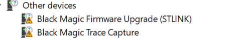
                                    The 2 new COM ports appear (COM12,COM13), but i cant seem to flash anything successfully.
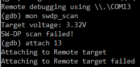
                                    I've installed the GNU arm toolchain for windows and tried "target extended-remote \.\COM13" (12 just gets stuck on nothing), and i get:
                                    f2dd9bb6-d333-41a8-b883-b3ba4a97d25f-image.png

                                    electrikE 1 Reply Last reply
                                    0
                                    • N Offline
                                      N Offline
                                      novicit
                                      wrote on last edited by
                                      #59

                                      @idanronen , I am not an expert but did manage to accomplish what you are doing about a year ago. I can tell you that you are supposed to get two com ports from BMP. Also, where your screen shot says "SW-DP scan failed" means BMP cannot find any 'targets' on the nrf52. You should get back something that looks like this from the scan:
                                      Available Targets:
                                      No. Att Driver
                                      1 ARM Cortex-M
                                      2 Nordic nRF52 Access Port

                                      I performed this operation on ~10 nrf52832 and only one failed the scan. I never found out how to solve it.

                                      Also, your use of the attach command is incorrect. You appear to be trying to attach the com port 13. If the swdp_scan had worked corrrectly, you would then attach the target that shows up in the scan. In my example output, it would be "attach 2" - the nRF52 Access Port.

                                      That adds what I know, hope it helps a bit.

                                      1 Reply Last reply
                                      0
                                      • electrikE Offline
                                        electrikE Offline
                                        electrik
                                        wrote on last edited by
                                        #60

                                        Hello, I'm using MySensors for some years now and after using the NRF24 and recently the RFM69 I want to explore the NRF5 platform.
                                        My idea is to use a NRF52840 as gateway, and NRF52832 as nodes. So I am making a list so I can get started, but was wondering what else I should order besides the NRF5's?
                                        I read a programmer is required, for example. What is your experience or advice for this? A ST-link or J-link? Could you share your experiences?
                                        Thanks
                                        Rik

                                        N 1 Reply Last reply
                                        0
                                        • electrikE electrik

                                          Hello, I'm using MySensors for some years now and after using the NRF24 and recently the RFM69 I want to explore the NRF5 platform.
                                          My idea is to use a NRF52840 as gateway, and NRF52832 as nodes. So I am making a list so I can get started, but was wondering what else I should order besides the NRF5's?
                                          I read a programmer is required, for example. What is your experience or advice for this? A ST-link or J-link? Could you share your experiences?
                                          Thanks
                                          Rik

                                          N Offline
                                          N Offline
                                          ncollins
                                          wrote on last edited by
                                          #61

                                          @electrik I believe NRF52832 and 51822 are the only supported NRF modules at this time. Some people have experimented and modified dependent libraries to get NRF52840 to work with MySensors but I'm not sure it's completely working and definitely wouldn't start there.

                                          Personally, I like using the Ebyte NRF24 PA+LNA modules for my gateways and repeaters and use the NRF5 modules for end nodes.

                                          I'm not even sure you can use NRF5 as a radio for a gateway, if so it might only work as a serial gateway.

                                          As for additional items, I bought a jlink clone after having trouble unlocking ebyte modules with a STLink. Then my jlink clone caused issues (old firmware, not updatable) so I ended up buying a real JLink-edu.

                                          Other things worth noting: there are a surprising number of hardware bugs with the NRF chips that mostly result in higher power consumption. General advice would be to stay away from NRF51822. EBYTE modules have been consistently reliable, high quality.

                                          Puneit ThukralP 1 Reply Last reply
                                          1
                                          Reply
                                          • Reply as topic
                                          Log in to reply
                                          • Oldest to Newest
                                          • Newest to Oldest
                                          • Most Votes


                                          10

                                          Online

                                          11.7k

                                          Users

                                          11.2k

                                          Topics

                                          113.0k

                                          Posts


                                          Copyright 2019 TBD   |   Forum Guidelines   |   Privacy Policy   |   Terms of Service
                                          • Login

                                          • Don't have an account? Register

                                          • Login or register to search.
                                          • First post
                                            Last post
                                          0
                                          • MySensors
                                          • OpenHardware.io
                                          • Categories
                                          • Recent
                                          • Tags
                                          • Popular