Step-up / Boost regulator PCBs
-
So, I've been looking into Eagle and making PCBs for various step-up regulators. This is the progress I've made so far. A panelized 5x5cm board with a couple of different designs for three different ICs (Linear LTC3525, Texas Instruments TPS61097, Texas Instruments TPS61221).
The panelizing / tabs and mouse bites were done using the Gerber Panelizer from This Is Not Rocket Science: http://blog.thisisnotrocketscience.nl/projects/pcb-design-tools/
The tool isn't public yet though. So if you want to test the alpha/beta you have to contact them through twitter ask for a copy. Props to Stijn Kuipers for taking the time to explain things to me. Bottom line: Gerbers are trickier than one might suspect at first glance.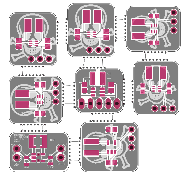
The TPS61097 is perhaps not the best IC around but I have a few samples so I thought I'd make use of them. Can't find that chip cheaply on AliExpress either and other sites (was it Lowpowerlabs?) have long since abandoned the TPS61097 due to some issue or another. So, off to smaller footprints. The TPS61221 which was talked about for the official MySensors battery board (TPS61222 was it?) is SC-70-6 unfortunately but CAN be found for about $1 a piece on AliExpress. A pretty good deal. But for now I have some samples I got from TI. Finally, the LTC3525, favored by a lot of hardware tinkerers, is a tad more expensive, around $2.3 on AliExpress. They all require the same number of external components and can work with the pretty much the same values (2x10uF or 1x10uF/1x1uF, 1x10uH) afaik.Sent the gerbers to DirtyPCBs yesterday, have been updating the order about six times by now ;-) Hopefully it will get processed before the Chinese New Year.
Since I have the PCBs that Meanpenguin designed I figured I'd make the first booster PCBs fit the AMS1117 pins so it will hang over the main PCB in an unobtrusive manner.
And yes, among other iffy things, the footprint for the inductor varies (a lot). I went with a couple of different footprints that I though would be hand solderable for a typical 3x3mm inductor (i..e with some of the pad exposed). In reality the inductor I ordered for testing has a horseshoe-like footprint similar to the PCB on the bottom left. The capacitor footprint also purposely differ (0603 and 0805), but the capacitors I have ordered are all 0603 so it is hopefully all good. This is my first real run with Eagle (and the Gerber Panelizer) so it has been a real learning experience for me. I hope that I will be able to reflow PCBs in the future and not have to worry about whether or not the tip of the soldering iron has anywhere to go.
Btw. Other components ordered:
- 10x Linear LTC3525DESC6-3.3
- 100x Capacitor KEMET C0603C105K9PACTU CAP CER 1UF 6.3V 10% X5R 0603
- 200x Capacitor TDK C1608X5R1A106K X5R 10uF 10V 10% 0603
- 50x Do3314-103mlc Inductor 3x3mm 10uH
We'll see if AliExpress delivers as promised. The components have all been dispatched at any rate. Prices were pretty good overall, particularly given that I save shipping and taxes compared to Mouser or whatever. First time I order "serious" brand components from Ali though. Fingers crossed!
I'm hoping that in the future we'll have ready booster PCBs on the official MySensors PCB site for all major ICs obviously. Personally I find the lack of proper low quiescent current regulators to be perhaps the most annoying problem right now.
-
Looking forward to the results..
-
Yeah looks good...im only just getting to the point where i want some good stable 3.3 regs...so will be very interested in the outcome! Nice work!
-
So, I've been looking into Eagle and making PCBs for various step-up regulators. This is the progress I've made so far. A panelized 5x5cm board with a couple of different designs for three different ICs (Linear LTC3525, Texas Instruments TPS61097, Texas Instruments TPS61221).
The panelizing / tabs and mouse bites were done using the Gerber Panelizer from This Is Not Rocket Science: http://blog.thisisnotrocketscience.nl/projects/pcb-design-tools/
The tool isn't public yet though. So if you want to test the alpha/beta you have to contact them through twitter ask for a copy. Props to Stijn Kuipers for taking the time to explain things to me. Bottom line: Gerbers are trickier than one might suspect at first glance.
The TPS61097 is perhaps not the best IC around but I have a few samples so I thought I'd make use of them. Can't find that chip cheaply on AliExpress either and other sites (was it Lowpowerlabs?) have long since abandoned the TPS61097 due to some issue or another. So, off to smaller footprints. The TPS61221 which was talked about for the official MySensors battery board (TPS61222 was it?) is SC-70-6 unfortunately but CAN be found for about $1 a piece on AliExpress. A pretty good deal. But for now I have some samples I got from TI. Finally, the LTC3525, favored by a lot of hardware tinkerers, is a tad more expensive, around $2.3 on AliExpress. They all require the same number of external components and can work with the pretty much the same values (2x10uF or 1x10uF/1x1uF, 1x10uH) afaik.Sent the gerbers to DirtyPCBs yesterday, have been updating the order about six times by now ;-) Hopefully it will get processed before the Chinese New Year.
Since I have the PCBs that Meanpenguin designed I figured I'd make the first booster PCBs fit the AMS1117 pins so it will hang over the main PCB in an unobtrusive manner.
And yes, among other iffy things, the footprint for the inductor varies (a lot). I went with a couple of different footprints that I though would be hand solderable for a typical 3x3mm inductor (i..e with some of the pad exposed). In reality the inductor I ordered for testing has a horseshoe-like footprint similar to the PCB on the bottom left. The capacitor footprint also purposely differ (0603 and 0805), but the capacitors I have ordered are all 0603 so it is hopefully all good. This is my first real run with Eagle (and the Gerber Panelizer) so it has been a real learning experience for me. I hope that I will be able to reflow PCBs in the future and not have to worry about whether or not the tip of the soldering iron has anywhere to go.
Btw. Other components ordered:
- 10x Linear LTC3525DESC6-3.3
- 100x Capacitor KEMET C0603C105K9PACTU CAP CER 1UF 6.3V 10% X5R 0603
- 200x Capacitor TDK C1608X5R1A106K X5R 10uF 10V 10% 0603
- 50x Do3314-103mlc Inductor 3x3mm 10uH
We'll see if AliExpress delivers as promised. The components have all been dispatched at any rate. Prices were pretty good overall, particularly given that I save shipping and taxes compared to Mouser or whatever. First time I order "serious" brand components from Ali though. Fingers crossed!
I'm hoping that in the future we'll have ready booster PCBs on the official MySensors PCB site for all major ICs obviously. Personally I find the lack of proper low quiescent current regulators to be perhaps the most annoying problem right now.
@bjornhallberg it is very good job and very nive "killing" design!)
will be looking forward for your progress.,
I did a similar thing with TPS61221 and MCP1640 http://forum.mysensors.org/topic/197/mysensors-micro-step-up-module-revision-1-0
but get stacked with my load testing.,
I was failed to get more than 10mA 3.3V output while having 1.5V input
with 1.8V input all is OKhave tested different inductors and capacitors but something went wrong
-
@bjornhallberg it is very good job and very nive "killing" design!)
will be looking forward for your progress.,
I did a similar thing with TPS61221 and MCP1640 http://forum.mysensors.org/topic/197/mysensors-micro-step-up-module-revision-1-0
but get stacked with my load testing.,
I was failed to get more than 10mA 3.3V output while having 1.5V input
with 1.8V input all is OKhave tested different inductors and capacitors but something went wrong
@axillent Dang. That is some sad news indeed. Particularly since I found a cheap supply of TPS61221 and thought it could the solutions to all my problem :tired_face:
Does that mean we wont be seeing an official boost module?
Btw. Do you mean TPS61221 or TPS61220? You were making a variable 5V/3.3V module as well?
-
@axillent Dang. That is some sad news indeed. Particularly since I found a cheap supply of TPS61221 and thought it could the solutions to all my problem :tired_face:
Does that mean we wont be seeing an official boost module?
Btw. Do you mean TPS61221 or TPS61220? You were making a variable 5V/3.3V module as well?
@bjornhallberg your version is cool to be an official one))
I hope you will succeed with your design but pay attention to the testing. With such things as high frequency switching DC-DC all is important - coper design, selection of capacitors and inductors. By the datasheet TPS61221/TPS61220 should provide a sufficient current on the output
-
So, still waiting for some of the components. Got some samples from Linear (3V, 3.3V and 5V versions of the LTC3525). PCBs have been manufactured and posted a couple of days ago. No complaints from the PCB house at least.
Got the 1uF capacitors and inductors though. 1206 capacitor for reference:
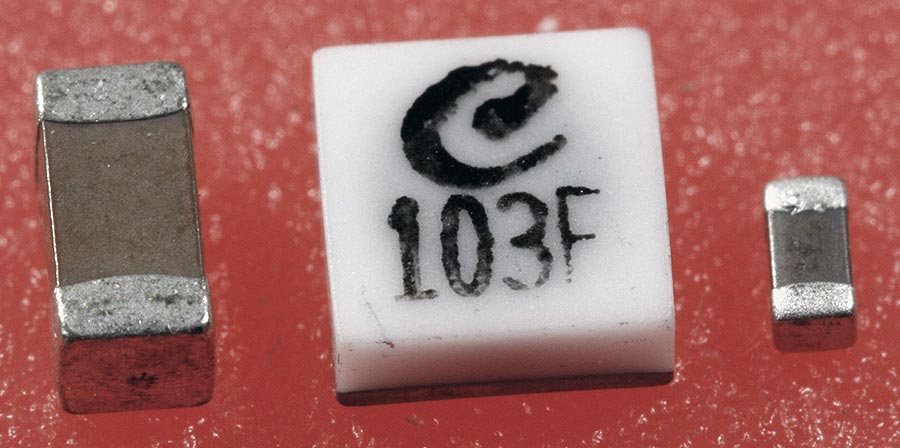
That is one adorable inductor. Lets hope it works too.
Shipping from China remains as unpredictable as ever.
-
The dirty boards have arrived! Unfortunately I am still missing 10uF in 0603 and haven't had time to test the boards yet.
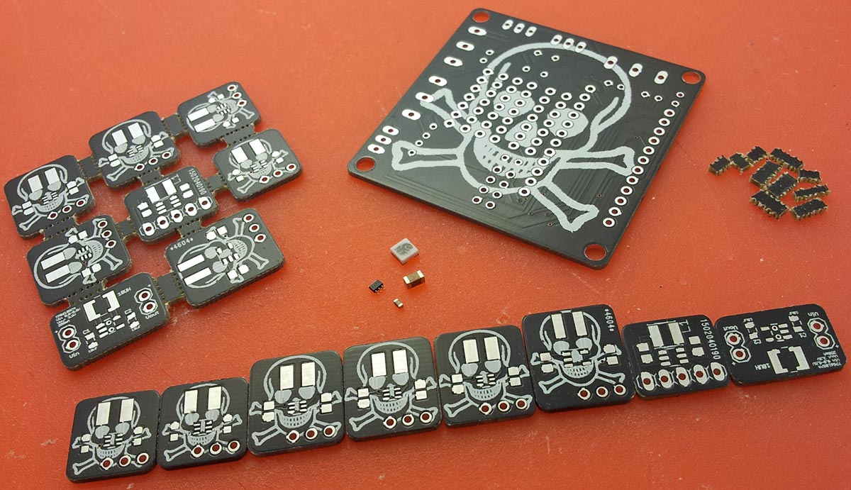
Some observations: Precision seems a bit off, but I doubt it will matter. Not that I'd expect better from any of the cheap PCB houses. And yes, I managed to miss the silkscreen again on some of the boards. I also used far too many tabs between the boards. Smaller tabs, fewer tabs, and a slightly thinner PCB (1mm next time?) would have been faster to depanelize. Finally, the endless debate over the size of solder pads. I mean, the SC70-6 pads I put in are just silly to hand solder. The ones on the center board (not my design) are hilariously oversized and an SC70-6 component will almost fall between the pads. But I guess it is all part of the learning experience.
I really should get a reflow oven.
-
The dirty boards have arrived! Unfortunately I am still missing 10uF in 0603 and haven't had time to test the boards yet.
Some observations: Precision seems a bit off, but I doubt it will matter. Not that I'd expect better from any of the cheap PCB houses. And yes, I managed to miss the silkscreen again on some of the boards. I also used far too many tabs between the boards. Smaller tabs, fewer tabs, and a slightly thinner PCB (1mm next time?) would have been faster to depanelize. Finally, the endless debate over the size of solder pads. I mean, the SC70-6 pads I put in are just silly to hand solder. The ones on the center board (not my design) are hilariously oversized and an SC70-6 component will almost fall between the pads. But I guess it is all part of the learning experience.
I really should get a reflow oven.
@bjornhallberg I'm trying to make some boards with the panelizer as well but I can't get the slots in the middle to show up in most gerber viewers. Did you have this problem? If so, how did you resolve it?
Example:
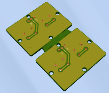
The slots ARE in the .gko file but won't show up.
-
@bjornhallberg I'm trying to make some boards with the panelizer as well but I can't get the slots in the middle to show up in most gerber viewers. Did you have this problem? If so, how did you resolve it?
Example:
The slots ARE in the .gko file but won't show up.
@slarti Yes, that happened to me as well. My guess would be that you have your outline layer in just about every gerber. Some board houses (like DirtyPCBs) like it that way or have it in their CAM anyway. The panelizer however only works if you include the outline layer ONLY in your .GKO.
If you send the files as shown above, your board house will probably figure things out, but then again they may not.
-
@slarti Yes, that happened to me as well. My guess would be that you have your outline layer in just about every gerber. Some board houses (like DirtyPCBs) like it that way or have it in their CAM anyway. The panelizer however only works if you include the outline layer ONLY in your .GKO.
If you send the files as shown above, your board house will probably figure things out, but then again they may not.
@bjornhallberg No, I only have the outline in the .gko file. It shows up fine in the picture generated by the panelizer but not in (almost) any viewer I've tried. Well, I sent the files in already so I guess we'll see what happens... :wink:
-
Oh, yeah. Did you get a .gml file (milling)? If I included one of those every viewer went nuts and DirtyPCB wouldn't accept the file. When I left it out, everything was fine except for the problem described above.
@slarti I see now that at least GRBV doesn't render the output gerbers correctly. Weird. Oh well, mine worked fine and so will yours probably.
I think I deleted the .GML. I also recall some sort of error if I didn't. "Board outline not found in GML/GBR/GKO file" or some such.
-
@slarti I see now that at least GRBV doesn't render the output gerbers correctly. Weird. Oh well, mine worked fine and so will yours probably.
I think I deleted the .GML. I also recall some sort of error if I didn't. "Board outline not found in GML/GBR/GKO file" or some such.
@bjornhallberg Good to know, thanks! Seems we had the same problems.
-
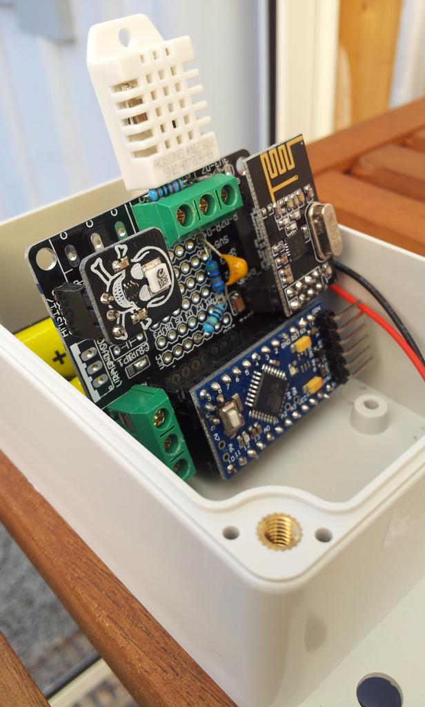
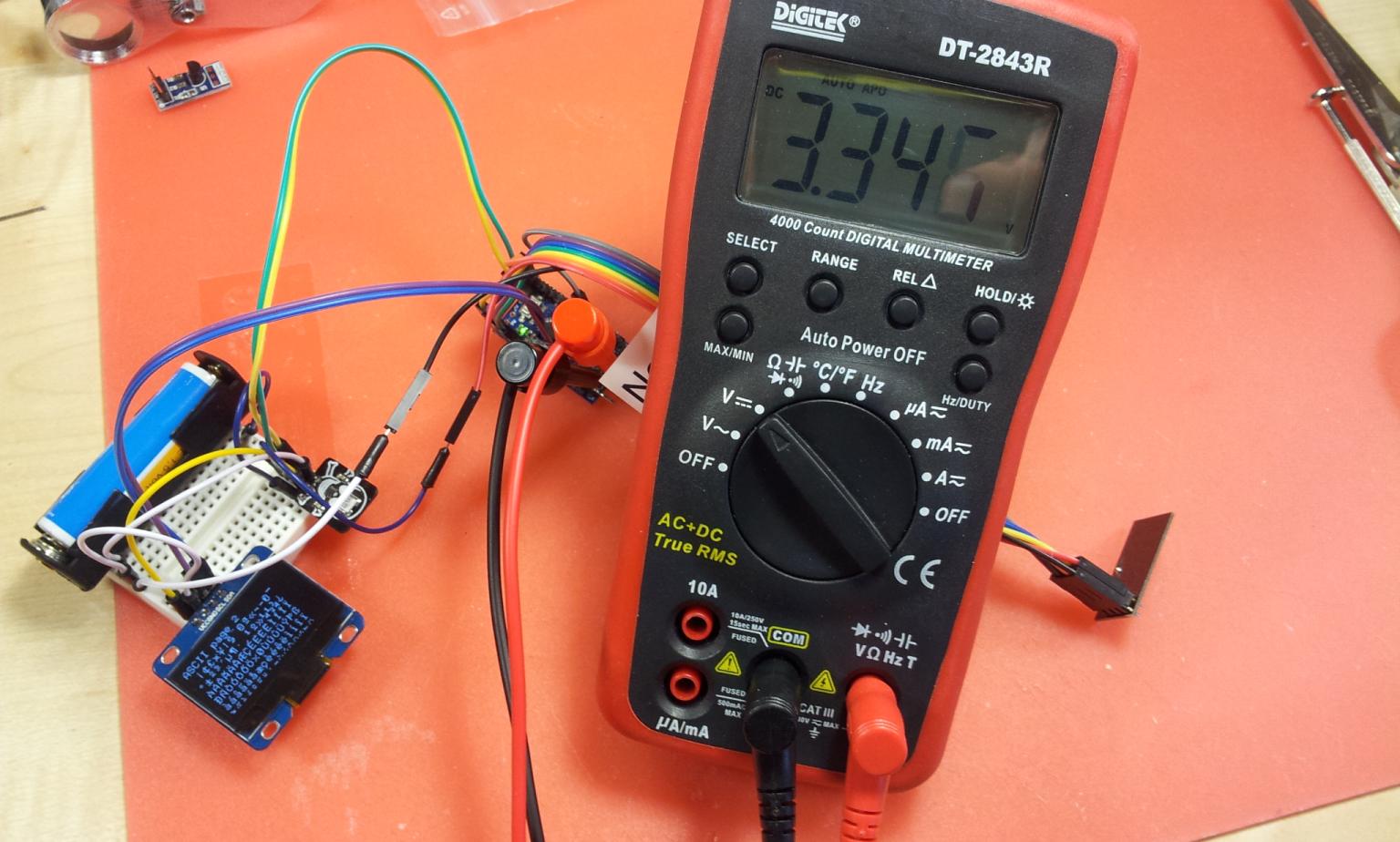
So, in conclusion I assembled the boost modules. I don't have an oscilloscope or any fancy variable load so I can't do much testing. But both the TPS61221 and LTC3525 seem to be working as intended, they power the NRF24 (not sensor in this particular picture below) without any hiccups at any rate.
I tried some ceramic power resistors to put some load on the regulators and got something like ~60-80mA out of one fairly run down AA cell if I'm not mistaken. Basically according to spec.
All I have to do now is design a compact sensor node where 1xAA actually makes sense. Kind of like LowPowerLabs' Moteino. Feels like it's time to take this to the next level. The only thing bugging me is the need to reflow instead of hand solder, and the massive task of sourcing components from AliExpress so I can avoid Mouse/Digikey. Perhaps I should give it a rest for now and see how the official MySensors modules turn out before I decide.
-
Powering a 1.3 inch OLED display (i2c).
Now if I could only put all of this together as a scene controller or whatever in a nice 3d printed box. -
bjornhallberg, this is an excellent project. I’ve noticed that you ordered your components from AliExpress instead of mouse, farnell or digikey. I mostly order my components from farnell or digikey since mouse is a bit expensive. AliExpress is cheaper than all of these by a mile and I have been thinking of ordering from their stores but I can’t risk placing an order and not having my components delivered or not having the components that I ordered delivered. Please let me know how you found their service. Congratulations on a successful project by the way.
-
bjornhallberg, this is an excellent project. I’ve noticed that you ordered your components from AliExpress instead of mouse, farnell or digikey. I mostly order my components from farnell or digikey since mouse is a bit expensive. AliExpress is cheaper than all of these by a mile and I have been thinking of ordering from their stores but I can’t risk placing an order and not having my components delivered or not having the components that I ordered delivered. Please let me know how you found their service. Congratulations on a successful project by the way.
@pedrodova I think AliExpress has worked out nicely so far, though I can't be 100% sure I'm not getting counterfeit components from time to time (hard to tell with capacitors). Though it would seem unlikely with the rather uncommon components here, I mean if someone were putting out fake ICs they'd be all over Ebay/Ali and they're not obviously. There are only a few people selling LTC3525 and only one guy selling the inductor on Ali for instance, and prices are usually on par with Digikey etc if you look at volume sales and disregard shipping/customs. Considering the whole debacle with the NRF24 radio though I'll certainly be vigilant in the future in case things change.
I have ordered perhaps ~250 items from Ebay and ~25 from Ali and only ever had two things disappear in shipping (both from Ebay and one quite recently). Never had an issue with a seller not issuing a refund or re-sending a broken item. AliExpress packages are almost always sent as registered mail (as opposed to most Ebay packages) so I'll end up having to pick them up at my local post office as opposed to just being shoved in my mailbox. Shipping to Sweden takes about a month most of the time and some sellers are pretty slow to ship (though it is always stated on their item pages). If someone claims to take 15-20 days to even ship, you better believe it. Still haven't figured out why package delivery times differ so much either. Like I said, a month is what to expect but I've literally had packages (mostly from Ebay) arrive within a week.
Biggest issue with AliExpress is perhaps their search engine and the way some sellers list their items. Trying to find what you're looking for (or alternative products) can seem impossible sometimes.
Overall I'd say AliExpress is pretty safe and a nice way to save a few bucks on components - if you can find them, wont mind waiting and don't have a ton of components on your shopping list.
-
I hope you will succeed with your design but pay attention to the testing. With such things as high frequency switching DC-DC all is important - coper design, selection of capacitors and inductors.
Hello! It looks like you're interested in this conversation, but you don't have an account yet.
Getting fed up of having to scroll through the same posts each visit? When you register for an account, you'll always come back to exactly where you were before, and choose to be notified of new replies (either via email, or push notification). You'll also be able to save bookmarks and upvote posts to show your appreciation to other community members.
With your input, this post could be even better 💗
Register Login