RGBW controller design issues

-
Hello all,
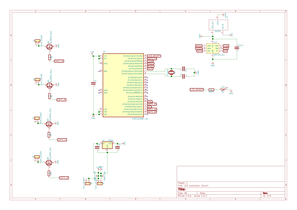
I hope you could help me with something. I am currently working on troubleshooting my own RGBW LED controller. I have made the PCB's myself but after uploading the software there is no response from the controller. I am using a SMD NRF24L01 + PA + LNA board and I have made the pinout accordingly. Unfortunately I can not for the life of me find the (electrical) issue with my design. I did check everything with a multimeter and find all connections as should be. Am I missing some critical component which you should include with the atmega328p smd chip? I do have the atmega328 p pu-ph chip by the way but I am able to read and write on it so that should not be an issue (I hope).
I hope that you guys can be of assistance.
Thanks in advance!
Kind regards,
Jim! -
Hello all,
I hope you could help me with something. I am currently working on troubleshooting my own RGBW LED controller. I have made the PCB's myself but after uploading the software there is no response from the controller. I am using a SMD NRF24L01 + PA + LNA board and I have made the pinout accordingly. Unfortunately I can not for the life of me find the (electrical) issue with my design. I did check everything with a multimeter and find all connections as should be. Am I missing some critical component which you should include with the atmega328p smd chip? I do have the atmega328 p pu-ph chip by the way but I am able to read and write on it so that should not be an issue (I hope).
I hope that you guys can be of assistance.
Thanks in advance!
Kind regards,
Jim!@jim-de-groot You have no pullup on the PC6/RESET have you disabled RESET with the fuse settings?
-
@hard-shovel That is probably going to be my problem.. I will try it this afternoon! thank you very much for your help! I have been staring blind on the issue! If I am going to disable the pin in fuses is the chip still programmable? That because I thought that the reset pin needs to be pulled low before starting programming to get the chip in a halt state?
@jim-de-groot I have not tried reprograming with the reset disabled. Maybe with power on reset and then program. Otherwise a high voltage programmer will be required.
On your schematic i do not see any programing pins (ie ICSP connector) are you using pogo pins or some other connector to upload?
I am also confused as you say you have a atmega328 p pu-ph chip (DIP) and the schematic shows a atmega328P-AU (SMD). The pin numbering of the two chips is different.
-
@jim-de-groot I have not tried reprograming with the reset disabled. Maybe with power on reset and then program. Otherwise a high voltage programmer will be required.
On your schematic i do not see any programing pins (ie ICSP connector) are you using pogo pins or some other connector to upload?
I am also confused as you say you have a atmega328 p pu-ph chip (DIP) and the schematic shows a atmega328P-AU (SMD). The pin numbering of the two chips is different.
@hard-shovel
The chip is this type
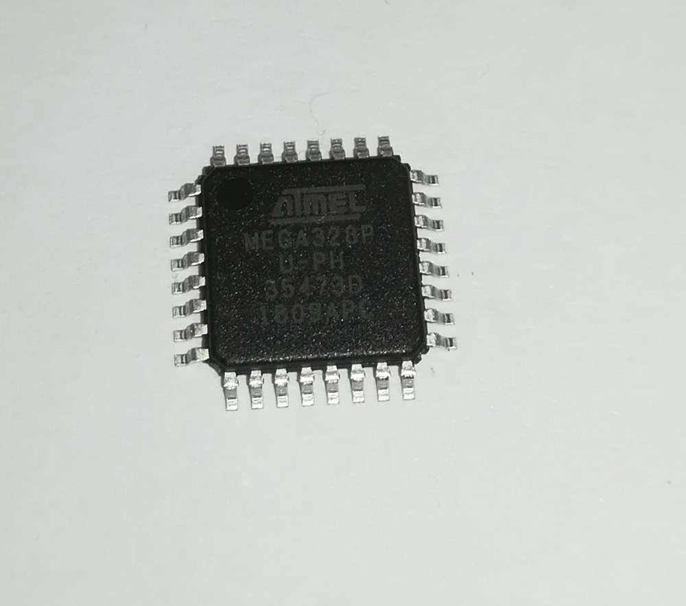
I am externally programming it and then soldering it on the board. I did try to use a 10K resistor between reset and 5VDC source, it did not work unfortunately. Do I also need to use a 0.1 uf decoupling capacitor with it as well? I am afraid that I maybe fried the chip in the meantime... Also I am not very certain about the NRF24L01 + PA + LNA SMD antenna. I think I am going back to the drawing board and design it for an non-SMD antenna.
Thanks,
Jim -
@hard-shovel
The chip is this type
I am externally programming it and then soldering it on the board. I did try to use a 10K resistor between reset and 5VDC source, it did not work unfortunately. Do I also need to use a 0.1 uf decoupling capacitor with it as well? I am afraid that I maybe fried the chip in the meantime... Also I am not very certain about the NRF24L01 + PA + LNA SMD antenna. I think I am going back to the drawing board and design it for an non-SMD antenna.
Thanks,
Jim@jim-de-groot
Have you actually tested your code prior to making the board?Decoupling capacitor to the reset line helps with noise. I also would add connections or pads for ICSP so the chip can be reprogrammed, it also be nice to have the serial line pads available as well.
I guessing you were trying to make this board as small as possiblei also think you need to redo the 3.3V regulator as the supply to the NRF24L01 has to be perfect and you do not show any input or output capacitors for the regulator only the smoothing capacitor for the radio.
-
Hmm, how did You program this board ? :) There is no ISP header. And also no UART header - this is must have, without it You will not be able to see the debug logs form the node and those are VERY helpful. There is also missing some decoupling capacitors around atmega. All VCC pins must have 100nF decoupling capacitor as close as possible - all digital ICs require that.
-
Thanks all for your input. It is going to be back to the drawing board for me. At least I learned a lot about the mistakes made here. I did try the setup on a breadboard before and that worked but that was with a arduino pro mini so not with the seperate chip. Aw well lessons learned and let's get going for the next PCB. Probably gonna post it here before ordering it :wink:
Hello! It looks like you're interested in this conversation, but you don't have an account yet.
Getting fed up of having to scroll through the same posts each visit? When you register for an account, you'll always come back to exactly where you were before, and choose to be notified of new replies (either via email, or push notification). You'll also be able to save bookmarks and upvote posts to show your appreciation to other community members.
With your input, this post could be even better 💗
Register Login