[SOLVED] Gateway RS485
-
Hello
I created a gateway RS485, I inject a comunication test sketch and it works without problem. when I inject the sketch mysensors 2.3.0 RS485 with the examples that are on the site it does not work, the node sends many infos on the RS485 but the gateway does not respond, while in the debug of the gateway does not mark no mistake and send well from time to time frames.
if you need more info I will put my codes
thank you for your help because it's been more days that I tear my hair lol
-
Hello and thank you for answering me, here are the log:
Debug Gateway :
0;255;3;0;9;0 MCO:BGN:INIT GW,CP=RSNGA---,VER=2.3.0
0;255;3;0;9;4 TSM:INIT
0;255;3;0;9;6 TSF:WUR:MS=0
0;255;3;0;9;9 TSM:INIT:TSP OK
0;255;3;0;9;11 TSM:INIT:GW MODE
0;255;3;0;9;14 TSM:READY:ID=0,PAR=0,DIS=0
0;255;3;0;9;18 MCO:REG:NOT NEEDED
0;255;3;0;14;Gateway startup complete.
0;255;0;0;18;2.3.0
0;255;3;0;9;22 MCO:BGN:STP
0;255;3;0;9;28 MCO:BGN:INIT OK,TSP=1
Debug Node :
 __  __       ____
|  \/  |_   _/ ___|  ___ _ __  ___  ___  _ __ ___
| |\/| | | | \___ \ / _ \ `_ \/ __|/ _ \| `__/ __|
| |  | | |_| |___| |  __/ | | \__ \  _  | |  \__ \
|_|  |_|\__, |____/ \___|_| |_|___/\___/|_|  |___/
        |___/                      2.3.0

16 MCO:BGN:INIT NODE,CP=RSNNA---,VER=2.3.0
25 TSM:INIT
26 TSF:WUR:MS=0
28 TSM:INIT:TSP OK
29 TSM:INIT:STATID=6
31 TSF:SID:OK,ID=6
33 TSM:FPAR
34 TSM:FPAR:STATP=0
36 TSM:ID
37 TSM:ID:OK
38 TSM:UPL
57 TSF:MSG:SEND,6-6-0-0,s=255,c=3,t=24,pt=1,l=1,sg=0,ft=0,st=OK:1
2064 TSM:UPL
2082 TSF:MSG:SEND,6-6-0-0,s=255,c=3,t=24,pt=1,l=1,sg=0,ft=0,st=OK:1
4089 TSM:UPL
4108 TSF:MSG:SEND,6-6-0-0,s=255,c=3,t=24,pt=1,l=1,sg=0,ft=0,st=OK:1
6115 TSM:UPL
6133 TSF:MSG:SEND,6-6-0-0,s=255,c=3,t=24,pt=1,l=1,sg=0,ft=0,st=OK:1
8140 !TSM:UPL:FAIL
8141 TSM:FPAR
8143 TSM:FPAR:STATP=0
8145 TSM:ID
8146 TSM:ID:OK
8147 TSM:UPL
8167 TSF:MSG:SEND,6-6-0-0,s=255,c=3,t=24,pt=1,l=1,sg=0,ft=0,st=OK:1
10174 TSM:UPL
10192 TSF:MSG:SEND,6-6-0-0,s=255,c=3,t=24,pt=1,l=1,sg=0,ft=0,st=OK:1
12200 TSM:UPL
12219 TSF:MSG:SEND,6-6-0-0,s=255,c=3,t=24,pt=1,l=1,sg=0,ft=0,st=OK:1
14226 TSM:UPL
14244 TSF:MSG:SEND,6-6-0-0,s=255,c=3,t=24,pt=1,l=1,sg=0,ft=0,st=OK:1
16252 !TSM:UPL:FAIL
16253 TSM:FPAR
16256 TSM:FPAR:STATP=0
16258 TSM:ID
16259 TSM:ID:OK
16261 TSM:UPL
the sketch are the default ones for the RS485
Thank you for your help
-
Thanks. I put the node log into the log parser to make it easier to read.
Looks like the messages don't reach the gateway (since the gateway does not log the messages sent by the node).
I don't have any experience with rs485 but hopefully someone else has an idea. -
I try with another sketch for rs485 and my two arduino comunique well together with the same hardware configuration.
did I notice the node sends many infos on the RS485 network (tested with a sketch snifer RS485) but the gateway send anything on the RS485 network
if someone has already done mysensors on the RS485 thank you for sharing your skit to find what is wrong
-
@philippe-57 said in Gateway RS485:
Try connect gateway and node without 485 transmitters - only crosswire TX and RX pins
with the same sketch. It will eliminate possible problems with DE pins . -
after testing by putting the serial connections live (and well reversed the TX and RX) there is no communication between the node and the gateway while with my test sketch that function, CAUTION: I do not use the same library as mysensors:
on mysensors we use : AltSoftSerial
on my test sketch I use : SoftwareSerialno need to put the debug because it's the same as above
-
here is my test sketch:
Master :
#include <SoftwareSerial.h>

int MAX485_Receiver_Output_PIN = 8;
int MAX485_Driver_Input_PIN = 9;
int MAX485_Driver_Output_Enable_PIN = 2;

int debug_led = 13;

SoftwareSerial software_serial (MAX485_Receiver_Output_PIN, MAX485_Driver_Input_PIN); // RX, TX

void setup()
{
  Serial.begin(115200); // begin hardware serial
  software_serial.begin(9600); // begin software serial

  pinMode(MAX485_Driver_Output_Enable_PIN, OUTPUT);
  digitalWrite(MAX485_Driver_Output_Enable_PIN, HIGH); // this disables Receiver Output Enable and enables Driver Output Enable
}

void loop()
{
   byte to_send = 0; // declare the byte to be sent to the slaves though, init as 0
  int rate;

  while (true)
  {
    // invert the byte to be sent
    if (to_send == 1) to_send = 0;
    else if (to_send == 0) to_send = 1;

    Serial.print("Sending: ");
    Serial.println(to_send);

    digitalWrite(debug_led, to_send);

    rate = map(analogRead(5), 0, 1023, 0, 1000);

    software_serial.write(to_send); // send our byte out to the MAX485

    delay(rate);
  }
}
Slave :
#include <SoftwareSerial.h>

int MAX485_Receiver_Output_PIN = 8;
int MAX485_Driver_Input_PIN = 9;
int MAX485_Driver_Output_Enable_PIN = 2;

int debug_led_PIN = 13;

SoftwareSerial software_serial (MAX485_Receiver_Output_PIN, MAX485_Driver_Input_PIN); // RX, TX

void setup()
{

  Serial.begin(115200); // begin hardware serial
  software_serial.begin(9600); // begin software serial

  pinMode(MAX485_Driver_Output_Enable_PIN, OUTPUT);
  digitalWrite(MAX485_Driver_Output_Enable_PIN, LOW);

  pinMode(debug_led_PIN, OUTPUT);

}

void loop() // run over and over
{
  byte k;

  if (software_serial.available() > 0) // make sure there is something to read
  {
    k = software_serial.read();// read in a single byte from the serial port
    Serial.println(k);
    digitalWrite(debug_led_PIN, k);
  }
}
this skit makes it possible to blink the led 13 with a variation of the potentiometer which changes the delay of the blinking
-
I use for each pcb arduino nano:
-
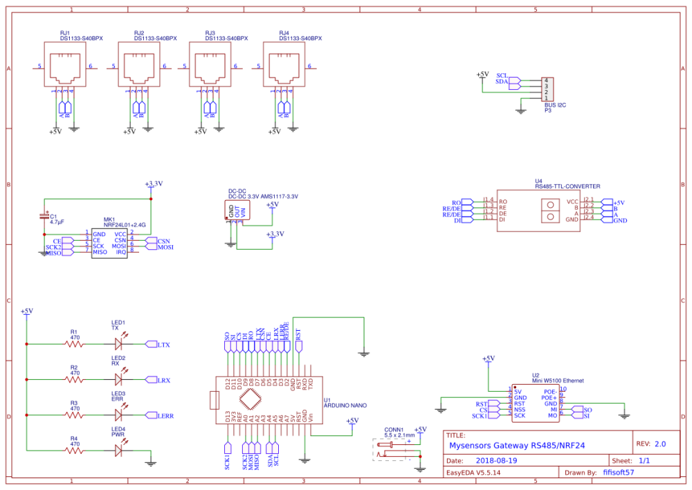
@philippe-57 I cannot see the schematic for the two boards so:
1 is the the Max485 RE and DE connections jumpered together at the PCB or on the module? without this jumper you will have no communication.
2 Do the RJ45s have A, B and a common?
3 The gateway board has the footprint for the W5100 ethernet module, but the log file does not list an ip address like the ver 2.3.1 below, are you using a serial gateway?0 MCO:BGN:INIT GW,CP=RSNGA---,VER=2.3.1-alpha 4 TSM:INIT 4 TSF:WUR:MS=0 6 TSM:INIT:TSP OK 7 TSM:INIT:GW MODE 9 TSM:READY:ID=0,PAR=0,DIS=0 12 MCO:REG:NOT NEEDED 314 GWT:TIN:IP=192.168.1.152 1316 MCO:BGN:STP 1318 MCO:BGN:INIT OK,TSP=1 1320 TSM:READY:NWD REQ 1347 TSF:MSG:SEND,0-0-255-255,s=255,c=3,t=20,pt=0,l=0,sg=0,ft=0,st=OK:The GatewaySerialRS485.ino sketch and the demo MotionSensorRS485/MotionSensorRS485.ino sketch do definitely work at least for a few hours that i tested today.
-
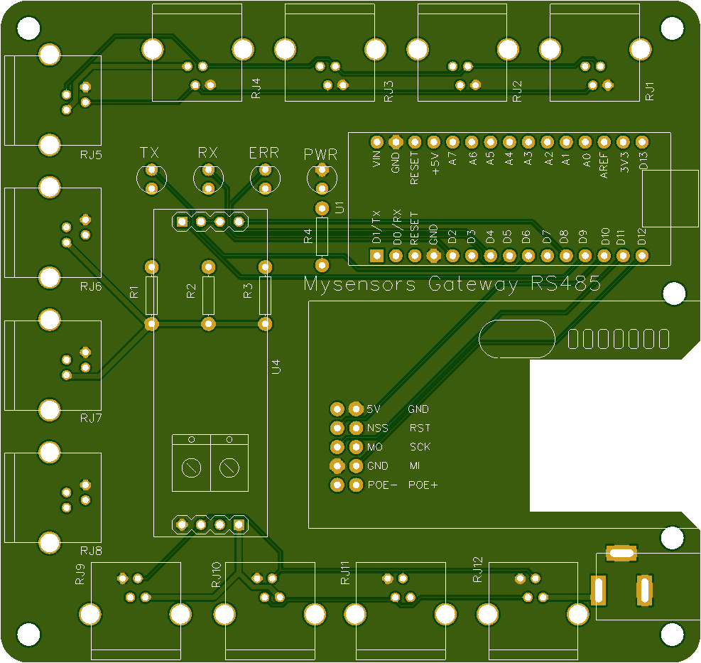
Hello
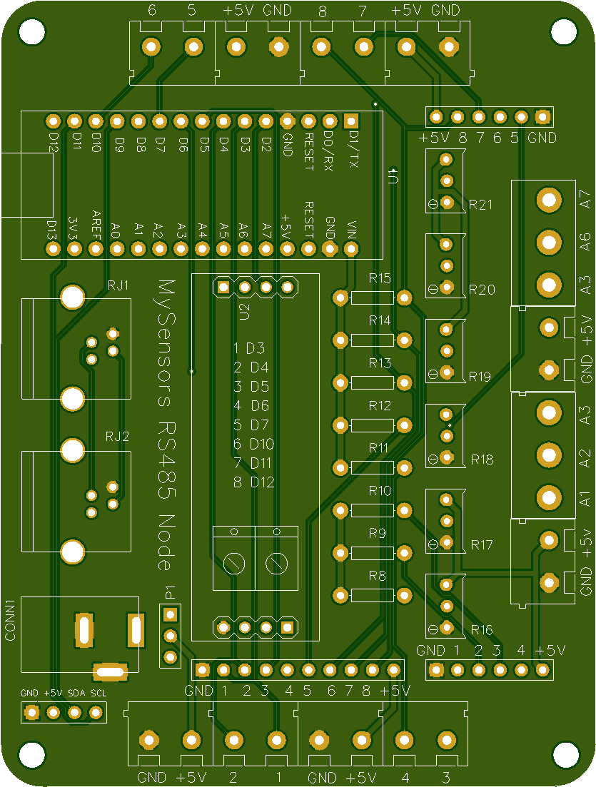
Here is the diagram of my card but since I made some modification I added a module NRF24 but not programmed and the W5100 is not present too, it is a universal turntable.
with my test skit no problem it works with the same component on the PCB the only thing weird is that the NODE sends much info on the RS485 but not the gateway
I will try to reverse the turntables and sketches to see if it is not an arduino problem or not
-
after inversion of the sketch the problem remains the same the NODE sends many infos on the network RS485 but the gateway receive nothing
since the gateway sends a frame from time to time I will wait to see if there is really anything on the RS485 network and if I receive info it means that my node and my gateway do not understand on the RS485 network
-
New PCB :
-
Hello
following tests:
debug gateway:
0;255;3;0;9;0 MCO:BGN:INIT GW,CP=RSNGA---,VER=2.3.0
0;255;3;0;9;4 TSM:INIT
0;255;3;0;9;6 TSF:WUR:MS=0
0;255;3;0;9;9 TSM:INIT:TSP OK
0;255;3;0;9;11 TSM:INIT:GW MODE
0;255;3;0;9;14 TSM:READY:ID=0,PAR=0,DIS=0
0;255;3;0;9;18 MCO:REG:NOT NEEDED
0;255;3;0;14;Gateway startup complete.
0;255;0;0;18;2.3.0
0;255;3;0;9;22 MCO:BGN:STP
0;255;3;0;9;28 MCO:BGN:INIT OK,TSP=1
0;255;3;0;9;900007 TSF:SAN:OK
0;255;3;0;9;1200001 TSM:READY:NWD REQ
0;255;3;0;9;1200020 TSF:MSG:SEND,0-0-255-255,s=255,c=3,t=20,pt=0,l=0,sg=0,ft=0,st=OK:
0;255;3;0;9;1800008 TSF:SAN:OK
0;255;3;0;9;2400002 TSM:READY:NWD REQ
0;255;3;0;9;2400021 TSF:MSG:SEND,0-0-255-255,s=255,c=3,t=20,pt=0,l=0,sg=0,ft=0,st=OK:
0;255;3;0;9;2700009 TSF:SAN:OK
0;255;3;0;9;5400032 TSF:SAN:OK
0;255;3;0;9;6000005 TSM:READY:NWD REQ
0;255;3;0;9;6000024 TSF:MSG:SEND,0-0-255-255,s=255,c=3,t=20,pt=0,l=0,sg=0,ft=0,st=OK:
0;255;3;0;9;6300033 TSF:SAN:OK
I found no trace on the RS485 network despite the frame sent by the gateway
I also reversed the code to do the other way and it's the same, the geteway sends the frame but nothing on the RS485
for the node I can see the frames on the RS485 that I'm on deck 1 or 2
so I guess it comes from the sketch of the gateway, after I do not know or look for debug
The gateway debug log looks ok to me as it is starting and then not getting any node data to process.
How are the boards connected together, are you using the RJ11 sockets, if so is the cable actually connected A-A B-B & Common?
Or are you using the screw terminals on the boards, if so do you also have a common connection between the two grounds?Have you tried the previous suggestion by "kimot" to connect the two boards together with the max485 removed,
Ie gateway Pin 8 to Node Pin 9, Gateway Pin 9 to Node Pin 8, and GND to GND on both boards.You may also want to try and fix the Node ID on the other board.
#define MY_NODE_ID 155 // setting a known ID may help with establishing communicationif you want to see more response from the gate when it working then could try to use ack.
// Change folllowing line
//send(msg.set(tripped?"1":"0"));  // Send tripped value to gw

  if (send(msg.set(tripped?"1":"0"),true)) {    // Send tripped value to gw and request ack
  Serial.println("Transmission Link Ok");
  } else {
    Serial.println("Message Fail");
  }
this will make the gateway send ack back to the node however:
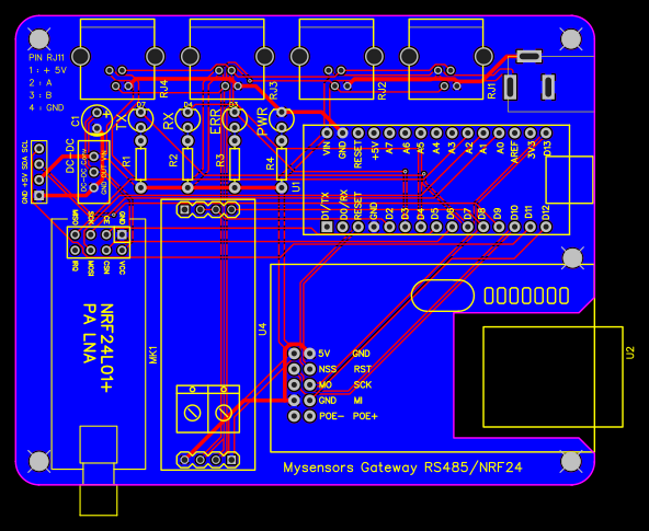
NOTE
The Node will always show OK even if there is no response from the gateway when using RS485 transport layer.On the updated board you have the +5V connected to the Vin on the Nano. Is this deliberate to use the Nano's regulator, rather than feed in to the 5V connection?
-
Hello
following tests:
debug gateway:
0;255;3;0;9;0 MCO:BGN:INIT GW,CP=RSNGA---,VER=2.3.0
0;255;3;0;9;4 TSM:INIT
0;255;3;0;9;6 TSF:WUR:MS=0
0;255;3;0;9;9 TSM:INIT:TSP OK
0;255;3;0;9;11 TSM:INIT:GW MODE
0;255;3;0;9;14 TSM:READY:ID=0,PAR=0,DIS=0
0;255;3;0;9;18 MCO:REG:NOT NEEDED
0;255;3;0;14;Gateway startup complete.
0;255;0;0;18;2.3.0
0;255;3;0;9;22 MCO:BGN:STP
0;255;3;0;9;28 MCO:BGN:INIT OK,TSP=1
0;255;3;0;9;900007 TSF:SAN:OK
0;255;3;0;9;1200001 TSM:READY:NWD REQ
0;255;3;0;9;1200020 TSF:MSG:SEND,0-0-255-255,s=255,c=3,t=20,pt=0,l=0,sg=0,ft=0,st=OK:
0;255;3;0;9;1800008 TSF:SAN:OK
0;255;3;0;9;2400002 TSM:READY:NWD REQ
0;255;3;0;9;2400021 TSF:MSG:SEND,0-0-255-255,s=255,c=3,t=20,pt=0,l=0,sg=0,ft=0,st=OK:
0;255;3;0;9;2700009 TSF:SAN:OK
0;255;3;0;9;5400032 TSF:SAN:OK
0;255;3;0;9;6000005 TSM:READY:NWD REQ
0;255;3;0;9;6000024 TSF:MSG:SEND,0-0-255-255,s=255,c=3,t=20,pt=0,l=0,sg=0,ft=0,st=OK:
0;255;3;0;9;6300033 TSF:SAN:OK
I found no trace on the RS485 network despite the frame sent by the gateway
I also reversed the code to do the other way and it's the same, the geteway sends the frame but nothing on the RS485
for the node I can see the frames on the RS485 that I'm on deck 1 or 2
so I guess it comes from the sketch of the gateway, after I do not know or look for debug
@philippe-57
If you have a spare board you could connect it to the rs485 bus and monitor the data traffic between the boards , or if no spares then check that the gateway or node is actually sending data.
Load the modified sketch biased on your slave version to see if there is any data on the rs485 bus. It does not format the data but it will indicate the traffic.#include <SoftwareSerial.h> int MAX485_Receiver_Output_PIN = 8; int MAX485_Driver_Input_PIN = 9; int MAX485_Driver_Output_Enable_PIN = 2; int debug_led_PIN = 13; int items = 0; SoftwareSerial software_serial (MAX485_Receiver_Output_PIN, MAX485_Driver_Input_PIN); // RX, TX void setup() { Serial.begin(115200); // begin hardware serial software_serial.begin(9600); // begin software serial pinMode(MAX485_Driver_Output_Enable_PIN, OUTPUT); digitalWrite(MAX485_Driver_Output_Enable_PIN, LOW); pinMode(debug_led_PIN, OUTPUT); } void loop() // run over and over { byte k; if (software_serial.available() > 0) // make sure there is something to read { k = software_serial.read();// read in a single byte from the serial port //Serial.println(k); Serial.print(k); Serial.print(" "); digitalWrite(debug_led_PIN, k); items++; if (items>8) { Serial.println(); items=0; } } } -
Hello everyone
I found my problem, it comes from my PCB there is an error on the tracks, I ordered again corrected PCB and I come back to you when I could do the tests. it takes at least 15 days / 3 weeksthanks again for your help i get back to you as soon as possible
-
Hello everyone
I found my problem, it comes from my PCB there is an error on the tracks, I ordered again corrected PCB and I come back to you when I could do the tests. it takes at least 15 days / 3 weeksthanks again for your help i get back to you as soon as possible