I had something similar with one of my homebrew barebone sensors: It ran for two years on one pair of AA batteries then I replaced the batteries and it lasted only 2 months. So changed again the batteries and it ran only 2 weeks.
I measured the current and it turned out it was drawing a few mA instead of uA while it was sleeping.
Turned out that one capacitor was leaking. Replaced it and now it has normal sleep current.
A3V
Posts
-
NewbiePCB sensors dying of old age -
DS18B20 ESP32 nodemanager problemUpdated the ESP-IDF from 4.4.0 to latest 5.1.1 and rebuild.
Framework updated automatically to framework-arduinoespressif32 @ 3.20004.220825 (2.0.4)
Test with 2 sensors on the same pin : Works fine.However there are two no blocking error messages:
E (1275) gpio: gpio_isr_handler_remove(480): GPIO isr service is not installed, call gpio_install_isr_service() firstComplete startup messages:
163 MCO:BGN:INIT GW,CP=R-NGF---,FQ=240,REL=255,VER=2.3.2 168 MCO:BGN:BFR 169 NM:INIT:VER=1.9-dev 171 NM:INIT:INO=Testcontroller v1.0 174 NM:INIT:LIB VER=2.3.2 CP=R-NGF--- 178 NM:BFR:INIT 1310 GWT:TIN:CONNECTING... 1313 GWT:TIN:IP: 192.168.68.28 1317 MCO:BGN:STP 1335 NM:STP:ID=0 M=0 1340 NM:LOOP:RELAY(1):SET t=2 v=0 1359 NM:MSG:SEND(2) t=42 p=2864B875D0013C99 1392 NM:MSG:SEND(3) t=42 p=28920675D0013CB4 E (1275) gpio: gpio_isr_handler_remove(480): GPIO isr service is not installed, call gpio_install_isr_service() first E (1276) gpio: gpio_isr_handler_remove(480): GPIO isr service is not installed, call gpio_install_isr_service() first 1407 NM:STP:HW V=0 F=240 M=49480 1421 NM:LOOP:RELAY(1):SET t=2 v=0 3424 MCO:REG:NOT NEEDED 3426 MCO:BGN:INIT OK,TSP=NA 3429 NM:MSG:SEND(1) t=2 p=0 3968 NM:LOOP:2864B875D0013C99(2):SET t=0 v=22.75 4537 NM:LOOP:28920675D0013CB4(3):SET t=0 v=22.19 4542 NM:MSG:SEND(2) t=0 p=22.75 4545 NM:MSG:SEND(3) t=0 p=22.19 -
DS18B20 ESP32 nodemanager problemHi,
I tried to used Nodemanager on ESP32 using ardruine platformIO and cannot get DS18B20 working.
I first tried Nodemaneger and a simple relay : this works fine.
I use Nodemanager 1.8.0 Development branch
and mysensors/MySensors 2.3.2
DallasTemperature 3.10.0
OneWire 2.3.7
The problem occors at boot: It simple reboots with rst:0x10 (RTCWDT_RTC_RESET),boot:0x13 (SPI_FAST_FLASH_BOOT)
There is no other error.
I tried to change the #include <sensors/SensorDs18b20.h>
and it seems the problem starts when _sensors->begin(); is called.
As a work around I changed the following:public: SensorDs18b20(int8_t pin, uint8_t child_id = 0): Sensor(pin) { _name = "DS18B20"; // initialize the library OneWire* oneWire = new OneWire(_pin); _sensors = new DallasTemperature(oneWire); // initialize the sensors //register a new child for each sensor on the bus //for(int i = 0; i < _sensors->getDeviceCount(); i++) { // new Child(this,FLOAT,nodeManager.getAvailableChildId(child_id+i),S_TEMP,V_TEMP,_getAddress(i)); new Child(this,FLOAT,nodeManager.getAvailableChildId(child_id),S_TEMP,V_TEMP,_name); // } };and moved the _sensors.begin to onSetup:
// define what to do during setup
	void onSetup() {
		_sensors->begin();
        for (int i = 1; i <= children.size(); i++) {
			children.get(i);
			nodeManager.sendMessage(children.get(i)->getChildId(),V_ID,_getAddress(i-1));
		}
	};
Now it works but I can only have 1 sensor per pin.
Any idea how to get this going correctly again?
Regards, A3 -
hacking a Action Solar-lightI found this solar light at Action:

Solarlight Action NL
Seems very hackable:

includes:- 40 LED panel; 40 white led in parallel
- 5.5 V 200 mA solar panel
- 1 x Li-ion 3.7 2000mAh cell (in battery holder: can be removed )
- PIR Motion sensor 3.3V
Signals:
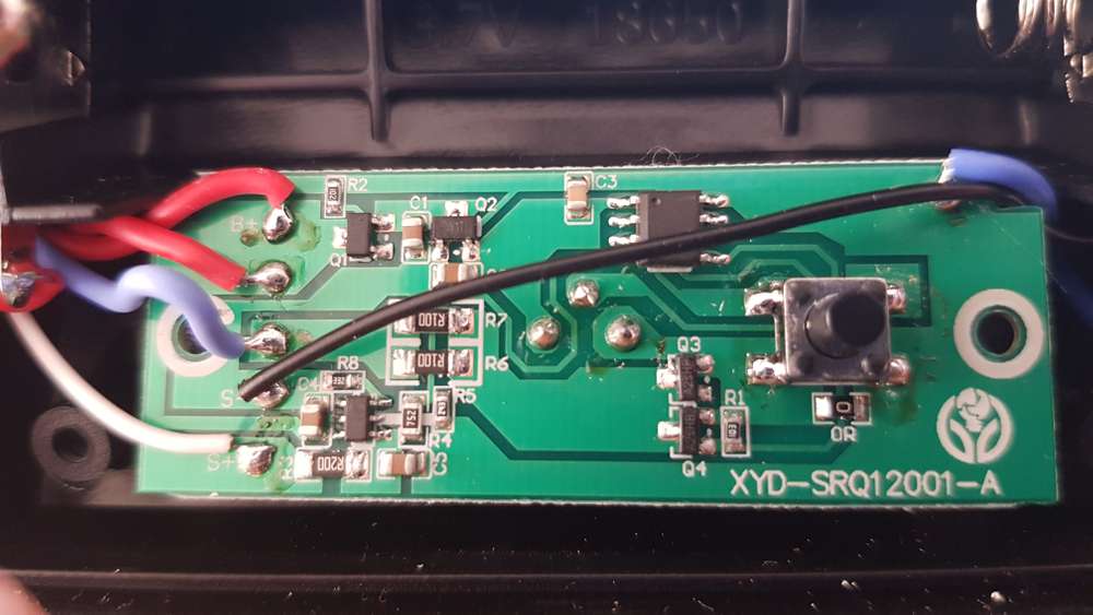
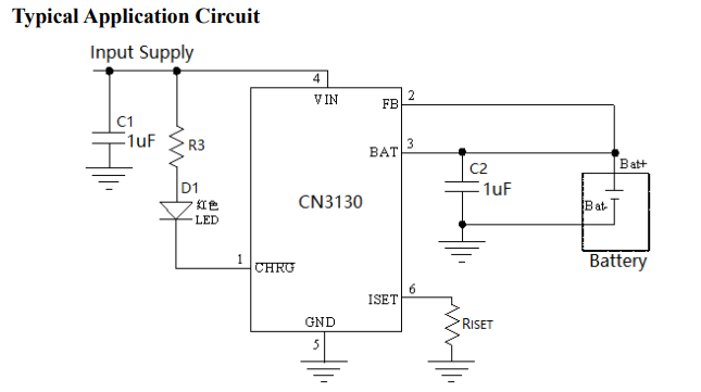
-Q1 / R2 = probably battery polarity and discharge protection - Solar charging IC (could be C3130) pins seems to match functionality:

- R8 (3K3) is probably RiSet
There is one 8 pin logic chip.
- Signal at Pin 2 is connected to the PIR
- Signal at Pin 3 is connected to voltage divider R4/R5 to detect sun light, (LEDS will switch off when there is sun light)
- Signal at Pin 4 is connected to the button (ON/OFF/Mode)
- Signal at Pin 5 to R1 is driving the leds via Q1/Q3 (N-channel Mosfet A2SHB) R7/R6 (2x 0.1) Ohm
- Q2 = voltage regulator 3.3 V To pin 1 of logic chip and PIR element
Hope to make some mysensor thing out of this soon.
Greetings A3
-
Is there a Gateway connection timeout?Hi all,
I build a gateway using an ESP32 and connected sensors directly to the gateway.
When the WIFI connection is not established at start up it hangs showing endlessly
GWT:TIN:CONNECTING
For sensor nodes using radio you can set MY_TRANSPORT_WAIT_READY_MS so it will timeout and do the sensor actions without radio connection.
Is there a Gateway connection timeout similar to MY_TRANSPORT_WAIT_READY_MS?
I want my Gateway/Sensor to continue setting-up and run when there is no WIFI and preferably retry,Any help is highly appreciated.
-
Nodemanager: How to control a local output from a local input?Reply to myself:
Looking thought the sources and the forum found out that you can do this using hooks.
so enabled hooking#define NODEMANAGER_HOOKING ONand added the reference to the hook to before.
void before() {
 Tsensor.setMeasureTimerMode(TIME_INTERVAL);   // set timer
 Tsensor.setMeasureTimerValue(1); // interval to 1 sec measurement

 Tsensor.setPostLoopHook(&myfirstHook);
 ..etc.etc...
 nodemanager.before();
}
And finally the hook
void myfirstHook(Sensor* sensor){
  float temperature =  Tsensor.children.get(1)->getValueFloat()
  Serial.println(temperature);
  if (temperature>setpoint) {
        if (Relay.getStatus()==OFF){
        Relay.setStatus(ON);      // switch off
        }


}
The error that I got initially was caused by using the wrong child: 0 (it starts from 1).
I wonder if it is possible to do interval < 1 second?
-
Nodemanager: How to control a local output from a local input?I am trying to make a temperature control system that has a temperature sensor and a relay.
I use an ESP32 and set it op as gateway. The sensor and relay are connected to the ESP32
The sensor and relay should form a closed loop and should be able to run independently from the (Domoticz) controller.
I want to use the Nodemanager to be able to track the temperature and relay state.
In my first test I can read my sensor and I can switch my relay from Domoticz.
I tried to add some code to the loop() to read the temperature locally and print it to the serial port:
When I e.g. try to print Tsensor.getChild(0)->getValueString() it throws an error.
My question: what is the proper way to do this?
How can I get the sensor value and set the relay?
Any suggestions are much appreciated -
Outdoor (neg temp) sensor for battery power projectYou can also use an analog temperature sensor like MCP9700.
Needs calibration and small calculations to get the results. There are libs available but you can do it in your code as well.
Is low power, low voltage, and can do negative.
I use it in an outdoor sensor on a similar slim node sending every 20 min. Running about 1 year now on 2 AA's. -
MYSBootloader 1.3 pre-release & MYSController 1.0.0beta@vidin You can simply program the 328pb with the standard bootloader using AVRDUDESS.
The pb version is software compatible with the p version.
